NASA will host an International Observe the Moon Night celebration from 5:30 to 8 p.m. CST on Saturday, Sept. 19, at the U.S. Space & Rocket Center, the official visitor center for NASA’s Marshall Space Flight Center in Huntsville, Alabama.
International Observe the Moon Night celebrates the Moon, the science behind it, and its connection to space exploration and human culture. NASA’s free public event will include agency experts delivering talks on lunar science and exploration and highlighting lunar observations made by the Artemis II crew in April.
Media interested in covering the event should confirm their attendance with Joel Wallace, joel.w.wallace@nasa.gov, in the NASA Marshall newsroom by 3 p.m., Friday, Sept. 18. Media must report to the Davidson Center to participate in the event. Visitor parking is available at the U.S. Space & Rocket Center.
NASA will have opportunities for media to capture visuals and interview agency experts. Activities available for coverage include hands-on STEM activities, a science stage show, an event photo booth, and face-painting.
The event also features Janet Ivey, the host of the television children’s series, “Janet’s Planet.” The Von Braun Astronomical Society will be on-site with telescopes, providing attendees with guided tours of the Moon, planets, and other celestial objects.
The evening is presented by the Planetary Missions Program Office at NASA Marshall.
For more information about International Observe the Moon Night, visit:
In April, the world watched as four humans circled the Moon for the first time in over 50 years with NASA’s Artemis II mission. On Saturday, Sept. 19, the public is invited to look up again with NASA events across the country, including the International Observe the Moon Night celebration held at NASA’s Goddard Space Flight Center Visitor Center in Greenbelt, Maryland.
This year, NASA will celebrate International Observe the Moon Night with people around the world on Sept. 19.
NASA/Vi Nguyen
International Observe the Moon Night is an annual celebration that brings people together to learn about the Moon and explore our connection to Earth’s nearest celestial neighbor. Since the program began in 2010, people around the world have participated through lunar observations, hands-on activities, artwork, music, and more.
At NASA Goddard, this year’s celebration will highlight the agency’s ongoing exploration of the Moon, including the historic Artemis II mission. Visitors can peer behind the scenes to learn more about what it took to make Artemis II’s journey around the Moon a success and discover how Goddard scientists and engineers are helping advance our understanding of the Moon, solar system, and beyond.
The event will run from 6 p.m. to 9 p.m. EDT.
Throughout the event at NASA Goddard, visitors can take part in interactive hands-on activities, create artwork and crafts, and capture selfies at a photo kiosk. Telescopes will also be set up outside (depending on weather), giving attendees an opportunity to observe the Moon and other astronomical objects up close. Inside the Visitor Center, guests can even see a real Apollo 14 Moon rock on display.
At 6:30 p.m., Dr. Amanda Nahm, planetary scientist at NASA Headquarters, will explore the lunar science and Moon joy from Artemis II.
At 7:30 p.m., Ernie Wright, scientific visualizer at NASA Goddard, will offer a more technical look at how scientists use real data to create videos and visualizations of the Moon.
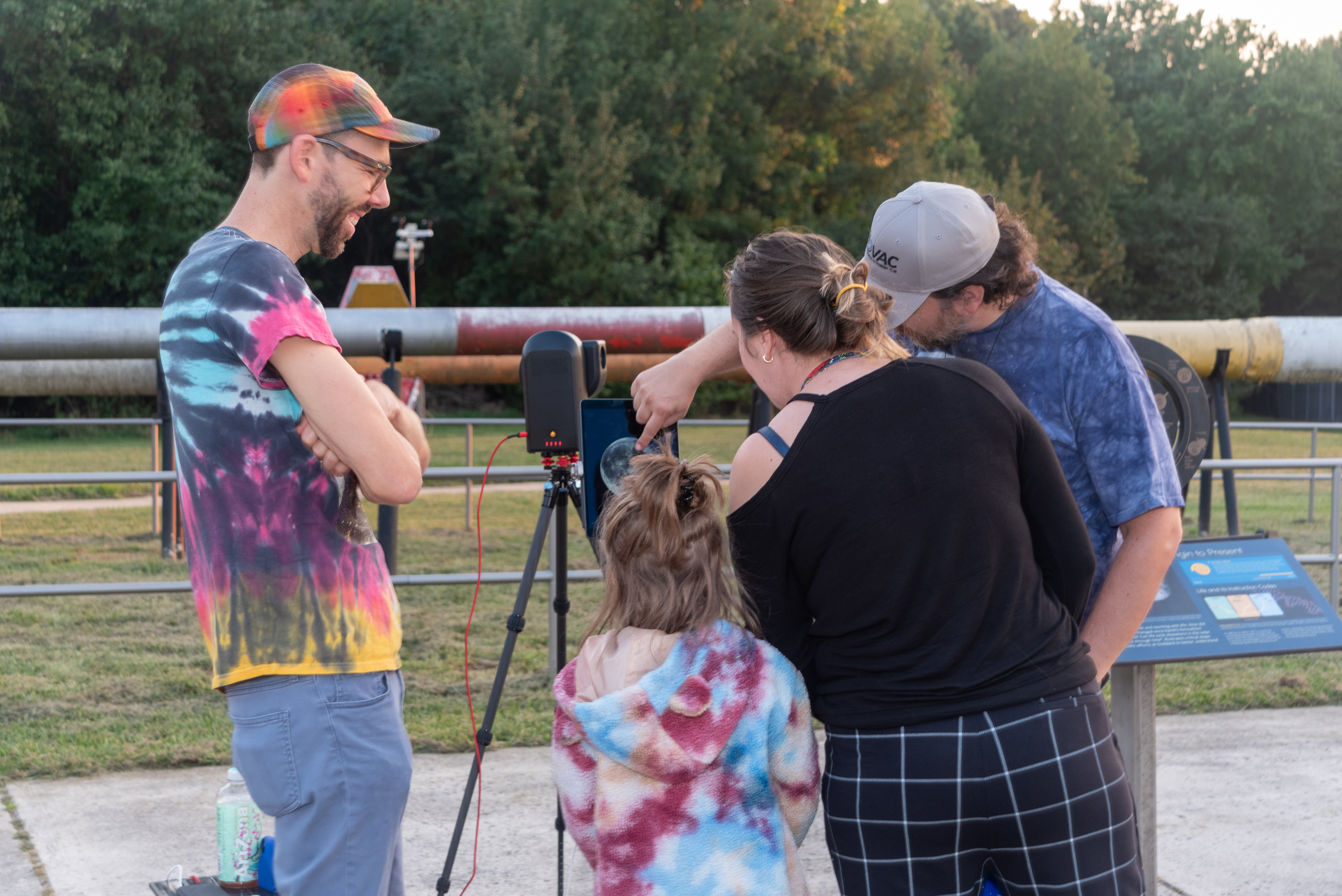
A family observes the Moon through a telescope at NASA’s Goddard Space Flight Center in Greenbelt, Md. during the International Observe the Moon Night celebration on Saturday, Sept. 14, 2024.
NASA/Britt Griswold
The event will also offer a chance to learn more about the groundbreaking research happening at NASA Goddard as scientists work to unlock the secrets of the Moon with missions like the Lunar Reconnaissance Orbiter (LRO) and explore our solar system and the universe beyond.
International Observe the Moon Night at Goddard is free and family friendly. Registration is not required, although registering in advance will help the Visitor Center team plan for the event. The event will take place rain or shine, and free parking is available at the Visitor Center.
For people who cannot travel to Greenbelt, there are opportunities to participate in International Observe the Moon Night from all around the planet. Join lunar observers around the world by observing the Moon with friends and family, attending a virtual event or finding an event in your area. Learn more and register your participation at go.nasa.gov/ObserveTheMoon.
International Observe the Moon Night is sponsored by NASA’s LRO mission and the Solar System Exploration Division of NASA’s Goddard Space Flight Center, with support from many partners. The celebration is a way for people to pause and look up at our future destination, as NASA prepares for deep space missions to the Moon and beyond.
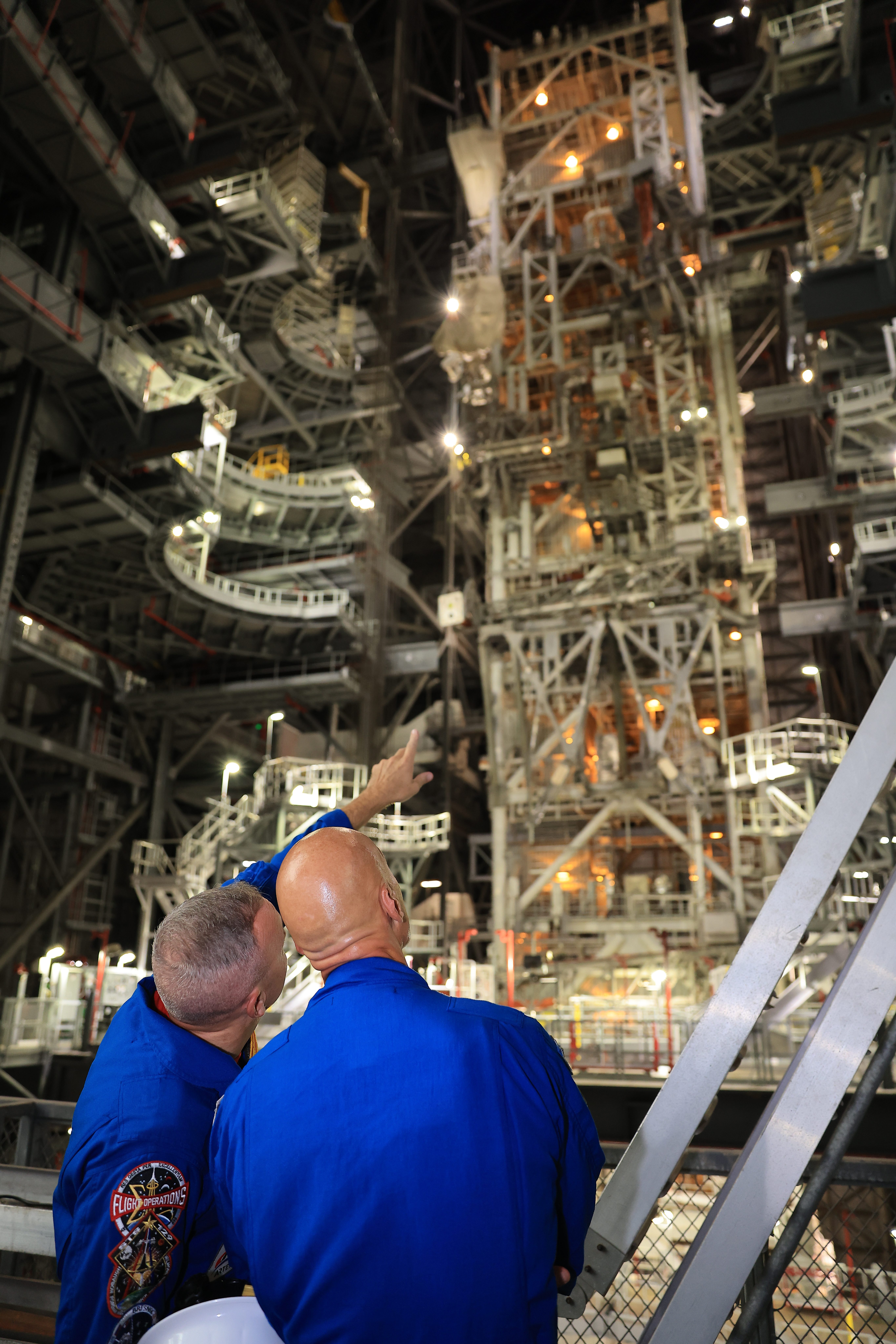
NASA astronaut Randy Bresnik (left) and ESA (European Space Agency) astronaut Luca Parmitano view progress on the solid rocket booster integration in High Bay 3 inside the Vehicle Assembly Building at NASA’s Kennedy Space Center in Florida on Wednesday, Sept. 2, 2026.
Bresnik, Parmitano, and NASA astronauts Andre Douglas, Frank Rubio, and Bob Hines made the first visit to Kennedy by the entire crew and backup crew members of the Artemis III mission. Artemis III will launch four crew members aboard the Orion spacecraft to carry out a series of objectives in low Earth orbit designed to demonstrate critical systems needed for future lunar landings, beginning with Artemis IV.
NASA’s Webb Reveals Dynamic Panorama of Star Formation
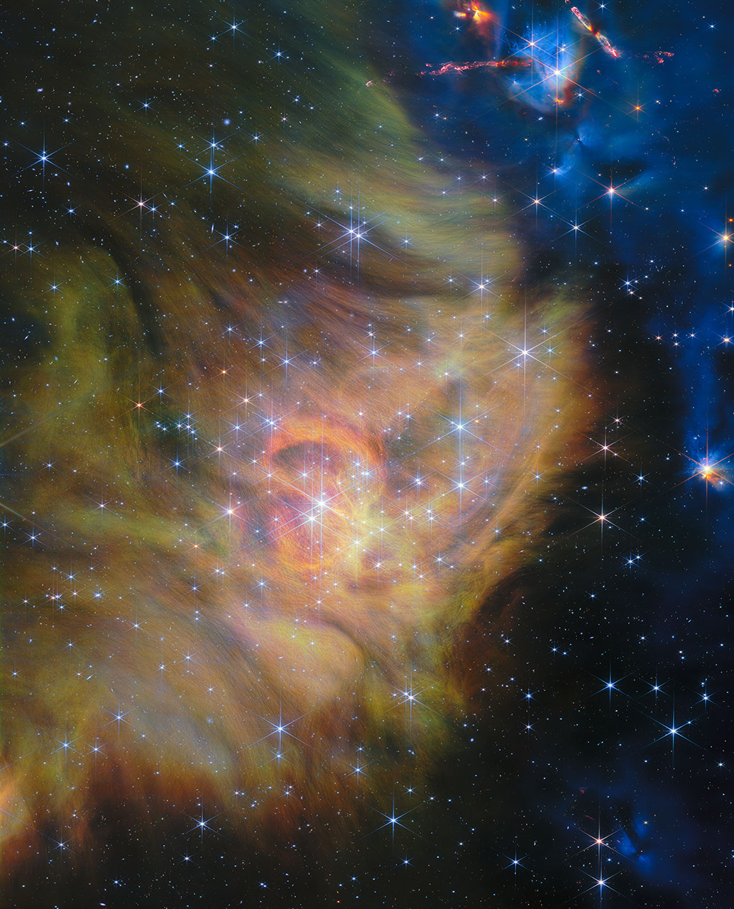
NASA’s James Webb Space Telescope recently observed IC 348, a star-forming region just 1,000 light-years away from Earth. Webb’s sharp vision revealed tiny brown dwarfs, some just twice Jupiter’s mass, and young stars ejecting powerful jets crashing into surrounding gas and dust.
Credits: Image: NASA, ESA, CSA, Kevin Luhman (PSU), Catarina Alves de Oliveira (ESA), Mahdi Zamani (ESA/Webb)
This starry view of the nearby star-forming region IC 348 is one of the largest images released to date from NASA’s James Webb Space Telescope. Using Webb, astronomers searched IC 348 for brown dwarfs, which are less massive than the smallest stars. The researchers discovered brown dwarfs just twice the mass of Jupiter, bringing the study of these curious objects into a new mass range and revealing new insights about the star formation process.
The star-forming region IC 348 is located just 1,000 light-years away in the constellation Perseus. In regions like IC 348, cold clouds of molecular hydrogen gas collapse to form new stars, creating glowing, sculpted scenes like this one. The star-formation process can create widely varied objects, from massive stars that expire after only a few million years in core-collapse supernova explosions to the smallest and most common stars, which are long lived and produce powerful stellar storms.
IC 348 (NIRCam Image)
NASA’s James Webb Space Telescope recently observed IC 348, a star-forming region just 1,000 light-years away from Earth. Webb’s sharp vision revealed tiny brown dwarfs, some just twice Jupiter’s mass, and young stars ejecting powerful jets crashing into surrounding gas and dust.
Image: NASA, ESA, CSA, Kevin Luhman (PSU), Catarina Alves de Oliveira (ESA), Mahdi Zamani (ESA/Webb)
The smallest stars weigh in at around 8 percent of the Sun’s mass. Below this mass lies a strange class of objects called brown dwarfs. Brown dwarfs form in the same way stars do, through the collapse of molecular clouds. However, unlike stars, the cores of brown dwarfs never become hot enough to fuse ordinary hydrogen into helium (though many briefly fuse deuterium, or heavy hydrogen, early in their lives).
What’s still not clear, and what researchers hoped to learn by using Webb’s sensitive instruments to study IC 348, is how small the smallest objects created by the star-formation process are. In other words, how small is the smallest brown dwarf?
The team used Webb’s NIRCam (Near-Infrared Camera) in 2024 to capture the warm glow of young brown dwarfs and newborn stars seen in this new image of IC 348. After selecting candidate brown dwarfs based on their colors and brightness, they followed up with Webb’s NIRSpec (Near-Infrared Spectrograph) in 2025 to conduct spectroscopic observations to study the masses of the brown dwarfs.
These deep Webb observations revealed something remarkable to the researchers: brown dwarfs with masses as low as just twice the mass of Jupiter or only 0.19 percent of the Sun’s mass — far smaller than theory predicts brown dwarfs should be. These are the least massive brown dwarfs known and their existence poses a challenge to models of how stars form.
In addition to the discovery of these unexpectedly lightweight brown dwarfs, the Webb observations contained even more surprises. One of the lightest newfound brown dwarfs showed signs of a disk, suggesting that small planets could be forming around an object that is itself only the mass of a planet.
While inspecting the spectra of IC 348’s brown dwarfs, the research team also found a feature they attributed to an unidentified hydrocarbon — molecules made only of hydrogen and carbon atoms. This specific feature has only been seen in the atmospheres of the lowest-mass brown dwarfs, suggesting that these extreme objects might exist in a spectral class of their own.
The stars and brown dwarfs of IC 348 aren’t the only attractions in this image. A brilliantly detailed collection of protostars occupies the upper right corner. Several of these protostars are accompanied by Herbig-Haro objects, which are luminous regions that form when jets from growing newborn stars crash into the gas and dust around the star.
The long, narrow feature that is oriented horizontally in this corner is the Herbig-Haro object HH 797. Upon close inspection, this source is revealed to be two protostars with nearly parallel outflows. Just to the right of HH 797 is the propeller-shaped source HH 211, which features both narrow jets and broader outflows.
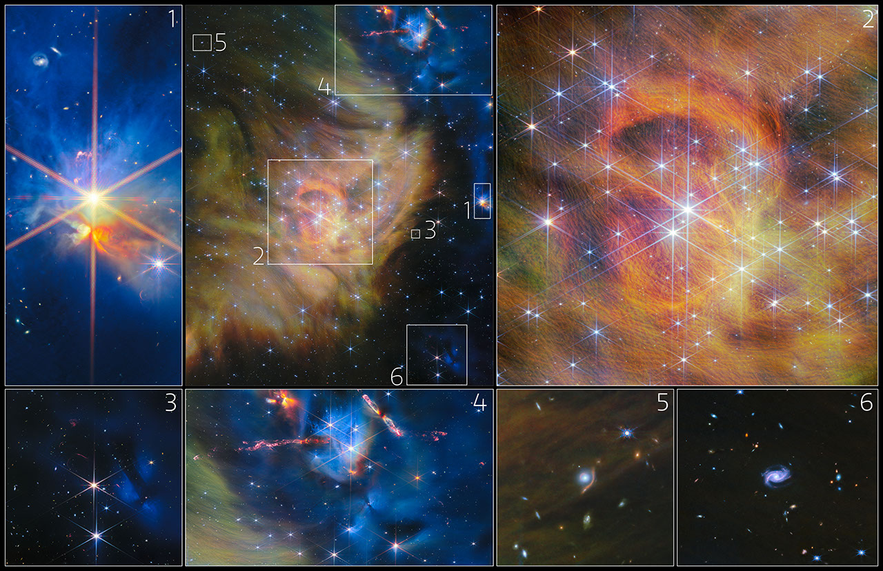
IC 348 Collage
This collage features a collection of insets from NASA’s James Webb Space Telescope’s image of star-forming region IC 348: embedded stars, a central star cluster, faint outflows, Herbig-Haro objects, gravitational lensing, and spiral galaxies.
Image: NASA, ESA, CSA, Kevin Luhman (PSU), Catarina Alves de Oliveira (ESA), Mahdi Zamani (ESA/Webb)
The data used to create this image comes from the Webb General Observer Program 4866. In addition to studying the lowest-mass objects created through the star-formation process, this program also seeks to understand how the populations of planetary-mass objects like brown dwarfs vary between star-forming regions, as well as the origins of the hydrocarbon feature in the lowest-mass brown dwarfs.
The James Webb Space Telescope is the world’s premier space science observatory. Webb is solving mysteries in our solar system, looking beyond to distant worlds around other stars, and probing the mysterious structures and origins of our universe and our place in it. Webb is an international program led by NASA with its partners, ESA (European Space Agency) and CSA (Canadian Space Agency).
The following sections contain links to download this article’s images and videos in all available resolutions followed by related information links, media contacts, and if available, research paper and Spanish translation links.
Related Images & Videos
IC 348 (NIRCam Image)
NASA’s James Webb Space Telescope recently observed IC 348, a star-forming region just 1,000 light-years away from Earth. Webb’s sharp vision revealed tiny brown dwarfs, some just twice Jupiter’s mass, and young stars ejecting powerful jets crashing into surrounding gas and dust.
IC 348 Collage
This collage features a collection of insets from NASA’s James Webb Space Telescope’s image of star-forming region IC 348: embedded stars, a central star cluster, faint outflows, Herbig-Haro objects, gravitational lensing, and spiral galaxies.
The NSSC provides travel reimbursement services for all authorized Agency travel including: domestic, foreign, local, ETDY, and Change of Station (COS).
POV Mileage for NASA Travelers
For Privately Owned Vehicle (POV) Mileage Reimbursement Rates for TDY and ETDY Travel please refer to the GSA Web site: http://www.gsa.gov/mileage
NASA Domestic Travel: Day that Travel Ends
For the day travel ends (the day a traveler returns to the PDS, home, or other authorized point), the per diem allowance is 75% of M&IE.
NASA Domestic Travel Rental Car Liability
When making a reservation for a rental car, please remember the Government is only responsible to pay for rental car charges for official travel time. If a traveler decides to take annual leave in conjunction with official travel and keeps the rental car during annual leave, the portion of the rental rate applicable to annual leave is the responsibility of the traveler. Please refer to 41 CFR 301-10.453
What is my liability for unauthorized use of a rental automobile obtained with Government funds?
You are responsible for any additional cost resulting from the unauthorized use of a commercial rental automobile for other than official travel-related purposes.
NASA Domestic Travel: Tax Exemption
Prior to traveling, refer to the GSA State Tax Information webpage: https://smartpay.gsa.gov/smarttax. Select your State/US territory of interest to see the exemption status and download the appropriate form, if required.
Extended Temporary Duty (ETDY)
Reduced Per Diem rate
NASA’s standard reduced per diem rate for ETDY travel is 65 percent under the current policy as defined in the NASA Procedural Requirements (NPR) 9750.1-3.1.2.
a. Consistent with 41 CFR 301-11.200, an ETDY authorization can include reasonable further reductions from this standard rate or limitations on approved lodging for unique circumstances, to the extent it can be determined in advance that such will substantially lower costs without mission impact. For example, if lodging is obtained at 50 percent per diem, the ETDY authorization should be adjusted to authorize a lower rate.
b. The reduced rate of reimbursement begins on the first day of travel regardless of the mode of transportation, except as noted in 3.1.3. Allowances are covered by the reduced per diem rate; therefore, NASA will authorize the employee a per diem rate (up to 65 percent) to reasonably cover expenses for a one bedroom furnished apartment. For ETDY greater than 90 days, first consideration should be given to long-term lodging facilities. Long-term lodging facilities are available on the GSA schedule at http://www.gsa.gov. If a long-term facility is not selected, proper justification should be provided.
Find more about Allowable ETDY Expenses Included in Reduced Per Diem Rate, please see the following document:
GSA’s Schedule 48 is designed for lodging needs of 30 days or more. This program provides housing accommodations for temporary or permanent relocation. Typical facilities include apartment or condominium type properties that may be furnished with all the amenities of a regular home. The current list of vendors is available by clicking on the link above. Most of these properties will accommodate NASA Extended TDY travelers within the 65% reduce per diem rate and will allow use of the government charge card.
Foreign Travel
Please consult the Code of Federal Regulations (CFR), NPR 9710.1, and NPR 9750.1. Please call the NSSC Contact Center using this form for additional information.
Preparations for Next Moonwalk Simulations Underway (and Underwater)
The members of NASA’s 2025 Astronaut Candidate Class pose with rock samples collected during their geology training at the Rio Grande del Norte National Monument, New Mexico, in May 2026.
NASA/Helen Arase Vargas
Did you spend part of your summer camping, hiking, at the pool, or in an aircraft? So did NASA’s 2025 Astronaut Candidate Class.
The 10 candidates have been working their way through a comprehensive and rigorous training program since the agency introduced them to the public on Sept. 22, 2025, from NASA’s Johnson Space Center in Houston. They are approximately halfway through the nearly two-year training program, which will equip them for missions to low Earth orbit, the Moon, and ultimately, Mars.
Geology Studies
Since the astronaut candidates can one day be assigned to a future Artemis mission to the lunar surface, geology courses are an important part of their training. In May, candidates completed classroom trainings at Johnson before venturing to the Rio Grande del Norte National Monument in New Mexico for additional classroom instruction and training in the field. Several candidates also joined NASA astronauts and Artemis mission support teams for geology field training in Iceland in July. They practiced geologic observations, sampling with tools, navigation, and teamwork, all skills and processes that translate directly to Artemis lunar missions.
NASA astronaut candidates study rock samples during a geology classroom training at NASA’s Johnson Space Center in Houston.
NASA/Helen Arase Vargas
NASA astronaut candidates Anna Menon, left, and Imelda Muller study a rock sample during a geology classroom training at NASA’s Johnson Space Center in Houston.
NASA astronaut candidates hiked through Rio Grande del Norte National Monument, New Mexico, during geology field training.
NASA/Helen Arase Vargas
JAXA (Japan Aerospace Exploration Agency) astronaut Akihiko Hoshide and NASA astronaut candidates Cameron Jones and Yuri Kubo participated in geology field training in Iceland, alongside NASA astronauts, Artemis mission support teams, and geology instructors.
NASA/James Blair
Flight Training
Whether learning to become a pilot or sharpening their existing piloting skills, astronaut candidates train in aircraft to build confidence, coordination, adaptability, and resilience in high-stakes environments. This summer, that training included flights on NASA’s WB-57s – a trio of long-range, high-altitude airplanes that have flown research missions since the 1960s. The class also began flying NASA’s T-38 supersonic jets.
NASA astronaut candidate Lauren Edgar prepares for flight training in one of NASA’s T-38 jets.
NASA astronaut candidate Rebecca Lawler, right, rides out to one of NASA’s WB-57 aircraft ahead of flight training at Ellington Field.
NASA/Josh Valcarcel
NASA astronaut candidate Adam Fuhrmann completes preflight checks of a WB-57 aircraft at Ellington Field.
NASA/Josh Valcarcel
NASA astronaut candidate Adam Furhmann sits inside the cockpit of a WB-57 aircraft as he prepares for flight training.
NASA/Josh Valcarcel
Altitude Chamber Runs
Candidates have also spent time in one of Johnson’s altitude chambers as part of their flight training. These unique facilities allow NASA to simulate physical pressure levels ranging from those at sea level to near vacuum. After donning flight suits and helmets, candidates enter the chamber to familiarize themselves with the conditions they will face on high-altitude flights and in space, and to practice different protocols and interventions designed to keep them safe.
April 8, 2025
NASA astronaut candidates Adam Fuhrmann and Rebecca Lawler prepare to conduct altitude chamber runs as part of their flight training.
NASA astronaut candidate Adam Fuhrmann sits inside the altitude chamber at NASA’s Sonny Carter Training Facility in Houston.
NASA/James Blair
A NASA team member observes astronaut candidate Adam Fuhrmann as he completes an altitude chamber run.
NASA/James Blair
Water Survival Training
Candidates continued survival training to prepare for the unlikely event of landing in remote environments after a mission. Water survival exercises in Johnson’s Neutral Buoyancy Laboratory, or NBL, simulate these scenarios while also building teamwork and decision-making skills.
Some components of astronaut candidates’ water survival training are completed during simulated storms inside of the Neutral Buoyancy Laboratory.
NASA/Morgan Gridley
A NASA astronaut candidate practices being lifted out of the water during survival training in the Neutral Buoyancy Laboratory.
NASA/Robert Markowitz
NASA astronaut candidate Rebecca Lawler floats in a raft during water survival training at the Neutral Buoyancy Laboratory.
NASA/Robert Markowitz
On top of these exercises, candidates are completing intensive Russian language classes and cross-cultural training to prepare for missions spanning countries and continents. They are learning to operate spacecraft systems used in human spaceflight missions, conducting spacewalk training at the NBL, and training inside other mockups of space vehicles. They are also learning emergency procedures, maintenance, and repair of spacecraft.
The class is on track to graduate in 2027, when they will join NASA’s active astronaut corps and await their first flight assignments. Whether they go on to contribute to research taking place aboard the International Space Station or venture to the Moon to prepare for future Mars missions, the graduates will have the operational expertise, scientific knowledge, and technical background necessary to advance NASA’s deep space exploration goals and sustain a long-term human presence beyond low Earth orbit.
Autumn color sweeps across the low-growing shrubs and tundra vegetation of Nunavut, Canada, in this image pair captured by the OLI (Operational Land Imager) on Landsat 9. NASA Earth Observatory images by Michala Garrison.
As North America rode out a summer of remarkable heat, fall foliage and cool, crisp weather still seemed like distant, alien concepts across much of the continent in early September 2026. But fall comes early in the tundra and subarctic ecosystems of Nunavut, in far northern Canada.
Vivid signs of the season were already sweeping across the landscape on September 6 when the OLI (Operational Land Imager) on Landsat 9 captured this image (right) of the Coppermine River winding through low-growing shrubs and tundra vegetation upriver of Kugluktuk, a community at the river’s mouth. The other image (left) shows the same area on July 27, 2026, when vegetation was still green.
The region is known for willow and birch shrubs, blueberries, bearberries, and other low-growing tundra plants that turn shades of red, orange, and yellow each fall. A NASA and South Dakota State University analysis of seven years of satellite data found that foliage in the region begins to change in early September and peaks in mid-month, making this one of the first places on the North American continent to change color. But blink and you might miss it: the analysis also showed that far northerly regions tend to have shorter periods of peak color—sometimes a week or less—compared to many lower-latitude areas.
In the fall, leaves change colors as they lose chlorophyll, the molecule that plants use to synthesize food. Chlorophyll makes plants appear green because it absorbs the red and blue light from sunlight as it strikes leaf surfaces. However, chlorophyll is not a stable compound, and plants must continuously synthesize it, a process that requires ample sunlight and warm temperatures. As temperatures drop and days shorten in autumn, levels of chlorophyll fall as well.
As concentrations of chlorophyll decline, the green fades from leaves, presenting an opportunity for other pigments—carotenoids and anthocyanins—to take the stage. Carotenoids absorb blue-green and blue light, so in the absence of chlorophyll, they cause leaves to appear yellow. Anthocyanins absorb blue, blue-green, and green light, so light reflecting off the pigments appears red.
Citizen scientists have an opportunity to help NASA scientists track fall color and contribute to long-term environmental databases with the GLOBE North American Phenology Campaign. Participants observe and record leaf color changes during the spring and fall, helping scientists understand plant responses to climate and environmental changes.
NASA Earth Observatory images by Michala Garrison, using Landsat data from the U.S. Geological Survey.Story by Adam Voiland.
NASA’s Life-Saving Technology Where Cell Signals Can’t Go
Rescued after more than four hours in the water, Easton Barrett (center, red shorts) and his friend were picked up by the U.S. Coast Guard thanks to a personal locator beacon (PLB). The devise sends a distress signal to satellites that are relayed back to Earth, launching a rescue operation.
Credits: Easton Barrett
Memorial Day weekend 2024 started with a blue sky and a mild three- to four-foot chop in the water off the Gulf Coast of Mississippi — a perfect day for a fishing competition. A team of five was about 40 miles offshore checking their sonar, and 30 seconds later the boat was gone. They were in the water struggling to pull on life jackets and grab the coolers as they bobbed up. When a boat sinks, survivors can be virtually invisible amid the vast expanse of water.
When their fishing trip went wrong, Easton Barrett had the only mobile phone and no cell service. He recorded a brief farewell, planning to put his phone in a cooler in hopes someone would find it.
Another team member activated a personal locator beacon (PLB) that had been stowed at the last minute, which sent a distress signal to the Search and Rescue Satellite-Aided Tracking (SARSAT) technology carried by multiple satellites in Earth orbit. In the SARSAT system, developed partly by NASA, an emergency signal containing the transmitter’s location is directed to the nearest available ground station.
406 megahertz is the wavelength dedicated for PLB distress signals. On the annual 406 Day, Easton Barrett posts videos and messages on his social media accounts to help raise awareness about essential survival gear.
Credit: ACR
A mission control center then alerts rescue coordination centers to mobilize search and rescue crews. For Barrett and his crew, that was a Florida Coast Guard boat.
“Ever since, I have tried to teach others about safety on the water and in the outdoors by using a PLB,” said Barrett. “If that will save one life, it’s worth the effort.”
A beacon like the one that saved his crew, a registered ResQLink PLB developed by ACR Electronics Inc. of Fort Lauderdale, Florida, also notifies the device owner’s emergency contact, indicating a distress call was activated. All emergency beacons must meet the same requirements to ensure they work when needed. Every rugged, buoyant, handheld devices have a five- to 10-year battery life.
SARSAT began operations in 1982, becoming an international collaboration in 1985. The flight and ground technologies used globally were originally developed at NASA’s Goddard Space Flight Center in Greenbelt, Maryland. Now there are 62 satellites in the program and 45 nations contributing services, from operating ground stations to providing rescue crews. More than 63,000 lives have been saved.
Turning on a ResQLink View PLB from ACR Electronics will automatically “ping” orbiting satellites that send location and GPS information
to the nearest search and rescue station. Whether on land or water, the appropriate resources will be dispatched to help anyone in distress
anywhere in the world.
Credit: ACR
SARSAT by the Numbers
The Search and Rescue Satellite-Aided Tracking system developed over several decades by NASA and other government agencies saves lives on land or at sea.
1982 — the start of U.S. operations
1985 — the start of international operations
62 operational satellites
45 nations contributing services
63,000+ lives saved
One rescue in 2024 demonstrates how it all comes together.
40 miles off the Mississippi Gulf Coast
5-person team participating in a fishing competition
30 seconds for a boat to sink
200 pounds of bait dumped to make a cooler buoyant
3 close encounters with wildlife, likely sharks and eels
4 hours in the water
1 personal locator beacon
1 Coast Guard rescue boat
5 lives saved
“If it has anything to do with NASA, it's got to be awesome.”
A NASA Launch Services (NLS) II contract has been awarded by the agency to Relativity Space Inc., and its Terran R launch service in accordance with the contract’s on-ramp provision. The Terran R launch service will be available to NASA’s launch services to use for future missions.
The NLS II contracts are multiple-award, indefinite-delivery/indefinite-quantity contracts with an ordering period through June 2030 and an overall period of performance through December 2032. The NLS II contracts include an on-ramp provision that provides an opportunity annually for new launch service providers to compete for future missions and allows existing contractors to introduce launch vehicles not currently on their NLS II contracts.
The NLS II contracts support the goals and objectives of the agency’s Human Spaceflight Mission Directorate, Science Mission Directorate, and the Research and Technology Mission Directorate. Under the contract, NASA also can provide launch services to other government agencies, such as the National Oceanic and Atmospheric Administration.
NASA’s Launch Services Program Office at the agency’s Kennedy Space Center in Florida manages the NLS II contracts. For more information about NASA, visit:
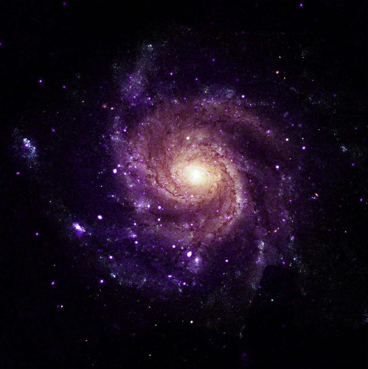
X-ray: NASA/CXC/Univ. of Alabama/M. Muhibullah et al.; Optical: NASA/ESA/STScI; Image Processing: NASA/CXC/SAO/N. Wolk
Using NASA’s Chandra X-ray Observatory, scientists have discovered a new class of objects behaving unlike any they have seen before. Astronomers suggest these newly spotted objects in other galaxies may help solve not one, but two long-standing questions in astrophysics.
These mysterious objects give off unusually low-energy X-rays but intense levels of ultraviolet radiation. This discovery is featured in a paper published Wednesday in Nature Astronomy.
“We’ve never encountered a group of objects that act like this,” said Mustafa Muhibullah of the University of Alabama who led the study. “Of course, the next step was to try to figure out what these things are.”
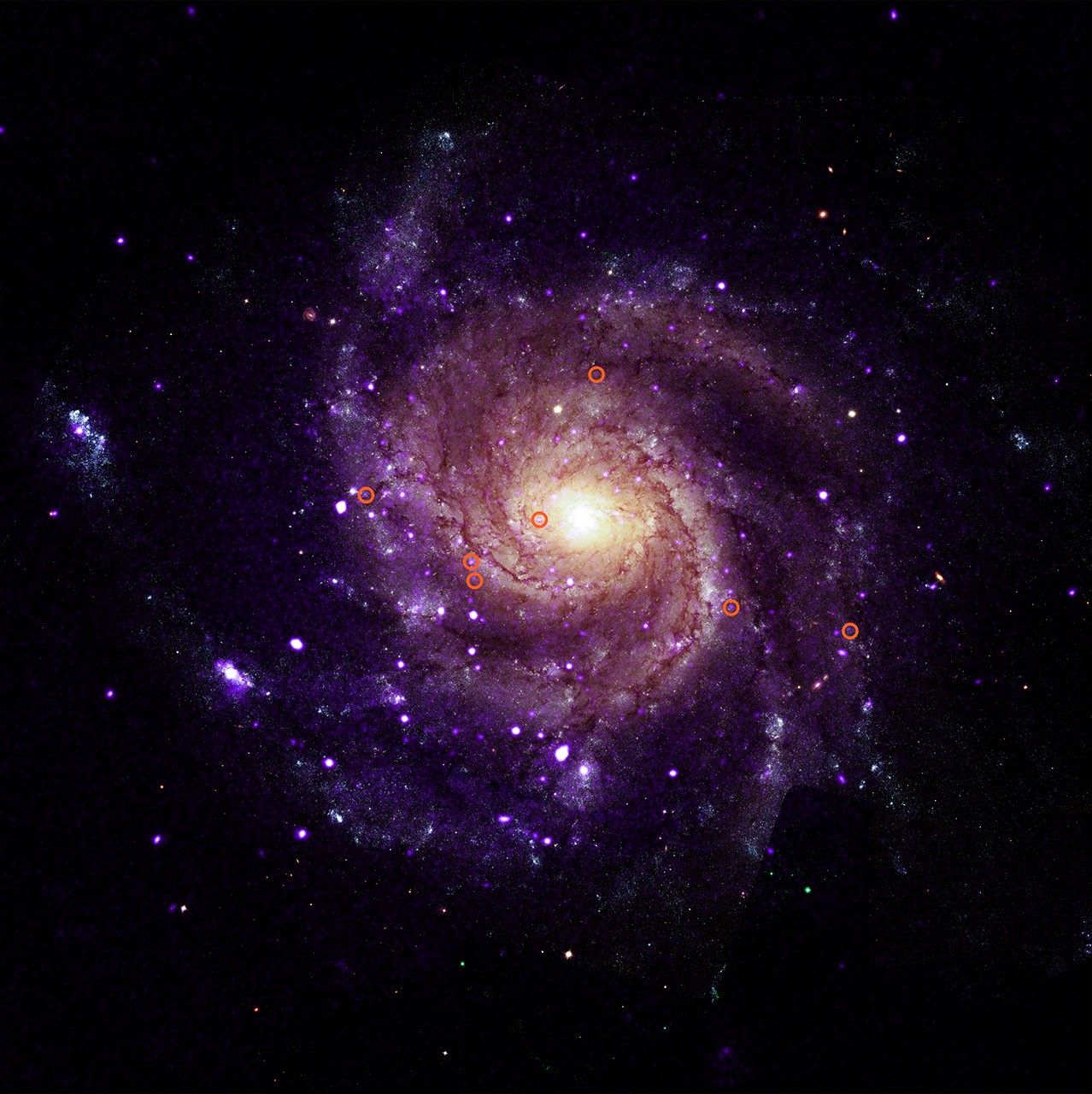
M101 with illustrated circles calling out seven of the newly-discovered objects.
X-ray: NASA/CXC/Univ. of Alabama/M. Muhibullah et al.; Optical: NASA/ESA/STScI; Image Processing: NASA/CXC/SAO/N. Wolk
The researchers found a total of 84 of these “hypersoft X-ray sources” – so named because they give such low-energy X-rays – in the six different galaxies they searched, using data openly available to the public in the Chandra archive. Two of the galaxies are spirals, M31 (the Andromeda galaxy) and M101 (the Pinwheel galaxy), while the other four are ellipticals. They found hypersoft X-ray sources both in regions of active star formation and areas where there are older stars.
The team spotted the sources by finding objects that appeared in Chandra images taken at the lowest X-ray energies but vanished in higher-energy images. That means these objects give off far more low-energy X-rays than high-energy ones. Because low-energy X-rays border energetic ultraviolet radiation on the electromagnetic spectrum, the researchers determined that these sources are producing large amounts of energetic ultraviolet radiation as well.
It is unclear what types of objects are responsible for these low-energy X-rays and intense ultraviolet radiation. The team thinks they most likely involve a black hole, neutron star, or white dwarf pulling material from a companion star. The material pulled from the companion star is heated up to produce X-rays before falling onto the white dwarf or neutron star, or into the black hole. Such binary systems have been seen before, but not with such bright ultraviolet radiation and low-energy X-rays.
The discovery suggests that there may be large populations of binary systems with energetic ultraviolet radiation that have been undetected until now.
“These clandestine X-ray sources are actually among the most energetic objects in galaxies, and they could be solving two cosmic mysteries at once,” said Muhibullah.
Scientists think that some white dwarf systems pulling material from companion stars may eventually explode as a supernova – known as a Type Ia – that is critical for measuring the expansion of the universe. These supernovae played a key role in discovering that this expansion is accelerating. Astronomers have been looking for the stars that turn into Type Ia supernovae for many years, so far without success.
“If we could find a way to spot these Type Ia supernova explosions before they go off, that would be really important,” said co-author Jimmy Irwin, also of the University of Alabama. “Right now, we study them after they’ve exploded, and astronomers have struggled to understand what is actually ignited.”
The other mystery these hypersoft X-ray sources might explain is what strips electrons from gas between the stars in some galaxies. This stripping of electrons is important to probe because it can affect how quickly stars form and influence the life cycles of galaxies. Hot, massive stars play a role, but they do not completely explain what is causing this stripping. The intense levels of ultraviolet radiation from the hypersoft X-ray sources may play a vital role.
Why were these hypersoft X-ray sources not found until now? In addition to the low-energy X-ray output, which is very difficult for X-ray telescopes to detect, the high-energy ultraviolet radiation is readily absorbed by helium and hydrogen gas that fills the space between the stars, creating a nearly impenetrable barrier to look through.
“By combing through the Chandra archive, we were able to eliminate what used to be a blind spot for telescopes,” said co-author Rosanne Di Stefano of the Center for Astrophysics | Harvard & Smithsonian. “That’s how we found what appears to be a new class of cosmic objects with remarkable qualities.”
NASA’s Marshall Space Flight Center in Huntsville, Alabama, manages the Chandra program. The Smithsonian Astrophysical Observatory’s Chandra X-ray Center controls science operations from Cambridge, Massachusetts, and flight operations from Burlington, Massachusetts.
This release features a composite image of a spiral galaxy, M101; one of six identified galaxies housing a new class of mysterious objects that give off unusually low-energy X-rays.
In this composite image, M101 faces us directly. It has multiple arms in shades of purple, spiraling clockwise around a golden yellow core. Scattered along and between the arms are scores of tiny specks in white and purple. Most of those specks are pairs of stars, but seven of them are a mystery.
To casual observers, the unusual objects are visually indistinguishable from the other specks of light in the galaxy. An annotated version of the composite image is included in this release, with red circles around the mysterious specks for easy identification.
These mystery specks behave like no other class of object discovered before. The curious objects give off X-rays of such low energy, they in fact produce large amounts of ultraviolet radiation, as UV radiation borders X-rays on the electromagnetic spectrum. Searching images of galaxies with low-energy X-rays in the Chandra Observatory archive, scientists have found a total of 84 such objects spread across M101 and five other galaxies. They have dubbed these mysterious objects “hypersoft X-ray sources.”
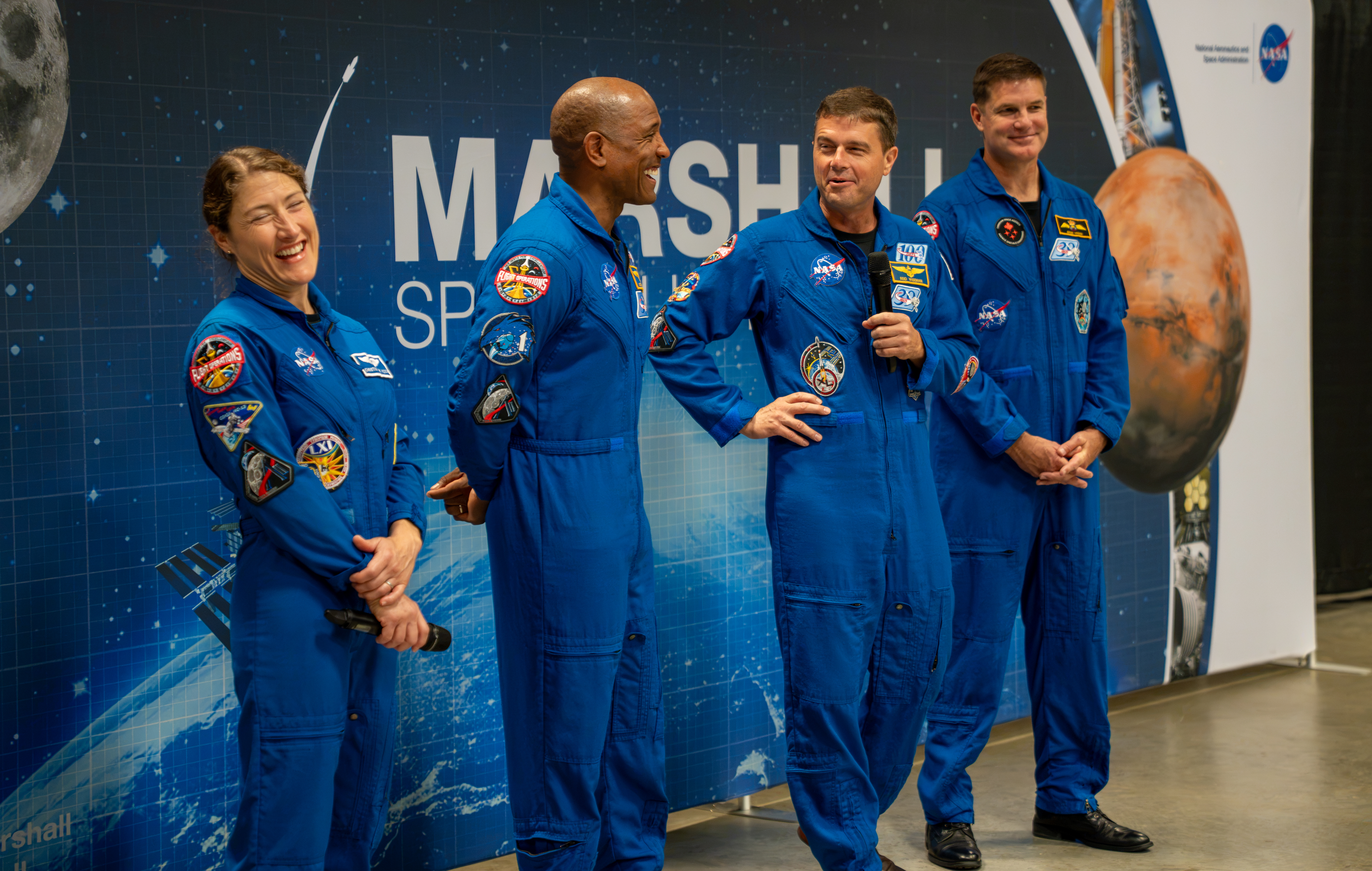
The crew of NASA’s Artemis II mission – NASA astronauts Christina Koch, Victor Glover, and Reid Wiseman and CSA (Canadian Space Agency) astronaut Jeremy Hansen – visited Huntsville, Alabama, Sept. 1, 2026, where they met with the NASA workforce at NASA’s Marshall Space Flight Center. The event gave the crew an opportunity to share firsthand experiences from their mission, reflect on their time in space, and connect with the workforce that supported the mission through an engaging question-and-answer session.
Preparations for Next Moonwalk Simulations Underway (and Underwater)
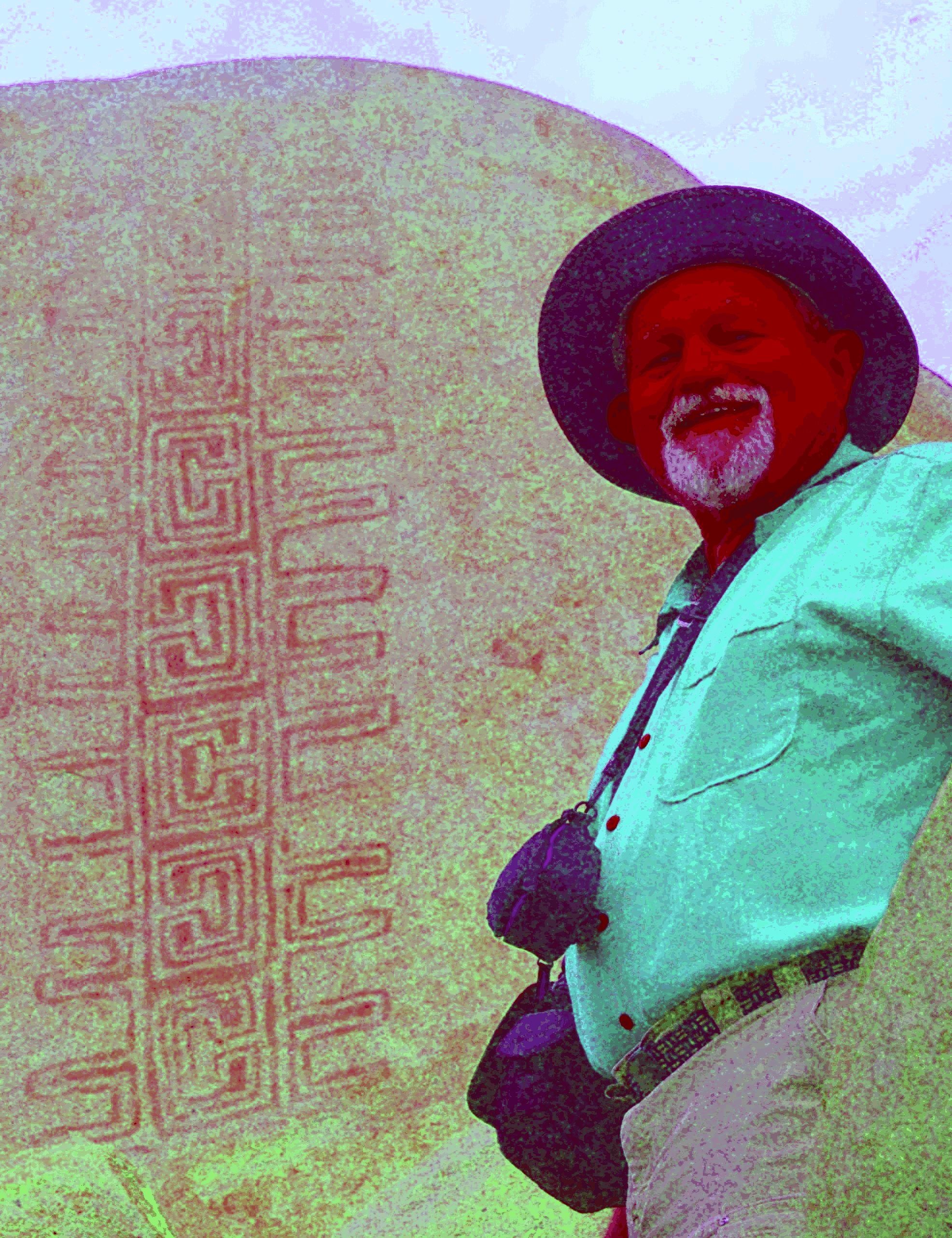
Jon Harman poses in front of an example of the Rancho Bernardo style of Native American artwork that’s barely visible until Dstretch is applied.
Credit: Jon Harman
High in the central tower in the ancient Cambodian temple of Angkor Wat, paintings depict horseback riders and a traditional musical ensemble. Thousands of visitors pass these images daily without noticing, because they’re faded to the point of invisibility.
They were discovered between 2010 and 2012, along with about 200 other paintings throughout the complex, by an archaeologist using a method conceived at NASA’s Jet Propulsion Laboratory in Southern California.
The technique, known as decorrelation stretch, heightens contrasts in digital imagery, making features easier to spot. It is especially popular for studying ancient rock art, partly due to the chance intersection of one man’s hobby with his professional background.
Around 2005, rock art enthusiast Jon Harman saw NASA images depicting the Martian surface with and without the application of decorrelation stretch. Seeing how much detail the technique revealed, Harman, now retired in Pacifica, California, understood the implication for studying ancient, faded images.
He also worked in medical imaging. “I Googled it and found a NASA paper that explained how to do the algorithm,” he said. “I knew from my medical imaging experience that I could do it, so I did.”
The paper was written in 1996 by Ronald Alley, a JPL employee developing applications for the Advanced Spaceborne Thermal Emission and Reflection Radiometer (ASTER), a Japanese imaging instrument on NASA’s Terra satellite. One of Alley’s former supervisors at JPL had coinvented decorrelation stretch, and Alley had recognized its potential for gleaning information from ASTER imagery.
Harman made his plug-in for use with ImageJ, an open-source program developed by the National Institutes of Health.
before
after
before
after
Before and After
Dstretch applied to Cave of San Borjitas in Baja California, Mexico
As Jon Harman was developing the Dstretch plug-in, he applied it to this image from the Cave of San Borjitas in Baja California, Mexico. When the yellow figure appeared in the middle of the picture, he knew he had something useful. Credit: Jon Harman
He said he fulfills about 200 requests for Dstretch per year. Around 2010, he also created smartphone apps that use a shortcut to mimic decorrelation stretch. The apps have been downloaded thousands of times, and papers have been published describing Dstretch’s usefulness in archaeology.
It has been used to spot and clarify imagery at ancient sites under a cliff in Norway, in an Egyptian tomb, at a park in Canada, and in many other locations. It has also helped archaeologists find buried remains of ancient Greek buildings and examine tattoos on mummified human remains, among its non-rock-art applications.
Harman said he was not surprised Dstretch found wide use in the rock art community. “But I’ve been surprised by a lot of the different applications people have found. So that’s been cool.”
NASA’s Hubble, Webb Find Far-out Solar System Objects ‘Remember’ Past
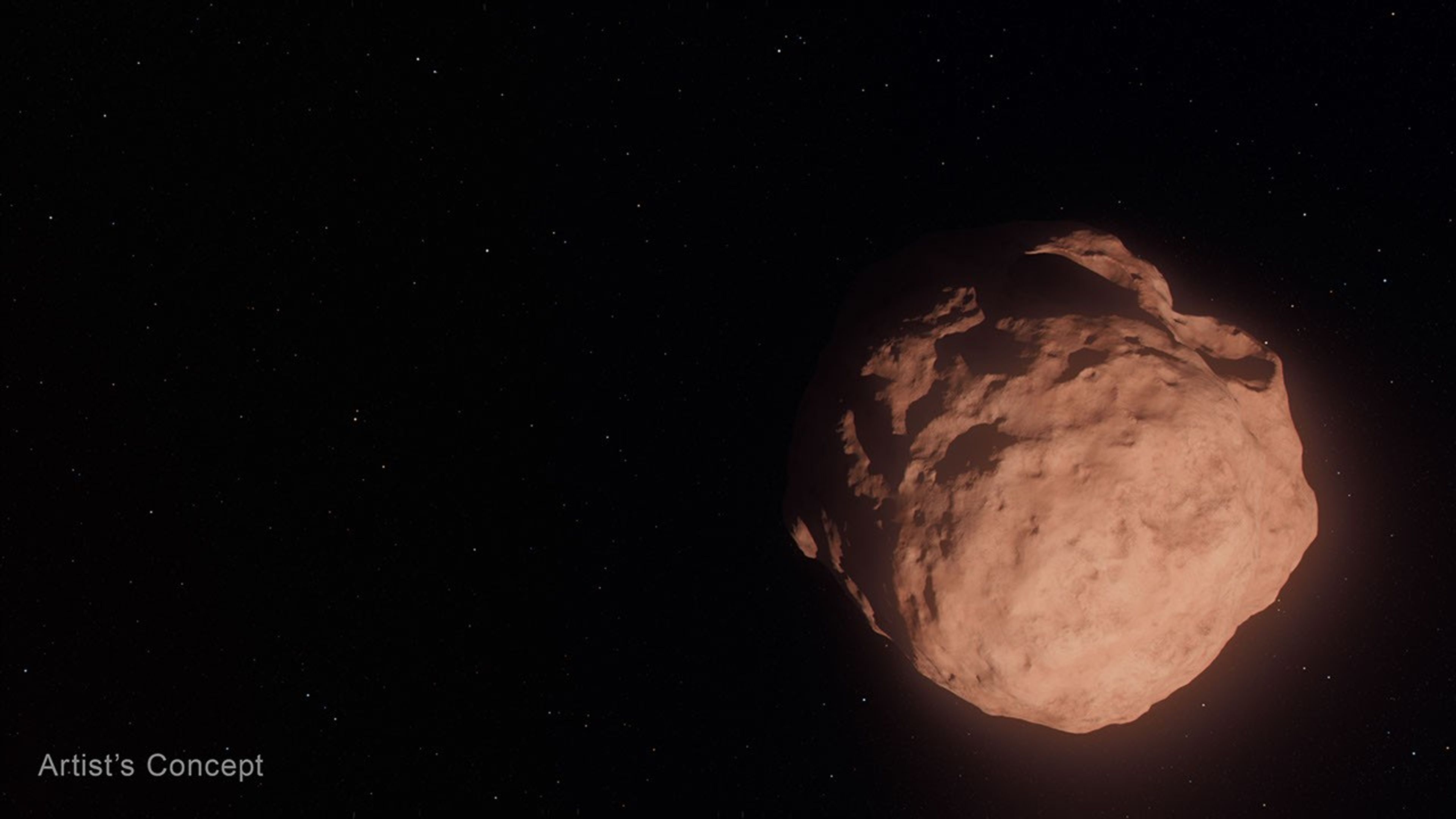
This artist’s concept depicts a Trans-Neptunian Object, a small, faint, icy body orbiting the Sun beyond the orbit of Neptune. These objects are so small that even with NASA’s Hubble and Webb space telescopes, they appear only as tiny points of light.
Artwork: NASA, ESA, Leah Hustak (STScI)
For the first time, scientists used the joint power of NASA’s Hubble and James Webb Space Telescopes to study some of the most far-flung bodies in our solar system, Trans-Neptunian Objects (TNOs). Some of these are the smallest and faintest ever directly seen. The researchers unexpectedly found fewer small TNOs than they expected, and that the colors of these bodies followed the same relationships as their larger family members.
These objects are typically small, faint, icy bodies orbiting the Sun beyond the orbit of Neptune. Most are more than 100 million times dimmer than objects visible to the unaided eye. In two complementary papers published Tuesday in The Astronomical Journal, teams analyzed the color, composition, and size distribution of 27 newly discovered tiny, dim TNOs.
This class of small bodies offers the best view into an early stage of planet-building, when a disk of dust and pebbles in orbit around the Sun coalesced into city-sized “planetesimals” — the solid building blocks that clump together to form planets — but had not yet merged into full-sized worlds. Beyond Neptune, this second stage never happened, leaving behind a frozen population of planetesimals.
In the deepest TNO survey to date, teams led by PhD candidates from the University of Victoria in Canada, under the guidance of the National Research Council of Canada, and Northern Arizona University in Flagstaff examined a patch of sky simultaneously with Hubble, observing the TNOs’ visible light, and Webb, observing their infrared light. The team of researchers measured the objects’ colors, which are like a fingerprint of the surface composition, as well as their sizes and determined their orbits.
In the coordinated observations, the teams studied two different types of TNOs. The first, dynamically “cold” TNOs, are on their original, relatively circular orbits around the Sun in the plane of the solar system. The second type, dynamically “hot” TNOs, formed between the current locations of Uranus and Neptune but were pushed outward where they are today when the outer gas giants migrated early in the solar system’s history. Today they reside in highly elliptical orbits and move in and out of the plane of our solar system.
NASA’s Goddard Space Flight Center; Lead Producer: Paul Morris
Prior to these observations, astronomers thought that small TNOs from both hot and cold populations would have undergone many collisions, changing their surfaces compared to larger TNOs. But that’s not what the observations showed. Instead, the small bodies look like their larger counterparts. This implies that collisions are not changing the surfaces significantly—perhaps because there are fewer collisions than expected, or because the TNOs somehow retain their primordial, pre-collision compositions. The teams are still trying to unravel this mystery.
“You could imagine a scenario where getting knocked around and fragmented would change the surface composition, and then you would see a different surface color for tiny TNOs compared to their larger siblings. So it’s really fascinating to see that the smallest objects are somehow ‘remembering’ and preserving the history of how they were made,” said Northern Arizona University PhD candidate Anastasia Morgan, who led the study of color and composition.
“These dynamically ‘hot’ TNOs retain a signature of where they were born, even though they’ve been orbitally scrambled since then,” said co-author David Trilling of Northern Arizona University.
Both the “hot” and “cold” populations seem to keep the same colors as when they were formed, with little change since the birth of the solar system.
The Webb data also allowed researchers to measure the number of objects of each size. They found that the overall size distributions for both populations were surprisingly similar.
“It’s very interesting that the process of planetesimal formation ends up producing the same distribution of sizes for both cold and hot populations, despite forming in different regions of the early solar system. The process seems to be insensitive to disk conditions, producing similar planetesimal sizes whether the disk is hot or cold, and dense or fluffy,” said University of Victoria PhD candidate Marielle Eduardo, who led the study on size distribution.
Researchers also found fewer of these very small bodies than they expected based on some planet formation models. Webb discovered 27 new, remarkably dim TNOs, one so faint it is equivalent to standing on Earth and seeing a small swarm of fireflies on the Moon. The smallest one they observed has a diameter of about 3 miles (5 kilometers), which is about five times smaller than what is possible to detect with the most sensitive ground-based telescopes.
This project would not have been possible without Hubble and Webb working together to detect and characterize these TNOs. With Hubble’s sensitivity in visible light and Webb’s in infrared, the space telescopes provide more insights than either can on its own.
The Hubble Space Telescope has been operating for over three decades and continues to make ground-breaking discoveries that shape our fundamental understanding of the universe. Hubble is a project of international cooperation between NASA and ESA (European Space Agency). NASA’s Goddard Space Flight Center in Greenbelt, Maryland, manages the telescope and mission operations. Lockheed Martin Space, based in Denver, also supports mission operations at Goddard. The Space Telescope Science Institute in Baltimore, which is operated by the Association of Universities for Research in Astronomy, conducts Hubble science operations for NASA.
The James Webb Space Telescope is the world’s premier space science observatory. Webb is solving mysteries in our solar system, looking beyond to distant worlds around other stars, and probing the mysterious structures and origins of our universe and our place in it. Webb is an international program led by NASA with its partners, ESA (European Space Agency) and CSA (Canadian Space Agency).
This artist’s concept depicts a Trans-Neptunian Object, a small, faint, icy body orbiting the Sun beyond the orbit of Neptune. These objects are so small that even with NASA’s Hubble and Webb space telescopes, they appear only as tiny points of light.
Tiny Worlds Discovered by Hubble and Webb
This video explains how Hubble and Webb are giving scientists a new look at some of the solar system’s oldest survivors and revealing new clues about how the building blocks of planets, including Earth, first formed.
Explore More
NASA’s Hubble Finds Kuiper Belt Duo May Be Trio
A team of researchers found a potential three-body system in the Kuiper Belt. The system, known as the Altjira, challenges traditional collision theories by suggesting that these triple systems might form directly from the gravitational collapse of material in the early solar disk.
NASA’s Webb Reveals the Ancient Surfaces of Trans-Neptunian Objects
Within the first two years of science operations, Webb took high-quality spectra of over 75 TNOs and provided the first comprehensive look at what they are made of.
Uncovering Icy Objects in the Kuiper Belt
Hubble observations of the outskirts of our solar system found a moon orbiting Makemake and several new moons around Pluto. These observations played a critical role in helping NASA plan the New Horizons spacecraft’s flyby of Pluto and beyond.
Hubble Harvests Distant Solar System Objects
Astronomers using clever techniques to cull the data archives of NASA’s Hubble Space Telescope have added 14 new TNOs to the catalog.
Kuiper Belt: Exploration
The Kuiper Belt is a doughnut-shaped region of icy objects beyond the orbit of Neptune. It is home to Pluto and most of the known dwarf planets and some comets.
The fire department at NASA’s Ames Research Center in California’s Silicon Valley will perform training on the Moffett Federal Airfield beginning Tuesday, Sept. 8 through Friday, Sept. 11. The training will involve the use of a propane-fueled aircraft fire simulator and be conducted from 8 a.m. to 8 p.m. PDT.
Because the aircraft simulator is fueled by propane, very little smoke should be produced during the controlled training fires. However, flames may be visible to drivers on U.S. Highway 101. The training is intended to prepare Ames’ first responders to respond to a variety of realistic aircraft firefighting scenarios.
For more information about NASA’s Ames Research Center, visit:
Jeanne Neal Ames Research Center, Silicon Valley 650-604-4789 Jeanne.c.neal@nasa.gov
To receive local NASA Ames news, email local-reporters-request@lists.arc.nasa.gov with “subscribe” in the subject line. To unsubscribe, email the same address with “unsubscribe” in the subject line.
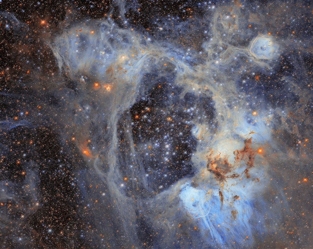
This Hubble Space Telescope image features the picturesque nebula LHA 120-N44, or N44.
NASA, ESA/Hubble, D. Gouliermis
This NASA/ESA Hubble Space Telescope image features a sprawling cosmic vista in the Large Magellanic Cloud, or LMC, the largest of the small galaxies that orbit our Milky Way galaxy. At just 160,000 light-years away, the LMC offers a close look at highly active star birth sites like the one in this image. This photogenic nebula, named LHA 120-N44, or N44, is in the constellation Dorado.
N44 is dominated by two features: a vast central void and a shell of dense, dusty gas. The central void is a ‘superbubble’ spanning roughly 210 by 140 light-years across. The glittering stars at the center of the void are responsible for its creation; through their powerful stellar winds and explosive supernovae, these stars expelled much of the gas from which they were born.
When the stars of N44’s central star cluster swept away this gas, the expelled gas compressed and formed a shell around the superbubble. New stars are forming in this compressed gas shell, making N44 an interesting target for astronomers who are using the nebula to study how stars form in this environment. Their goal is to understand how long it takes from the collapse of cold gas clouds into dense knots to the moment nuclear fusion ignites in the heart of a newborn star.
The data in this image is from an observing program (#14689; PI: Gouliermis) that used Hubble to survey N44 and take a census of its stars, cataloging nearly half a million stars within the cluster as well as interlopers drifting in front of it. Of the stars surveyed, nearly 30,000 are what astronomers call pre-main-sequence stars, which have yet to begin fusing hydrogen into helium in their cores. Astronomers discovered this treasure trove of baby stars thanks to the high sensitivity and fine spatial resolution of Hubble’s instruments that can pick out faint objects in crowded clusters.
The gas shell surrounding the superbubble is energized by ultraviolet radiation from massive stars, causing it to glow and highlighting several distinct features. Each feature within the broader N44 star-forming complex was cataloged by astronomer Karl Henize in the 1950s. One feature is a smaller bubble, cataloged as N44F, that is located near the upper-right corner of this image. N44F is an interstellar bubble blown by the intense stellar winds of a single hot and massive star. As this previously released Hubble closeup shows, the star’s furious winds and radiation have sculpted the surrounding bubble and created pillars of dusty gas.
Hubble’s sensitive observations of the lowest-mass stars in this region open a new window onto star formation in regions that, like the LMC or the galaxies in the early universe, are poor in elements heavier than helium.
In this YouTube video, Dr. Ken Carpenter takes us on a journey through the Nebula, teaching us some of the interesting science behind this famous Hubble image.
Hubble Views N44 Superbubble
N44 is a complex nebula filled with glowing hydrogen gas, dark lanes of dust, massive stars, and many populations of stars of different ages. One of its most distinctive features, however, is the dark, starry gap called a “superbubble,” visible in this Hubble image in the upper central region.
Large N44 Mosaic Image
Download various sizes of Hubble’s large N44 mosaic, including a high resolution, 14,478 x 19,908 pixel (1.6 GB) image
NASA’s Hubble Tracks New Decagon Encircling Saturn’s South Pole
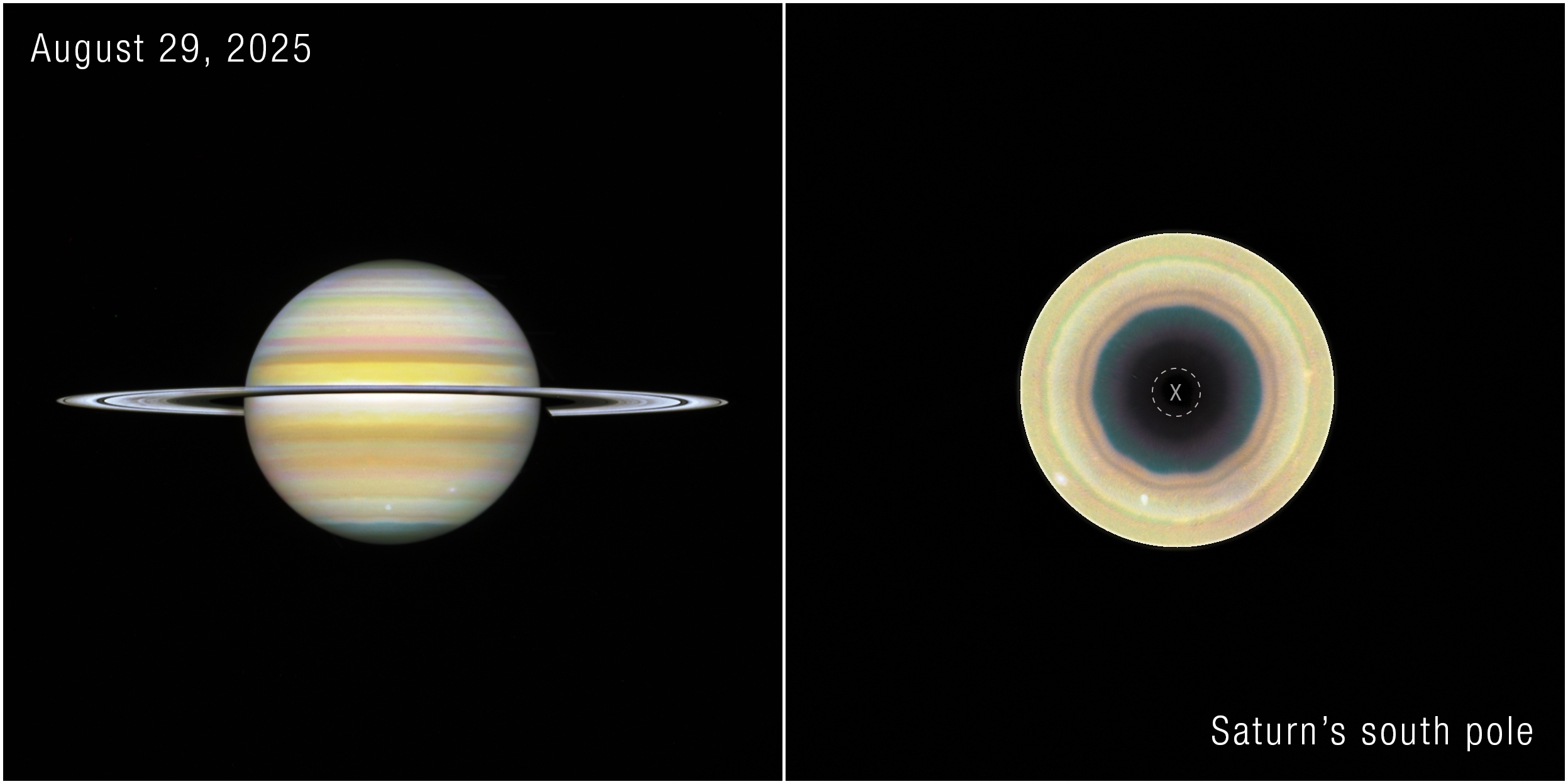
Recent NASA Hubble Space Telescope images show the gas giant Saturn and its southern pole, where astronomers have discovered a 10-sided atmospheric wave. Observations show the decagon extends through multiple layers of Saturn’s atmosphere.
Image: NASA, ESA, STScI, Agustin Sánchez-Lavega (UPV), Amy Simon (NASA-GSFC), Michael Wong (UC Berkeley); Image Processing: Alyssa Pagan
Recent observations with NASA’s Hubble Space Telescope have revealed a giant, evolving, 10-sided atmospheric wave encircling Saturn’s south pole. This discovery marks the first time a large, regular-sided jet pattern has been observed in the planet’s southern hemisphere. The feature appears remarkably similar to Saturn’s famous hexagon at its northern pole, but is also distinctly different, suggesting scientists may be witnessing a new atmospheric phenomenon develop on the iconic gas giant.
The results published Wednesday in the journal Science Advances.
By piecing together several years of Hubble observations dating back to 2023, researchers found subtle hints of the structure beginning to emerge before it became a clearly defined pattern. Those observations were taken as part of Hubble’s Outer Planet Atmospheres Legacy (OPAL) program, which has photographed the outer planets annually for more than a decade.
“We’ve never seen anything quite like this in Saturn’s southern hemisphere,” said Amy Simon, study co-author and OPAL principal investigator, NASA’s Goddard Space Flight Center in Greenbelt, Maryland. “The northern hexagon has been there every time we’ve looked for more than 40 years. This feature is different — it appears to be strengthening, giving us the rare opportunity to watch a giant atmospheric pattern develop.”
The discovery was possible because Saturn’s changing seasons gradually brought the planet’s south pole back into view from Earth, where astronomers who collectively analyze images of Saturn from ground-based observatories first identified it.
Agustín Sánchez-Lavega, lead author of the new study, is a researcher at the University of the Basque Country in Spain. The university manages a website, called Planetary Virtual Observatory Laboratory, that accepts ground-based images of solar system planets contributed by observers all over the world. It was in those images, first in 2024, that Sánchez-Lavega and amateur astronomers Trevor Barry and Jean-Paul Oger noticed a subtle undulating band along the southern pole. Additional 2025 imagery taken from the ground hinted even more strongly toward this decagon structure.
That’s when the Hubble observations come into the picture. Hubble’s view from space offers unmatched image sharpness and spatial resolution over full rotations of Saturn, without smearing by Earth’s atmosphere.
“Given Saturn’s symmetry in its north-south jet stream system, we have been searching for a counterpart to Saturn’s northern hexagon on the south pole in Hubble images since 1990,” Sánchez-Lavega said. “Images from NASA’s Cassini spacecraft, which orbited Saturn between 2004 and 2017, showed no inkling of a long-lived formation, either. The Hubble data confirmed the feature’s presence back to 2023.”
A single filter from NASA’s Hubble Space Telescope distinctly shows a 10-sided wave encircling Saturn’s south pole, labeled “decagon”. An “X” denotes where data was not captured.
Image: NASA, ESA, STScI, Agustin Sánchez-Lavega (UPV), Amy Simon (NASA-GSFC), Michael Wong (UC Berkeley); Image Processing: Alyssa Pagan
The wave sits within one of Saturn’s powerful jet streams and extends through multiple layers of the atmosphere, indicating it is not just a cloud-level feature, but a vertically extended atmospheric structure. The decagon’s apparent position shifts slightly, because Hubble captures images from different wavelengths. Those different wavelengths probe different altitudes in Saturn’s atmosphere.
“The most intriguing part to me is that this seems to have just formed recently,” said Simon. “The question is, why did it suddenly form now when we haven’t seen one before?”
The authors say further study is needed from Hubble and NASA’s James Webb Space Telescope, as well as analysis of computer models, to understand how the decagon formed, how long it may last, and how it compares to the long-lived hexagon in the north.
Hubble’s long duration in operation has allowed astronomers to track changes over time in solar system planets and other astronomical objects as well.
Rather than providing a single snapshot, the OPAL program allows scientists to follow seasonal changes, track short-lived storms, and identify other atmospheric features that evolve slowly over time.
“When we started the OPAL program, we expected compelling surprises, but we didn’t know what to expect specifically,” said Mike Wong, study co-author, University of California, Berkeley. “A lot of the discoveries we see coming from OPAL are not just based on one observation, but on years and years of data. Regular observations over time are enabling a lot of new findings.”
The team plans to continue observing Saturn to determine whether the decagon settles into a long-lived, stable configuration like the northern hexagon or continues to evolve. Future observations also could help scientists determine what drives the wave, what it reveals about the atmospheric dynamics of giant planets throughout the solar system, and how they may relate to those we see here on Earth.
The Hubble Space Telescope has been operating for more than three decades and continues to make ground-breaking discoveries that shape our fundamental understanding of the universe. Hubble is a project of international cooperation between NASA and ESA (European Space Agency). NASA’s Goddard Space Flight Center in Greenbelt, Maryland, manages the telescope and mission operations. Lockheed Martin Space also supports mission operations at Goddard. The Space Telescope Science Institute in Baltimore, which is operated by the Association of Universities for Research in Astronomy, conducts Hubble science operations for NASA.
Recent NASA Hubble Space Telescope images show the gas giant Saturn and its southern pole, where astronomers have discovered a 10-sided atmospheric wave. Observations show the decagon extends through multiple layers of Saturn’s atmosphere.
Decagon on Saturn’s South Pole (Single Filter)
A single filter from NASA’s Hubble Space Telescope distinctly shows a 10-sided wave encircling Saturn’s south pole, labeled “decagon”. An “X” denotes where data was not captured.
High above Earth, thin veils of metallic haze drift through the edge of space. Known as sporadic E layers, these high-altitude “clouds” form from the vaporized dust of burnt-up meteors, earning their name from the unpredictable way they emerge and then dissipate. Now, new results from a NASA sounding rocket — a suborbital research rocket — that flew five detectors through one of these layers simultaneously reveal unexpected complexity in the layer for the first time.
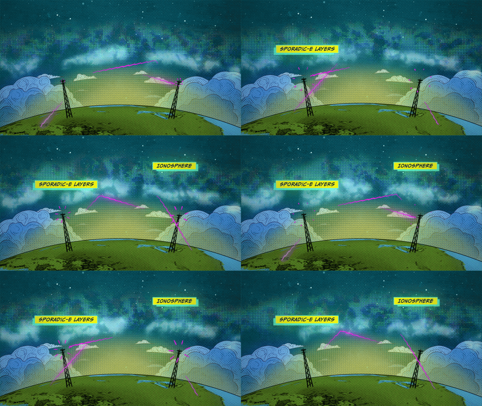
Though invisible to the eye, sporadic E layers make their presence known to the radio signals we rely on for long-distance communication. When present, sporadic E can send those signals ping-ponging off in unexpected directions, rendering the technology temporarily unreliable.
Scientists have long sought a fuller understanding of these radio-disrupting clouds, but until recently, they had only sampled them one narrow slice at a time. The rocket, called the sporadic E Electrodynamics Demonstration, or SpEED Demon for short, launched from NASA’s Wallops Flight Facility in Virginia on Aug. 24, 2022, and demonstrated the first concurrent, multi-point view inside sporadic E. Its results, from a team led by Embry-Riddle Aeronautical University, are described in a new study in the Journal of Geophysical Research: Space Physics.
Sporadic E layers form in the ionosphere, a region of the upper atmosphere beginning around 40 miles (60 kilometers) up where the neutral gases begin to transform into plasma, or ionized gas. Some of the particles there come from meteors, which burn up and leave behind traces of iron, magnesium, and other metals. These metals occasionally clump into dense, cloud-like sheets — the sporadic E layers — that reflect radio waves.
An animated illustration depicts Sporadic-E layers forming in the lower portions of the ionosphere, causing radio signals to reflect back to Earth before reaching higher layers of the ionosphere.
NASA’s Goddard Space Flight Center/Conceptual Image Lab
“Sporadic E layers are, in one sense, giant mirrors of radio frequency waves in the sky,” said Aroh Barjatya, the mission’s principal investigator and a professor of engineering physics at Embry-Riddle in Daytona Beach, Florida.
When a sporadic E layer forms, signals meant to travel out to space can ricochet back toward the ground. Air traffic controllers and marine radio users may pick up distant transmissions as though they were nearby, and radars scanning beyond the horizon can register so-called “ghosts,” or false targets. The effects reach everyday technology, too.
“The biggest source of error in the GPS in your phone, for example, is from the plasma in the ionosphere, and sporadic E layers can contribute to this uncertainty,” said Henry Valentine, the study’s lead author, who conducted the work at Embry-Riddle and is now a researcher at the U.S. Naval Research Laboratory.
Because sporadic E layers hover around 60 miles (100 kilometers) up—too high for weather balloons, too low for satellites — and form and dissipate unpredictably, they have long been the province of sounding rockets, which can be launched on short notice to catch one in the act. But a single rocket flies a single path, taking measurements only along a line. Barjatya likens the situation to viewing a scene through a crack in a wall. One can only observe what is happening along that narrow slit, missing out on the crucial context of whatever is occurring to the left or right of one’s view.
The SpEED Demon mission changed that. The mission was the first to deploy ejectable probes, called dropsondes, inside a sporadic E layer. Once inside, the rocket released four dropsondes that flew away from the main payload and from one another, each measuring the plasma along its own track and beaming its measurements back to ground stations. Together with the main payload, the probes sampled the layer in a total of five places at the same moment.
The SpEED Demon team poses with payload section during testing at NASA’s Wallops Flight Facility.
NASA Wallops/Berit Bland
“Now with multiple sensors, we’ve turned that crack into a picket fence,” Barjatya said.
The data revealed surprising complexity inside the sporadic E layer. Rather than a smooth, dense pancake of metallic particles, the layer that SpEED Demon flew through appeared uneven and structured, shaped by turbulent winds moving through the neutral air around it.
“A lot of times you think of sporadic E as this single sharp density layer, but what we saw in ours is it’s interacting with neutral wind and these swirling atmospheric turbulences,” Valentine said. “Rather than a flat pancake, it’s closer to a cinnamon roll.”
On the way down, the layer even split into two distinct peaks. The team found that shape was consistent with modulation by Kelvin-Helmholtz billows, the curling, wave-like instability that produces breaking-wave patterns in ordinary clouds. Because the flight was unable to measure the local winds and electric fields directly, the researchers are careful to call the billow explanation plausible rather than confirmed.
The SpEED Demon mission was designed as a technology demonstration — a test of whether the dropsonde technique would work at all. It did, and the team was quick to apply it again. Barjatya’s team used a similar multi-probe strategy to launch rockets into the paths of the October 2023 annular eclipse and April 2024 total solar eclipse, studying how the sudden darkness disturbed the upper atmosphere. In June 2025, they flew SpEED Demon’s most direct descendant, Sporadic-E ElectroDynamics, or SEED, into sporadic E layers from Kwajalein Atoll in the Marshall Islands, studying them at lower latitudes. Papers from those missions are in preparation.
A sounding rocket launch testing science instruments for future missions was successfully conducted at 9:16 p.m. EDT, Aug. 23, 2022, from NASA Wallops Flight Facility in Virginia.
NASA
After years of study, sporadic E layers are no longer as unpredictable as they once were. “They have a seasonality to them, with peak occurrence happening in the local summer,” Barjatya said.
Questions about how and when they form are increasingly fine-grained. The new deployable multi-point rocket sensor methodology, along with ground-based measurements, is likely to bring the picture even closer to completion. “The science community as a whole is now in its final stretches of fully understanding these giant radio frequency mirrors in the sky,” Barjatya said.
ByMiles Hatfield NASA’s Goddard Space Flight Center, Greenbelt, Md.
NASA awarded Blue Origin a contract Tuesday to develop the agency’s Mars Telecommunications Network, a next-generation communications system that will enable reliable, high-bandwidth communications and navigation services for current and future Mars missions.
The firm-fixed-price contract has a maximum potential value of approximately $700 million to deliver a high-performance Mars telecommunications orbiter to NASA no later than Dec. 31, 2028.
Blue Origin will design, develop, integrate, launch, and operate the network as a part of the agency’s broader space communications and navigation infrastructure. The architecture will consist of a high-performance telecommunications spacecraft orbiting Mars, transmitting science data, imagery, navigation information, and critical mission communications for spacecraft operating on and around the planet.
The award marks a milestone in NASA’s strategy to expand communications and navigation services beyond Earth and the Moon, establishing the foundation for sustained exploration of Mars in the coming decades.
Under the Artemis program, NASA is sending astronauts to explore the Moon and prepare for missions to Mars. Robotic missions will pave the way for human exploration of the Red Planet, and as these missions expand, demand for data will continue to increase. To meet this need, NASA is pursuing a purpose-built network capable of supporting a growing number of missions while providing greater capacity, reliability, and operational flexibility.
The selection follows NASA’s request for proposal issued in May. As the agency increasingly taps commercial partners for transportation and communications services in Earth orbit and to develop the Moon Base, the Mars Telecommunications Network initiative similarly seeks to harness private-sector capabilities while enabling NASA to focus on exploration and scientific discovery.
The network, managed by NASA’s Space Communications and Navigation program, is expected to be operational at Mars by 2030 and will support both current and future missions to the Red Planet, as NASA ventures deeper into space.
For more information about NASA’s space communications efforts, visit:
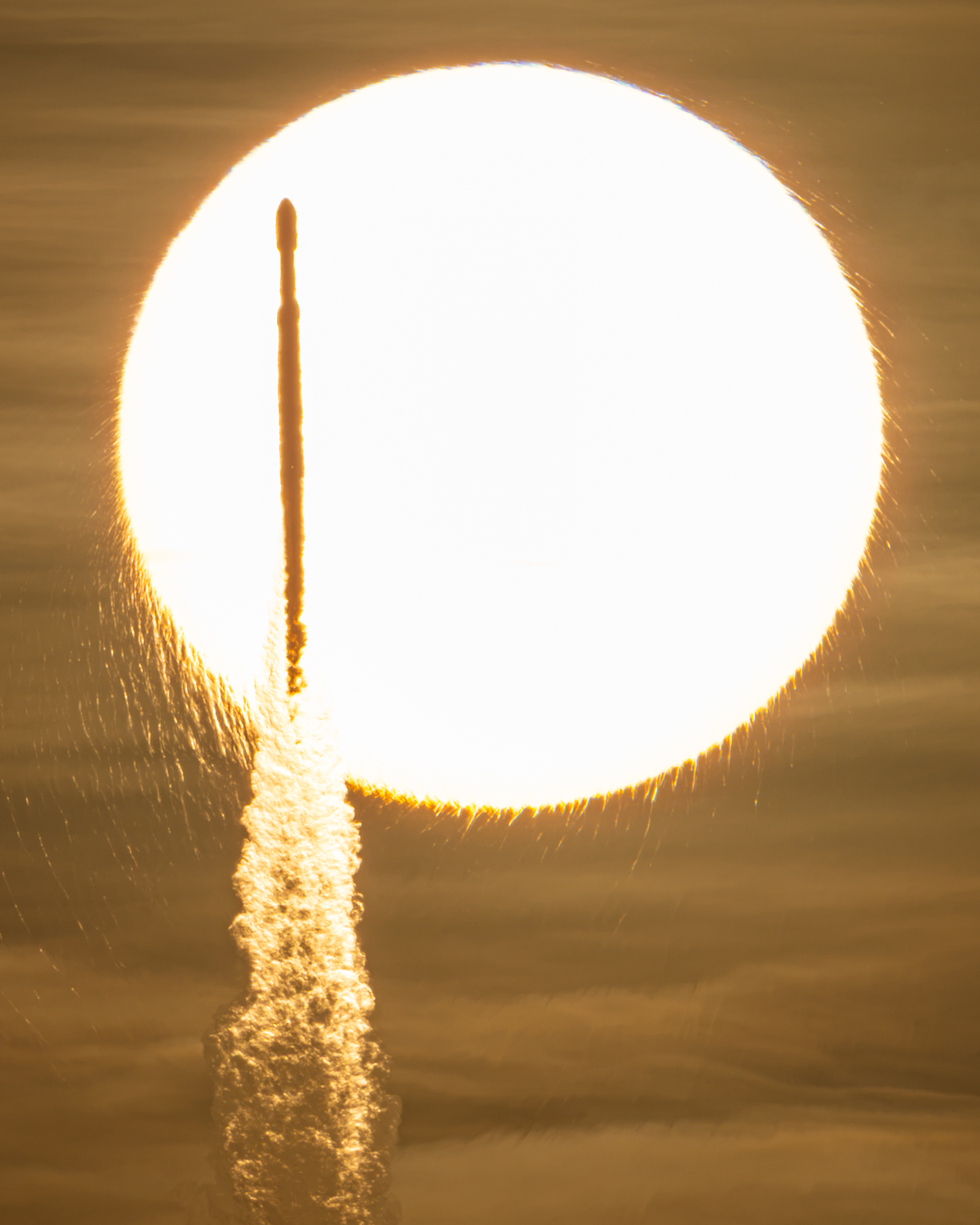
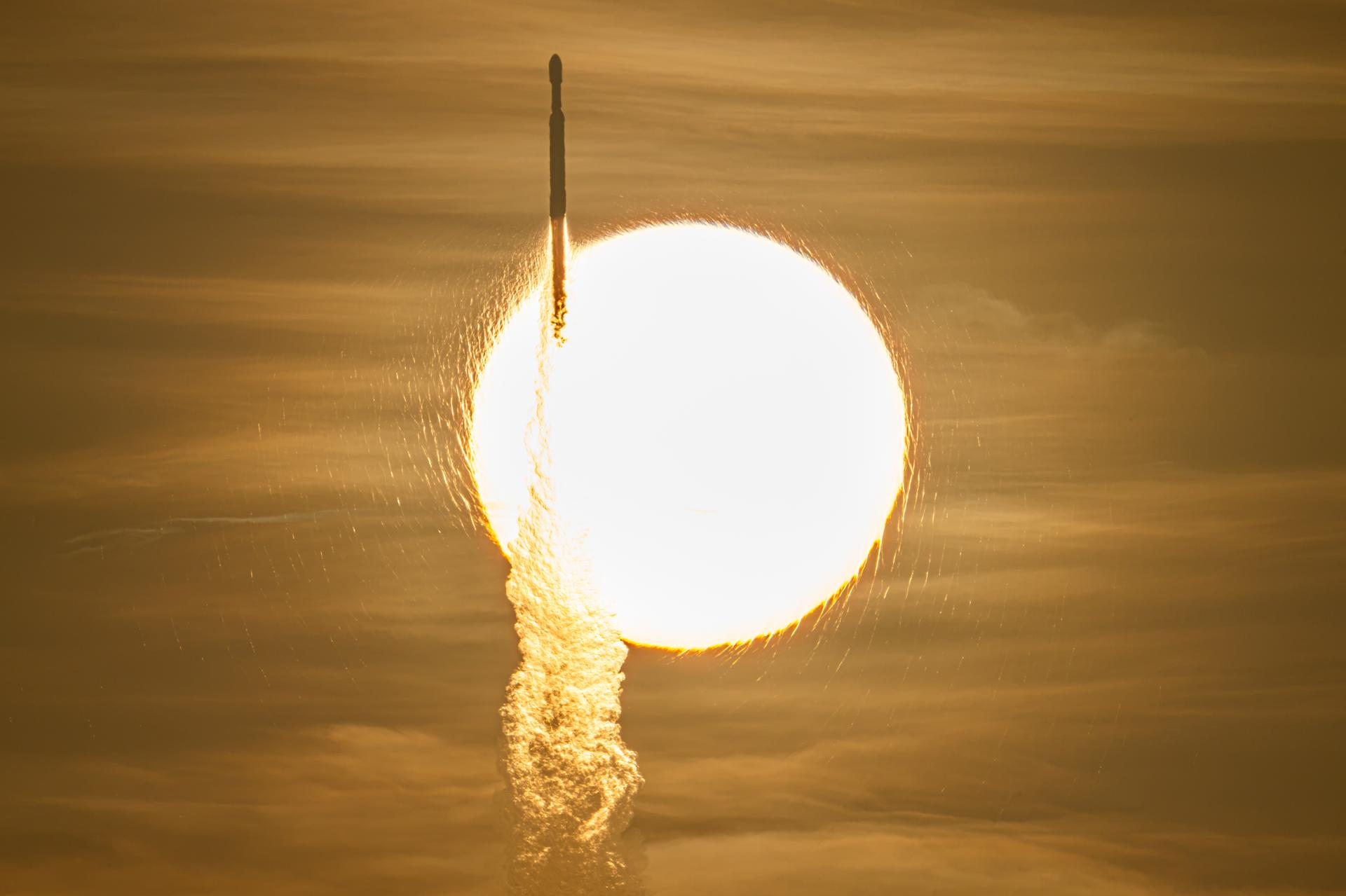
NASA’s Nancy Grace Roman Space Telescope, aboard a SpaceX Falcon Heavy rocket, transits the Sun during launch from the agency’s Kennedy Space Center in Florida on Aug. 30, 2026. Roman is named after the agency’s first chief astronomer.
Roman will survey billions of stars and galaxies with a field of view far larger than Hubble’s, helping scientists study dark energy, exoplanets, and the evolution of the universe.
A SpaceX Falcon Heavy rocket with NASA’s Nancy Grace Roman Telescope on board is seen transiting the sun during launch from Launch Complex 39A, Sunday, Aug. 30, 2026, at NASA’s Kennedy Space Center in Florida.
NASA/John Kraus
Now on a three-month, million-mile journey to its final orbit, NASA’s Nancy Grace Roman Space Telescope will soon reveal the universe’s darkest secrets. The mission launched at 7:26 a.m. EDT Sunday aboard a SpaceX Falcon Heavy rocket from Launch Complex 39A at the agency’s Kennedy Space Center in Florida.
Roman pairs a large field of view with crisp infrared vision to explore vast swaths of the sky and probe deeply into cosmic history. This flagship mission will help astronomers explore dark matter, dark energy, and worlds outside of our solar system, known as exoplanets. Its surveys will support a broad range of research extending far beyond the mission’s main science goals.
“Roman is exactly the kind of success story we want to see across NASA,” said NASA Administrator Jared Isaacman. “Delivered ahead of schedule and on budget, this mission reflects more than a decade of dedication from the NASA workforce and our industry partners. Now, Roman will give us a new atlas of the universe, push the boundaries of discovery, and demonstrate what is possible when America’s space program pairs bold ambition with disciplined execution.”
The ground control team at NASA’s Goddard Space Flight Center in Greenbelt, Maryland, began receiving telemetry data from Roman seven minutes after launch. The Falcon Heavy rocket performed as expected, separating from the observatory 31 minutes into the flight. After separating from the center core, the rocket’s boosters safely returned to the launch site for refurbishment.
“Roman will be a discovery machine that will bring us closer than ever before to answering humanity’s most profound questions about our cosmic history,” said Nicky Fox, associate administrator for the Science Mission Directorate at NASA Headquarters in Washington. “With its large field of view and fast survey speeds, Roman will usher us into a new era of discovery and make the invisible visible, setting the foundation for humanity’s search for life beyond our solar system.”
During launch and early orbit, Roman uses the Near Space Network’s ground stations and relay satellites to exchange tracking, telemetry, and command data with ground controllers. About 70 minutes after launch, the Deep Space Network takes over communications and guides Roman toward the second Sun-Earth Lagrange point, or L2, about one million miles from Earth. Roman connects to that network through the Canberra Deep Space Communication Complex in Australia first. Approximately six hours later it will transfer to the Madrid Deep Space Communication Complex in Spain and then to the Goldstone Deep Space Communication Complex in California, ensuring continuous contact with Roman throughout its journey.
The Roman team also confirmed successful deployment of the observatory’s solar panels and lower instrument sun shade an hour and 23 minutes after launch. Within the upcoming days, Roman’s high-gain antenna and visor-like deployable aperture cover will deploy, ground controllers will initiate the first of two-mid-course corrections, and the Coronagraph Instrument will power on. This instrument will demonstrate the technology that future missions like NASA’s Habitable Worlds Observatory concept could use to image Earth-like planets in the search for life in the universe. Roman’s Coronagraph will take a giant step in that direction by snapping pictures of Jupiter-like planets.
A few weeks into Roman’s voyage, its primary instrument, the Wide Field Instrument, will activate. This 300-megapixel infrared camera has 18 4K detectors, each about the size of a saltine cracker. These detectors collect photons of light that will be decoded into crisp cosmic panoramas. Thanks to the observatory’s rigid design and stable optical performance, it will rapidly scan the sky without needing substantial time between separate observations. The Roman telescope is designed to survey the universe a thousand times faster than NASA’s Hubble Space Telescope.
Throughout the rest of Roman’s three-month commissioning period, scientists will run the instruments through a series of calibrations and tests. NASA anticipates releasing Roman’s first images by early 2027.
Roman will send back 1.4 terabytes of data every day, the highest data rate of any NASA astrophysics mission, so far. Machine learning, artificial intelligence, and citizen scientists will help sift through it and flag significant findings, which astronomers can then study.
“We’ve never been able to view the universe with eyes like Roman’s before,” said Julie McEnery, Roman’s senior project scientist at NASA Goddard. “There’s no telling what more we’ll know and have seen by this time next year.”
Roman is the fourth primary mission NASA has launched on a Falcon Heavy rocket. Earlier this year, the agency’s Launch Services Program worked with SpaceX to accelerate the launch date to accommodate the space telescope’s early completion.
The telescope is managed at NASA Goddard with participation by the agency’s Jet Propulsion Laboratory in Southern California; Caltech/IPAC in Pasadena, California; the Space Telescope Science Institute in Baltimore; and a team of scientists from various research institutions. The primary industrial partners are BAE Systems Inc., L3Harris Technologies, and Teledyne Scientific & Imaging. Contributions to Roman also are made by ESA, JAXA, the French space agency CNES (Centre National d’Études Spatiales), and the Max Planck Institute for Astronomy in Germany.

 Login
Login