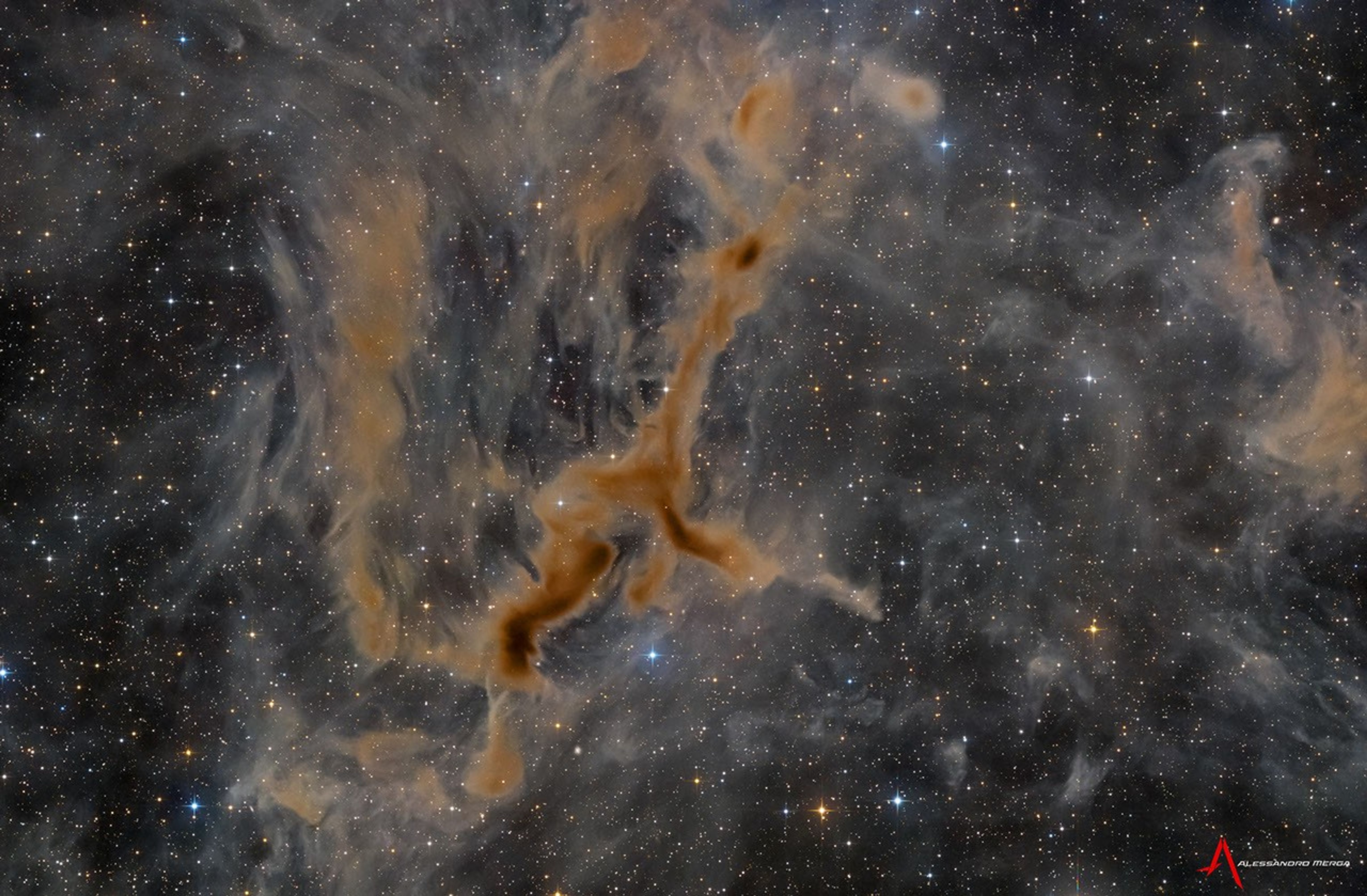
Discover the cosmos! Each day a different image or photograph of our fascinating universe is featured, along with a brief explanation written by a professional astronomer.
Comet NEOWISE Rising Over the Adriatic Sea
Explanation: This sight was worth getting out of bed early. Just over four years ago, Comet C/2020 F3 (NEOWISE) rose before dawn to the delight of northern sky enthusiasts awake that early. Up before sunrise on July 8th, the featured photographer was able to capture in dramatic fashion one of the few comets visible to the unaided eye this century, an inner-Solar System intruder that has become known as the Great Comet of 2020. The resulting video detailed Comet NEOWISE from Italy rising over the Adriatic Sea. The featured time-lapse video combines over 240 images taken over 30 minutes. The comet was seen rising through a foreground of bright and undulating noctilucent clouds, and before a background of distant stars. Comet NEOWISE remained unexpectedly bright for over a month, with its ion and dust tails found to emanate from a nucleus spanning about five kilometers across.
How do scientists studying space with data from a telescope hundreds of thousands of miles away know that what they are seeing is real? A new NASA project, Artifact InSPECtor, invites you to find out – and by doing so, to help missions like Euclid and NASA’s new Nancy Grace Roman Space Telescope answer fundamental questions about our universe.
“It’s really cool that we can help teach computers new skills,” said nine-year-old Maeve F. after trying out Artifact InSPECtor. Participants of all ages, including those as young as Maeve, can visit the project to learn how they can contribute to science by training artificial intelligence to remove errors in telescope data.
Here’s how it works.
The Euclid space telescope, a powerful observatory built by ESA (European Space Agency) with critical contributions from NASA, is collecting light from millions of distant galaxies across the universe. It will soon be joined by NASA’s Nancy Grace Roman Space Telescope, a complementary observatory that will capture a similar number of galaxies after it begins science operations, but at different distances and densities across the sky. Together, these telescopes promise to help scientists answer questions about the expansion of the universe and dark energy – the mysterious force causing this expansion.
To collect data to answer these questions, each telescope uses a special instrument called a spectrograph that works like a prism: it splits the light from each galaxy, even very distant ones, into a rainbow of colors. By studying these rainbow patterns, called spectra, scientists can figure out how far away each galaxy is, what kinds of stars it contains, and even information about the supermassive black holes at their centers.
But before that can happen, there’s a problem to solve.
Telescope data contains many “artifacts” – the general name scientists use for signals that come from things other than real astronomical objects like galaxies or stars. Artifacts can be created by light glinting off the telescope’s housing, cosmic rays striking the detector, quirks in the camera or electronics, or other sources. It’s a bit like when a smudge on your phone’s camera lens shows up in a photo, or when a glare from the Sun blocks part of your picture.
To find and remove these artifacts, astronomers have created artificial intelligence (AI) tools that learn to recognize them, similar to how your phone recognizes faces in photos. But recognizing artifacts in data from relatively new instruments is challenging work for the AI, which doesn’t always distinguish them accurately
That’s where you come in! As a volunteer with Artifact InSPECtor, you’ll look at real space telescope data from Euclid and, starting in early 2027, the Nancy Grace Roman Space Telescope. The project will teach you how to recognize artifacts in data from these telescopes. The work you do will then be used to improve the instructions guiding the AI tool. Working together, you, the AI, the scientists, and these powerful space telescopes will learn more than ever before about how our universe works.
If you want to teach computers new skills and help discover the mysteries of dark energy, use your smartphone, tablet, or computer to visit Artifact InSPECtor and begin today: https://go.nasa.gov/3Uyrguy.
Examples of what artifacts can look like in space telescope data. The blue areas indicate pixels that the AI model thinks are invalid. Artifact InSPECtor volunteers will learn how to verify whether the machine got it right.
Credit: Image data from the ESA/Euclid Q1 Data release. Image processing by Aimee Schechter and Bharath C. Nagam.
Learn More and Get Involved
Artifact InSPECtor
Train the tools used to remove artifacts from the data collected by space telescopes. For anyone with a smartphone or laptop.
X-ray: NASA/CXC/SAO; Optical: NASA/ESA/STScI; Infrared: NASA/ESA/CSA/STScI; Image Processing: NASA/CXC/SAO/L. Frattare and J. Major
Two galaxies merge at a furious rate in this Aug. 25, 2026, image of the II Zw 096 system. This and several other images of both visually and scientifically interesting galaxies were released by NASA’s Chandra X-ray Observatory and other telescopes.
Chandra X-ray data (magenta) pinpoint powerful black hole activity and hot gas, while optical data (blue and white) from NASA’s Hubble Space Telescope and infrared data from NASA’s James Webb Space Telescope illuminate vast stellar nurseries hidden behind interstellar dust. Systems like II Zw 096 show us how powerful galaxy collisions shaped the early universe.
NASA’s SpaceX Crew-12 members suit up in the Neil A. Armstrong Operations and Checkout Building at the agency’s Kennedy Space Center in Florida ahead of launch to the International Space Station on Feb. 13, 2026. From left, Roscosmos cosmonaut Andrey Fedyaev, NASA astronauts Jack Hathaway and Jessica Meir, and ESA (European Space Agency) astronaut Sophie Adenot.
Credit: NASA/Kim Shiflett
Media are invited to hear from NASA’s SpaceX Crew-12 astronauts during a news conference beginning at 2:45 p.m. EDT, Wednesday, Sept. 16, from the International Space Station.
NASA astronauts Jessica Meir and Jack Hathaway, ESA (European Space Agency) astronaut Sophie Adenot, and Roscosmos cosmonaut Andrey Fedyaev will discuss their upcoming return to Earth. Learn where to watch online:
Media interested in participating must contact the newsroom at NASA’s Johnson Space Center in Houston no later than 5 p.m., Tuesday, Sept. 15, at 281-483-5111 or jsccommu@mail.nasa.gov. To ask questions, media must dial into the news conference no later than 10 minutes prior to the start of the call. A copy of NASA’s media accreditation policy is online.
Crew-12 joined Expedition 74/75 crew members aboard the space station and contributed to hundreds of experiments to prepare for human exploration beyond low Earth orbit and to benefit humanity on Earth. Research included studying pneumonia-causing bacteria to improve cardiovascular treatments, on-demand intravenous fluid generation for future space missions, and how physical characteristics may affect blood flow during spaceflight.
The crew will depart the space station after the arrival of Crew-13 and a short handover period. Ahead of Crew-12’s return, mission teams will review weather conditions at the splashdown sites off the coast of California prior to departure from station.
For more than 25 years, people have lived and worked continuously aboard the International Space Station, advancing scientific knowledge and making research breakthroughs not possible on Earth. The space station helps NASA understand and overcome the challenges of human spaceflight, expand commercial opportunities in low Earth orbit, and build on the foundation for long-duration missions to the Moon, as part of the Artemis program, and to Mars.
Learn more about the International Space Station, its research, and crew, at:
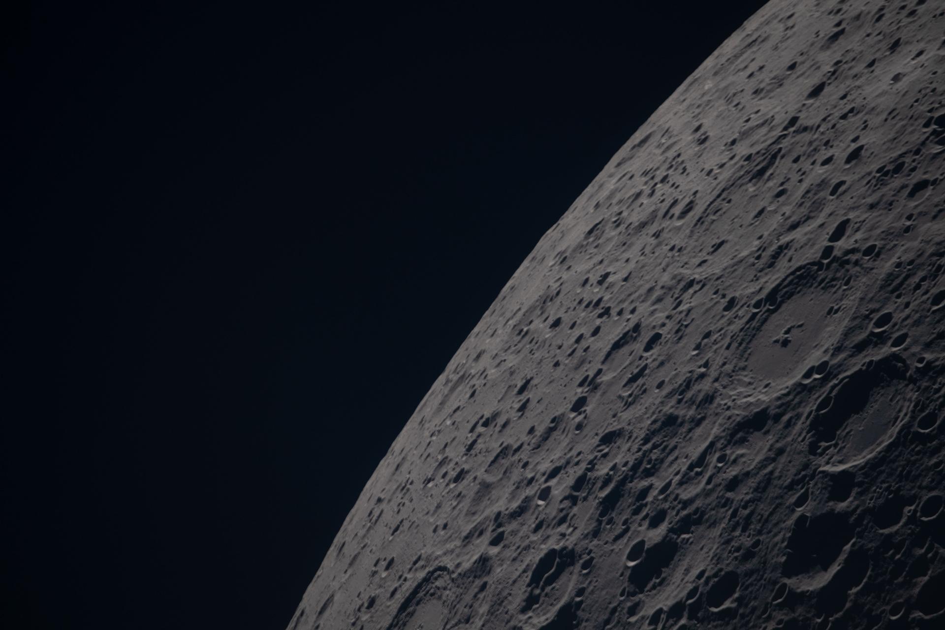
Poynting crater and Keeler crater are visible side by side in the lower right portion of this image of the Moon’s far side highlands. Poynting, positioned above, is a large impact crater with a well-defined rim and relatively smooth interior, indicative of material that has settled following the initial impact. Just below it, Keeler crater appears slightly smaller, with a sharply outlined rim and a more textured interior shaped by subsequent impacts and ejecta. Both features lie within the densely cratered far side highlands, preserving a record of ancient impacts that have shaped the lunar surface over billions of years.
NASA
The science from every Moon rock sample, lunar dataset, and discovery produced through NASA’s Artemis program will be shared by the agency with the global scientific community. That commitment is upheld by all 71 countries that have signed the Artemis Accords, a set of principles for safe and transparent civil space exploration.
NASA put those principles into practice by hosting a two-part virtual workshop series that began July 28 and concluded Sept. 8, focusing on one key tenet of the Artemis Accords: the timely release of scientific data to the public and the international scientific community.
“As we return humans to the Moon, our Artemis efforts will help us unlock the full potential of scientific discovery through transparency, collaboration, and accessibility,” said Jacob Bleacher, chief exploration scientist at NASA. “We are making data, tools, and results freely available, and inviting the Artemis Accords partners to innovate with us and share their data as well, accelerating our understanding of lunar processes and laying the groundwork for human space exploration for the Moon, Mars and beyond.”
The two recent workshops added to discussions led by the ISRO (Indian Space Research Organisation) in May, when signatories first explored ways to advance open data practices and created common ground for deeper conversations on open data. NASA split its follow‑on discussion about data sharing into two virtual sessions, so technical experts around the world could take part.
The agency hosted its first session on open science principles and implementation practices. It promoted interoperability and collaboration among signatories and advanced reproducibility, accessibility, and transparency in scientific work, including in NASA’s Artemis program.
The second session focused on tools for open science, providing Artemis Accords signatories with a working model to reference as they build or refine their own data-sharing frameworks.
“NASA is committed to leading by example when it comes to open science,” said Andrew Mitchell, deputy chief science data officer for NASA’s Science Mission Directorate, whose office leads the agency’s open science efforts. “These workshops gave our Artemis Accords partners practical tools and a shared foundation to build on as we move forward together.”
NASA presented the Planetary Data System, one of the agency’s primary archives for planetary science data, openly available lunar data, data visualization and analysis tools, and the system’s data information model standard, offering a real-world example of how NASA structures, curates, and shares scientific data with the world.
Across both sessions, NASA shared practices developed over years of stewarding scientific data and opened the floor to technical experts across the Artemis Accords community, reflecting a deliberate effort to build alignment at the working level.
“Advances in technology help enable open science, but technology alone is insufficient,” said Mitchell. “Open science requires a shift to a more transparent and collaborative scientific process, which will increase the pace and quality of scientific progress. Scientific processes and results should be as open and repeatable as possible to encourage further study.”
In 2020, NASA and the State Department joined with seven other founding nations to establish the Artemis Accords in response to the growing interest in lunar activities by both governments and private companies. They introduced the first set of practical principles aimed at enhancing the safety and coordination between like-minded nations as they explore the Moon, Mars, and beyond, committing nations to:
explore peaceably and transparently
render aid to those in need
enable access to scientific data
ensure activities do not interfere with those of others
preserve historically significant sites and artifacts by developing best practices
By signing the Artemis Accords, nations open the door to opportunities for future lunar exploration with NASA, advancing humanity’s return to the Moon, and shaping the Golden Age of space exploration and innovation.
The curving, parallel mountain ridges of the Sierra Madre Oriental are an eye-catching feature of northeastern Mexico’s landscape. The spot where these folds nestle up against Mexico’s second-largest metropolitan area captured the attention of an astronaut aboard the International Space Station, who took this photo on August 26, 2026.
Monterrey, the capital of the state of Nuevo León, is an industrial hub supporting heavy industries such as ironworks and steelworks, as well as manufacturing facilities for goods ranging from textiles to processed foods to glass and plastics. The metropolitan area is home to 5.3 million people, according to the 2020 census. And while the city has seen overall population growth since 1990, the number of people living within 5 kilometers (3 miles) of the city center has declined, researchers have found—a trajectory shared with many of Mexico’s metropolitan areas.
In Monterrey’s case, urban expansion runs up against some unforgiving terrain. Along the city’s southern edge, layers of limestone, deposited in the late Mesozoic era and then folded between about 80 and 50 million years ago, form the Sierra Madre Oriental. Over millions of years, weaker rock layers have eroded away, leaving behind the distinct ridgelines that bound Monterrey today.
The Río Santa Catarina carves through the mountains and onto the semiarid floodplain where the city lies. Because of the dry environment, the river carries little to no water for much of the time. But its channel is crucial for collecting runoff from summer rains and serves as an important natural area for plant and animal life within the city.
The river runs through Monterrey’s urban core and between several island-like protrusions of folded rock. One of these is the Sierra Las Mitras, a state nature reserve established in 2000. The mountain ridge rises approximately 1,500 meters (4,900 feet) over the city and provides a haven for wildlife. As conditions become cooler and wetter with higher elevations, vegetation turns from cacti and thorny shrubs on lower rocky slopes to oak and pine forests higher on the ridge. Cerro de la Silla (Mount Silla or Saddle Hill) is another prominent feature of the landscape, contrasting with the built environment.
Near the city’s border with the Sierra Madre Oriental sits Universidad de Monterrey, a host venue for the NASA Space Apps Challenge. This annual hackathon will take place in November 2026 in person and virtually at sites around the world. Participating teams use NASA and partner agency data to tackle challenges in fields such as software development, astrophysics, space exploration, and agriculture.
Astronaut photograph ISS075-E-70481 was acquired on August 26, 2026, with a Nikon Z9 digital camera using a focal length of 400 millimeters. It is provided by the ISS Crew Earth Observations Facility and the Earth Science and Remote Sensing Unit at NASA Johnson Space Center. The image was taken by a member of the Expedition 75 crew. The image has been cropped and enhanced to improve contrast, and lens artifacts have been removed. The International Space Station Program supports the laboratory as part of the ISS National Lab to help astronauts take pictures of Earth that will be of the greatest value to scientists and the public, and to make those images freely available on the internet. Additional images taken by astronauts and cosmonauts can be viewed at the NASA/JSC Gateway to Astronaut Photography of Earth. Story by Lindsey Doermann.
NASA, IBM Launch AI Foundation Model for Lunar Science
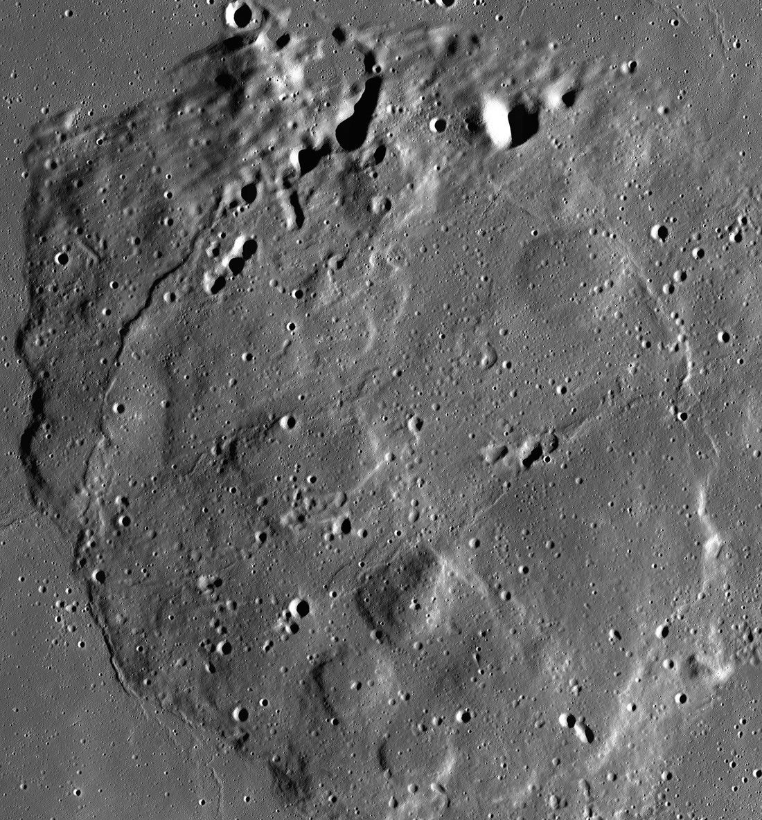
A 10-image mosaic captured by NASA’s Lunar Reconnaissance Orbiter’s Narrow Angle Camera between June 2012 and April 2016 showing the volcanic feature Mons Rümker and its surrounding mare plains.
NASA/GSFC/Arizona State University
NASA is bringing artificial intelligence to the study of the Moon, helping researchers transform how they analyze the Moon’s surface. In an ongoing collaboration with IBM Research and several academic institutions, NASA has launched the NASA-IBM Lunar Foundation Model, among the first open-source AI models built specifically for lunar science. The model, trained primarily on data from NASA’s Lunar Reconnaissance Orbiter (LRO), is hosted publicly on Hugging Face for anyone to use, with the complete codebase available on GitHub for testing and experimentation.
The NASA-IBM Lunar Foundation Model supports the next generation of lunar science by helping researchers quickly analyze vast quantities of data to better understand the Moon’s surface. Using the model as a mapping tool, researchers can rapidly develop actionable strategies for evaluating the Moon’s rugged surface, understanding its geological past, and planning future lunar research.
“NASA has spent decades building an extraordinary scientific record of the Moon, but collecting data is only part of the job,” said Kevin Murphy, chief science data officer and acting chief data and AI officer at NASA Headquarters in Washington. “We also have to make data easier for scientists to explore and use. The NASA-IBM Lunar Foundation Model shows what’s possible when we bring AI to NASA’s petabytes of scientific data. That’s a real opportunity we see with AI: turning large-scale data into new discoveries.”
Unlike traditional models that require building and training specialized algorithms from scratch for specific tasks, foundation models are pre-trained on vast, unlabeled datasets. The broad knowledge they acquire through pre-training allows them to generalize across multiple scientific domains through quick fine-tuning, making foundation models both versatile and efficient in accelerating scientific research.
The NASA-IBM Lunar Foundation Model shows what’s possible when we bring AI to NASA’s petabytes of scientific data.
Kevin Murphy
NASA Chief Science Data Officer and Acting Chief Data Officer/Chief AI Officer
Data collected by NASA’s LRO over the past 17 years was well-suited for training this foundation model because it covers most of the lunar surface in detail. The data produced from the LRO mission is larger than all other NASA planetary missions combined, capturing an almost seamless, high-resolution mosaic of the entire Moon. The NASA-IBM model was trained on roughly 2 million image tiles from this dataset, comprising more than 1 million high-resolution camera images at 1-meter resolution and nearly 964,000 multispectral images at 100-meter resolution. The model also was trained on high-resolution Moon imagery and terrain data from multiple other missions such as NASA’s GRAIL (Gravity Recovery and Interior Laboratory), NASA’s Lunar Prospector, and JAXA’s (Japan Aerospace Exploration Agency) Selenological and Engineering Explorer.
Because the foundation model is already pre-trained on this dataset, planetary scientists can adapt the model to many different lunar research tasks such as mapping craters, spotting young volcanic features, and estimating where ice may exist near the lunar poles by using only small amounts of labeled data. For researchers who study the Moon’s polar ice, the NASA-IBM model can help them estimate where ice patches are likely to be stable, on and below the surface. Dark areas like the Moon’s permanently shadowed regions remain cold enough to trap and preserve ice for up to billions of years. Studying these areas offers insight into the Moon’s history and presents an opportunity to map potentially usable resources for future space exploration.
The NASA-IBM model reproduces patterns of lunar ice prospectivity (scaled from blue to yellow), shown at four locations (left) near the Moon’s pole. Top row: reference ice prospectivity map of Mons Mouton near the lunar south pole; middle row: predictions from the ConvNeXt model; bottom row: predictions from the NASA-IBM model. The NASA-IBM model preserves many fine-scale prospectivity patterns in the reference data.
NASA/IBM Research
While the Moon is thought to no longer be volcanically active, it once experienced dynamic geological processes. For researchers studying lunar volcanism, the NASA-IBM model accelerates the identification of unusual looking volcanic features known as irregular mare patches. Because these structures appear relatively young, they challenge established timelines for lunar cooling, and mapping them could help scientists piece together a more accurate understanding of the Moon’s thermal evolution.
The model also can map surface features, such as craters, more efficiently than manual methods. Every crater is formed by an impact, making crater counts and measurements essential for dating the lunar surface and reconstructing solar system history. The foundation model helps speed up the process of identifying and measuring craters, allowing scientists to focus on interpreting findings and determining their implications for exploration.
These Lunar Reconnaissance Orbiter images show the Moon’s surface near Einstein crater before (left) and after (right) a SpaceX rocket body impact. The NASA-IBM Lunar Foundation Model detected existing craters (blue outlines) and highlighted the newly formed impact crater (red box). Because the post-impact image was excluded from pre-training, this test demonstrates how the model can be fine-tuned to recognize novel surface changes between observations. This approach can help scientists automatically detect natural impacts and surface changes across vast lunar datasets, though varying lighting conditions between orbits may influence smaller crater visibility.
NASA/IBM Research
Overall, the model matched or exceeded the performance of several other strong baseline models across all evaluated tasks, achieving comparable results on crater mapping and segmentation of irregular mare patches, while demonstrating a clear advantage on estimating polar ice stability.
The NASA-IBM Lunar Foundation Model is part of the agency’s Office of the Chief Science Data Officer’s strategy for AI for science — a larger, ongoing collaboration between NASA and IBM aimed at using advanced AI to explore our planet and solar system. It joins a growing collection of AI models developed through this partnership, including:
The Prithvi Models: a family of models pre-trained on Earth observation data and designed to support applications such as disaster monitoring, flood mapping, crop yield prediction, and hurricane prediction.
The Surya Model: a heliophysics model trained on high-resolution solar observation data to predict space weather phenomena such as solar flares which can disrupt power grids and satellite operations.
Within NASA, the Impact AI team at the agency’s Marshall Space Flight Center in Huntsville, Alabama, collaborated with scientists in the agency’s Science Mission Directorate Planetary Science Division, NASA’s Goddard Space Flight Center in Greenbelt, Maryland, and NASA’s Ames Research Center in California’s Silicon Valley, to build the NASA-IBM model. The model is an example of open science in action, uniting experts from NASA, industry, and academia to turn raw data into a resource for lunar discovery. To support the global research community, the team released comprehensive machine learning-ready pre-training datasets and benchmark collections alongside the model, which is integrated into the open-source TerraTorch toolkit. Supported by a companion paper available on Hugging Face, this open release ensures reproducible research and equips scientists worldwide to build, compare, and refine AI models for the future of lunar exploration.
The science team, assembled by NASA Headquarters, included experts from the Universities Space Research Association in Huntsville, Alabama; the SETI Institute in Silicon Valley, California; the University of Maryland, Baltimore County in Catonsville, Maryland; Howard University in Washington, D.C.; NASA’s Science Mission Directorate Planetary Science Division; NASA Ames; and NASA Goddard.
For more information about NASA’s strategy of developing foundation models for science, visit:
Discover the cosmos! Each day a different image or photograph of our fascinating universe is featured, along with a brief explanation written by a professional astronomer.
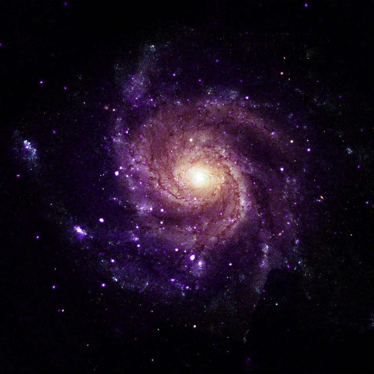
M83: The Southern Pinwheel
Explanation: Beautiful and bright spiral galaxy M83 lies some twelve million light-years away, near the southeastern tip of the very long constellation Hydra. Prominent spiral arms traced by dark dust lanes and blue star clusters lend this galaxy its popular name, the Southern Pinwheel. Still, reddish star forming regions that dot this cosmic pinwheel’s spiral arms have suggested another nickname, the Thousand-Ruby Galaxy. A mere 40,000 light-years across, smaller than the Milky Way, M83 is a member of a group of galaxies that includes active galaxy Centaurus A. In fact, the core of M83 itself is bright at x-ray energies, showing a high concentration of neutron stars and black holes left from an intense burst of star formation. This sharp, groundbased telescopic view also features foreground Milky Way stars and distant background galaxies.
The Republic of Djibouti will sign the Artemis Accords during a ceremony at 11 a.m. EDT, Monday, Sept. 14, at NASA Headquarters in Washington, becoming the 72nd country signatory.
NASA Deputy Administrator Matt Anderson will host Ambassador of Djibouti to the United States Mohamed Siad Douale for the ceremony, together with U.S. State Department Assistant Secretary for African Affairs Frank Garcia.
In 2020, during the first Trump Administration, the United States, led by NASA and the State Department, joined with seven other founding nations to establish the Artemis Accords, responding to the growing interest in lunar activities by both governments and private companies.
The accords introduced the first set of practical principles aimed at enhancing the safety, transparency, and coordination of civil space exploration on the Moon, Mars, and beyond.
President Donald Trump presents an executive order establishing the United States Space Academy during an event to award the Congressional Space Medal of Honor to the Artemis II crew as Michael Kratsios, director of the Office of Science and Technology Policy, left; Kevin Hassett, director of the National Economic Council, third from left; and NASA Administrator Jared Isaacman, right, applaud, Friday, Aug. 28, 2026, at NASA’s Johnson Space Center in Houston.
Credit: NASA/John Kraus
Less than two weeks after an Executive Order was signed to create the first United States Space Academy, NASA-led work is in full swing to make the academy a reality and shape the future of America’s aerospace workforce and leadership.
NASA Administrator Jared Isaacman chaired the first Presidential Commission on the United States Space Academy meeting on Sept. 9. Following that meeting, NASA published a Request for Information Thursday seeking input from governors or their designees interested in hosting and sponsoring the up-and-coming academy in their state.
“Our first Commission meeting made clear how much talent and commitment we have behind President Trump’s vision for the U.S. Space Academy,” said NASA Administrator Jared Isaacman. “I’m grateful to our partners across government for getting right to work. Now, with the RFI underway, states across the country have an opportunity to help us shape a legacy institution built for America’s future in space.”
Isaacman and Deputy Administrator Matt Anderson welcomed key commission members from multiple agencies and organizations to NASA Headquarters in Washington for a collaborative Commission discussion. Participants included U.S. Secretary of War Pete Hegseth, Director of the National Economic Council Kevin Hassett, Secretary of the United States Air Force Troy Meink, and U.S. Chief Technology Officer Ethan Klein, representing Director of Office and Technology Policy Michael Kratsios, along with representatives from the U.S. Office of Management and Budget, the National Security Council, and the White House.
During the meeting, commission members began working through the structure and priorities of the proposed U.S. Space Academy, including its governance, curriculum, service commitments, partnerships, and implementation.
“The location of the U.S. Space Academy is foundational to its success,” said Anderson. “We’re asking states to bring their strongest vision — the infrastructure, the partnerships, and the community that can compete with the elite options this caliber of student will have and match the boundless ambition of our future space leaders.”
The commission’s 120-day mandate to develop recommendations for President Trump on how to establish the academy and build the technical talent and leadership pipeline needed to support America’s long-term goals in space began when the President signed the Executive Order on Aug. 28.
Responses to the RFI will help inform the commission’s path forward to selecting a location for the institution and are due by 6 p.m. EDT on Monday, Oct. 26. An ambitious timeline is outlined in the request, calling for a groundbreaking no later than 2027, temporarily hosting the first 300 students in 2028, and a permanent location in operation by 2031.
Each state is allowed one submission to the Announcement via its governor’s designee. In addition to details about resources available to support the academy, input sought on the potential campus includes:
Location information
Site readiness
Environmental and regulatory considerations
Proximity and supporting ecosystems
A fact sheet on the U.S. Space Academy is available on The White House website.
NASA’s Life-Saving Technology Where Cell Signals Can’t Go
Rescued after more than four hours in the water, Easton Barrett (center, red shorts) and his friend were picked up by the U.S. Coast Guard thanks to a personal locator beacon (PLB). The devise sends a distress signal to satellites that are relayed back to Earth, launching a rescue operation.
Credits: Easton Barrett
Memorial Day weekend 2024 started with a blue sky and a mild three- to four-foot chop in the water off the Gulf Coast of Mississippi — a perfect day for a fishing competition. A team of five was about 40 miles offshore checking their sonar, and 30 seconds later the boat was gone. They were in the water struggling to pull on life jackets and grab the coolers as they bobbed up. When a boat sinks, survivors can be virtually invisible amid the vast expanse of water.
When their fishing trip went wrong, Easton Barrett had the only mobile phone and no cell service. He recorded a brief farewell, planning to put his phone in a cooler in hopes someone would find it.
Another team member activated a personal locator beacon (PLB) that had been stowed at the last minute, which sent a distress signal to the Search and Rescue Satellite-Aided Tracking (SARSAT) technology carried by multiple satellites in Earth orbit. In the SARSAT system, developed partly by NASA, an emergency signal containing the transmitter’s location is directed to the nearest available ground station.
406 megahertz is the wavelength dedicated for PLB distress signals. On the annual 406 Day, Easton Barrett posts videos and messages on his social media accounts to help raise awareness about essential survival gear.
Credit: ACR
A mission control center then alerts rescue coordination centers to mobilize search and rescue crews. For Barrett and his crew, that was a Florida Coast Guard boat.
“Ever since, I have tried to teach others about safety on the water and in the outdoors by using a PLB,” said Barrett. “If that will save one life, it’s worth the effort.”
A beacon like the one that saved his crew, a registered ResQLink PLB developed by ACR Electronics Inc. of Fort Lauderdale, Florida, also notifies the device owner’s emergency contact, indicating a distress call was activated. All emergency beacons must meet the same requirements to ensure they work when needed. Every rugged, buoyant, handheld devices have a five- to 10-year battery life.
SARSAT began operations in 1982, becoming an international collaboration in 1985. The flight and ground technologies used globally were originally developed at NASA’s Goddard Space Flight Center in Greenbelt, Maryland. Now there are 62 satellites in the program and 45 nations contributing services, from operating ground stations to providing rescue crews. More than 63,000 lives have been saved.
Turning on a ResQLink View PLB from ACR Electronics will automatically “ping” orbiting satellites that send location and GPS information
to the nearest search and rescue station. Whether on land or water, the appropriate resources will be dispatched to help anyone in distress
anywhere in the world.
Credit: ACR
SARSAT by the Numbers
The Search and Rescue Satellite-Aided Tracking system developed over several decades by NASA and other government agencies saves lives on land or at sea.
1982 — the start of U.S. operations
1985 — the start of international operations
62 operational satellites
45 nations contributing services
63,000+ lives saved
One rescue in 2024 demonstrates how it all comes together.
40 miles off the Mississippi Gulf Coast
5-person team participating in a fishing competition
30 seconds for a boat to sink
200 pounds of bait dumped to make a cooler buoyant
3 close encounters with wildlife, likely sharks and eels
4 hours in the water
1 personal locator beacon
1 Coast Guard rescue boat
5 lives saved
“If it has anything to do with NASA, it's got to be awesome.”
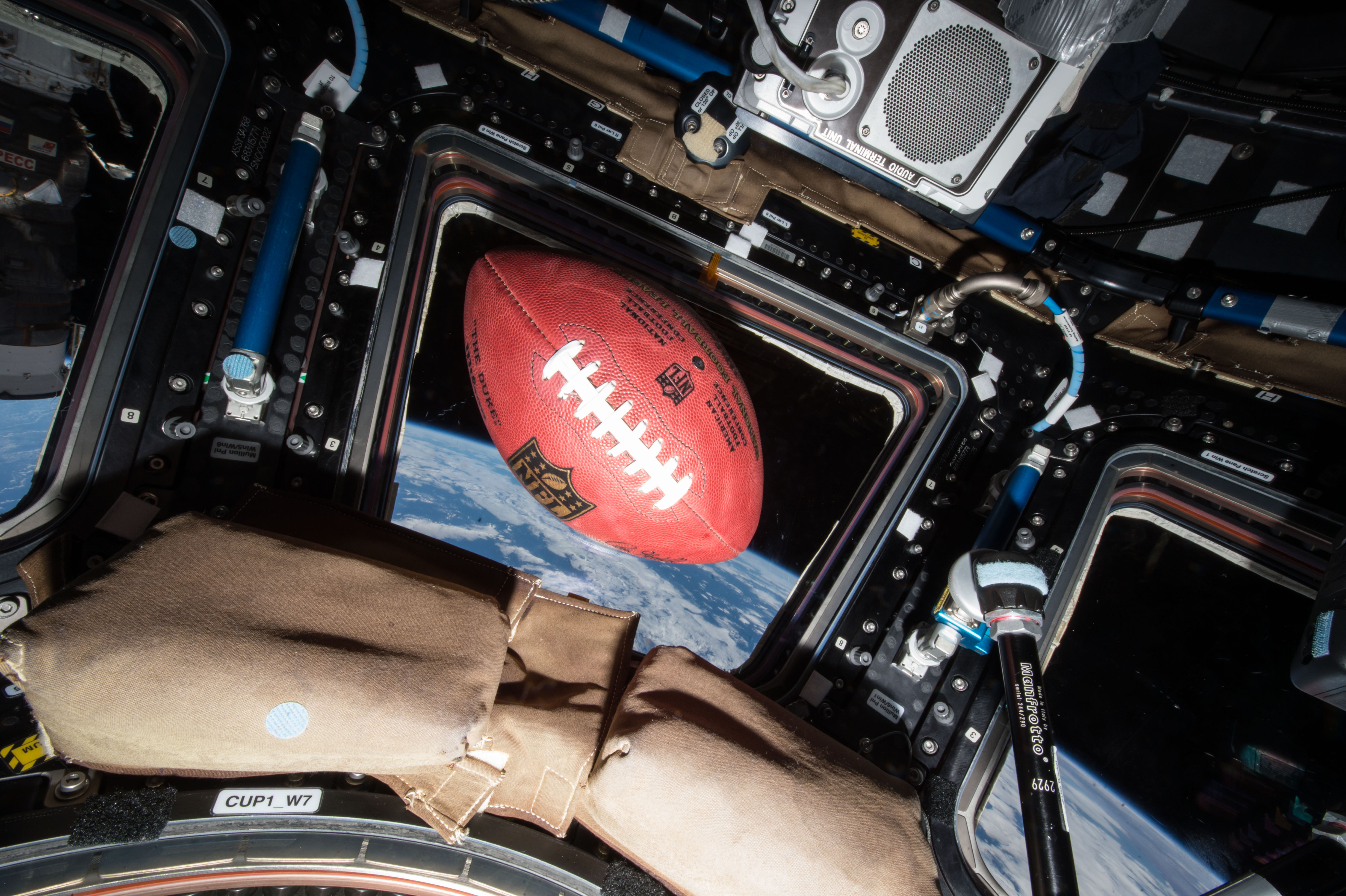
A football floats in microgravity aboard the International Space Station, high above the Earth.
Credit: NASA
Through a new collaboration between NASA and the National Football League (NFL), the agency will soon bring America’s strengths in space exploration and aeronautics innovation to the football field.
NASA will conduct flyovers, astronaut appearances, and fan engagement at NFL games across the United States as part of its new Inspiration Tour.
“This is the first season NASA is taking part in flyovers at NFL games, bringing the excitement of America’s space program directly to fans across the country,” said NASA Administrator Jared Isaacman. “We’re returning to the Moon, building a Moon Base, advancing fission-powered spacecraft, and pushing the boundaries in aeronautics, science, and discovery. Achieving those ambitions will take the very best of America, and partnering with the NFL gives us an incredible platform to inspire the next generation to look up and imagine the possibilities.”
NASA participation is targeted for the following games. Additional details will be released prior to each game, and more dates may be added:
1 p.m., Sunday, Sept. 13: Pittsburgh Steelers vs. Atlanta Falcons in Pittsburgh
1 p.m., Sunday, Sept. 20: Baltimore Ravens vs. New Orleans Saints in Baltimore
1 p.m., Sunday, Oct. 4: Philadelphia Eagles vs. Los Angeles Rams in Philadelphia
1 p.m., Sunday, Oct. 11: New York Jets vs. Cleveland Browns in East Rutherford, New Jersey
Flyovers scheduled at some of the games will showcase NASA’s fleet of aircraft, which are used for high-speed testing, high-altitude research, astronaut training, and more. Regularly flying the aircraft maintains the health of the fleet and publicly demonstrates new technologies that may be applied to future commercial air travel.
With stops across the nation and led by Isaacman, NASA’s Inspiration Tour convenes academic, industry, and public sector stakeholders to connect the agency with the people, technologies, and organizations that drive American leadership in space.
The tour will culminate in MAX POWER, a public exposition of American air and space innovation, Nov. 7 and Nov. 8, on and near the agency’s Kennedy Space Center in Florida. Held in honor of America’s historic 250th anniversary, the multi-day, family-friendly event will showcase the next-generation aircraft, spacecraft, autonomous vehicles, and technologies that will help define the future of transportation in air and space.
For more information about MAX POWER and the agency’s missions, visit:
ESA/Webb, NASA & CSA, F. Peißker, J. Lu, F. Yusef-Zadeh, N. B. Sabha, C. Chan
A brilliant concentration of stars takes center stage in this Aug. 11, 2026, image taken by NASA’s James Webb Space Telescope. Webb observed IRS 3, a star near the end of its life cycle, located within this starfield. Webb’s mid-infrared data revealed the clear signature of oxygen-rich silicate dust, as well as, for the first time, water, in its surrounding dust envelope.
Discover the cosmos! Each day a different image or photograph of our fascinating universe is featured, along with a brief explanation written by a professional astronomer.
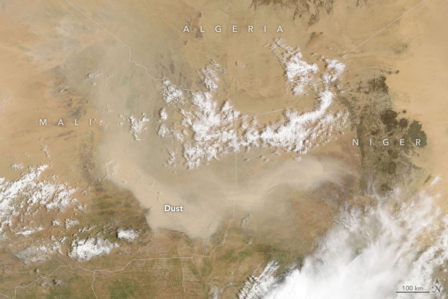
A dust storm obscures the ground in Mali in this image, acquired with the MODIS (Moderate Resolution Imaging Spectroradiometer) on NASA’s Terra satellite on September 5, 2026.
NASA Earth Observatory/Lauren Dauphin
As summer winds down in West Africa, so does much of the region’s dust activity. Dust storms can still occur, though, as one did in early September 2026, when a plume covered parts of Mali and neighboring countries.
The MODIS (Moderate Resolution Imaging Spectroradiometer) on NASA’s Terra satellite captured this image on September 5, 2026. According to Tianle Yuan, an atmospheric scientist at NASA’s Goddard Space Flight Center, storms like this one are often associated with haboobs—powerful dust storms driven by strong convective winds.
In the days after this image was acquired, a wider satellite view showed aerosols from the region moving westward and spilling over the Atlantic Ocean. However, a full transatlantic crossing is unlikely. Such crossings are more common from late spring through summer, when the Saharan Air Layer—a dry, dusty mass of air—can carry dust thousands of miles westward from Africa, riding high in the atmosphere.
Looking ahead, the developing El Niño could reshape these patterns. For instance, Yuan noted that the phenomenon can affect dust over the Sahel and Mali by shifting the Intertropical Convergence Zone and altering convection patterns, though the influence cuts both ways. Drier conditions can leave more loose sediment available for winds to lift, but less convective activity also means fewer intense storms (haboobs) to kick up large dust plumes in the first place. “The connection can be real,” Yuan said, “but hard to pin down for individual events.”
NASA Earth Observatory image by Lauren Dauphin, using MODIS data from NASA EOSDIS LANCE and GIBS/Worldview.Story by Kathryn Hansen.
A NASA Launch Services (NLS) II contract has been awarded by the agency to Relativity Space Inc., and its Terran R launch service in accordance with the contract’s on-ramp provision. The Terran R launch service will be available to NASA’s launch services to use for future missions.
The NLS II contracts are multiple-award, indefinite-delivery/indefinite-quantity contracts with an ordering period through June 2030 and an overall period of performance through December 2032. The NLS II contracts include an on-ramp provision that provides an opportunity annually for new launch service providers to compete for future missions and allows existing contractors to introduce launch vehicles not currently on their NLS II contracts.
The NLS II contracts support the goals and objectives of the agency’s Human Spaceflight Mission Directorate, Science Mission Directorate, and the Research and Technology Mission Directorate. Under the contract, NASA also can provide launch services to other government agencies, such as the National Oceanic and Atmospheric Administration.
NASA’s Launch Services Program Office at the agency’s Kennedy Space Center in Florida manages the NLS II contracts. For more information about NASA, visit:
X-ray: NASA/CXC/Univ. of Alabama/M. Muhibullah et al.; Optical: NASA/ESA/STScI; Image Processing: NASA/CXC/SAO/N. Wolk
Using NASA’s Chandra X-ray Observatory, scientists have discovered a new class of objects behaving unlike any they have seen before. Astronomers suggest these newly spotted objects in other galaxies may help solve not one, but two long-standing questions in astrophysics.
These mysterious objects give off unusually low-energy X-rays but intense levels of ultraviolet radiation. This discovery is featured in a paper published Wednesday in Nature Astronomy.
“We’ve never encountered a group of objects that act like this,” said Mustafa Muhibullah of the University of Alabama who led the study. “Of course, the next step was to try to figure out what these things are.”
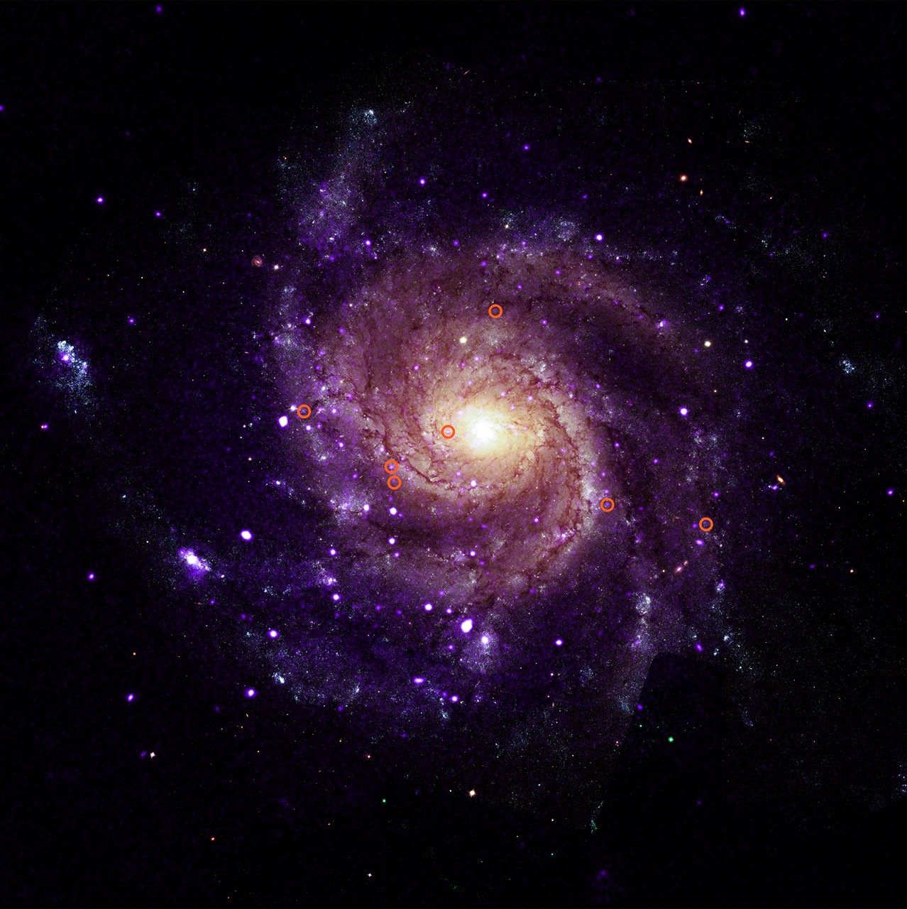
M101 with illustrated circles calling out seven of the newly-discovered objects.
X-ray: NASA/CXC/Univ. of Alabama/M. Muhibullah et al.; Optical: NASA/ESA/STScI; Image Processing: NASA/CXC/SAO/N. Wolk
The researchers found a total of 84 of these “hypersoft X-ray sources” – so named because they give such low-energy X-rays – in the six different galaxies they searched, using data openly available to the public in the Chandra archive. Two of the galaxies are spirals, M31 (the Andromeda galaxy) and M101 (the Pinwheel galaxy), while the other four are ellipticals. They found hypersoft X-ray sources both in regions of active star formation and areas where there are older stars.
The team spotted the sources by finding objects that appeared in Chandra images taken at the lowest X-ray energies but vanished in higher-energy images. That means these objects give off far more low-energy X-rays than high-energy ones. Because low-energy X-rays border energetic ultraviolet radiation on the electromagnetic spectrum, the researchers determined that these sources are producing large amounts of energetic ultraviolet radiation as well.
It is unclear what types of objects are responsible for these low-energy X-rays and intense ultraviolet radiation. The team thinks they most likely involve a black hole, neutron star, or white dwarf pulling material from a companion star. The material pulled from the companion star is heated up to produce X-rays before falling onto the white dwarf or neutron star, or into the black hole. Such binary systems have been seen before, but not with such bright ultraviolet radiation and low-energy X-rays.
The discovery suggests that there may be large populations of binary systems with energetic ultraviolet radiation that have been undetected until now.
“These clandestine X-ray sources are actually among the most energetic objects in galaxies, and they could be solving two cosmic mysteries at once,” said Muhibullah.
Scientists think that some white dwarf systems pulling material from companion stars may eventually explode as a supernova – known as a Type Ia – that is critical for measuring the expansion of the universe. These supernovae played a key role in discovering that this expansion is accelerating. Astronomers have been looking for the stars that turn into Type Ia supernovae for many years, so far without success.
“If we could find a way to spot these Type Ia supernova explosions before they go off, that would be really important,” said co-author Jimmy Irwin, also of the University of Alabama. “Right now, we study them after they’ve exploded, and astronomers have struggled to understand what is actually ignited.”
The other mystery these hypersoft X-ray sources might explain is what strips electrons from gas between the stars in some galaxies. This stripping of electrons is important to probe because it can affect how quickly stars form and influence the life cycles of galaxies. Hot, massive stars play a role, but they do not completely explain what is causing this stripping. The intense levels of ultraviolet radiation from the hypersoft X-ray sources may play a vital role.
Why were these hypersoft X-ray sources not found until now? In addition to the low-energy X-ray output, which is very difficult for X-ray telescopes to detect, the high-energy ultraviolet radiation is readily absorbed by helium and hydrogen gas that fills the space between the stars, creating a nearly impenetrable barrier to look through.
“By combing through the Chandra archive, we were able to eliminate what used to be a blind spot for telescopes,” said co-author Rosanne Di Stefano of the Center for Astrophysics | Harvard & Smithsonian. “That’s how we found what appears to be a new class of cosmic objects with remarkable qualities.”
NASA’s Marshall Space Flight Center in Huntsville, Alabama, manages the Chandra program. The Smithsonian Astrophysical Observatory’s Chandra X-ray Center controls science operations from Cambridge, Massachusetts, and flight operations from Burlington, Massachusetts.
This release features a composite image of a spiral galaxy, M101; one of six identified galaxies housing a new class of mysterious objects that give off unusually low-energy X-rays.
In this composite image, M101 faces us directly. It has multiple arms in shades of purple, spiraling clockwise around a golden yellow core. Scattered along and between the arms are scores of tiny specks in white and purple. Most of those specks are pairs of stars, but seven of them are a mystery.
To casual observers, the unusual objects are visually indistinguishable from the other specks of light in the galaxy. An annotated version of the composite image is included in this release, with red circles around the mysterious specks for easy identification.
These mystery specks behave like no other class of object discovered before. The curious objects give off X-rays of such low energy, they in fact produce large amounts of ultraviolet radiation, as UV radiation borders X-rays on the electromagnetic spectrum. Searching images of galaxies with low-energy X-rays in the Chandra Observatory archive, scientists have found a total of 84 such objects spread across M101 and five other galaxies. They have dubbed these mysterious objects “hypersoft X-ray sources.”
Preparations for Next Moonwalk Simulations Underway (and Underwater)
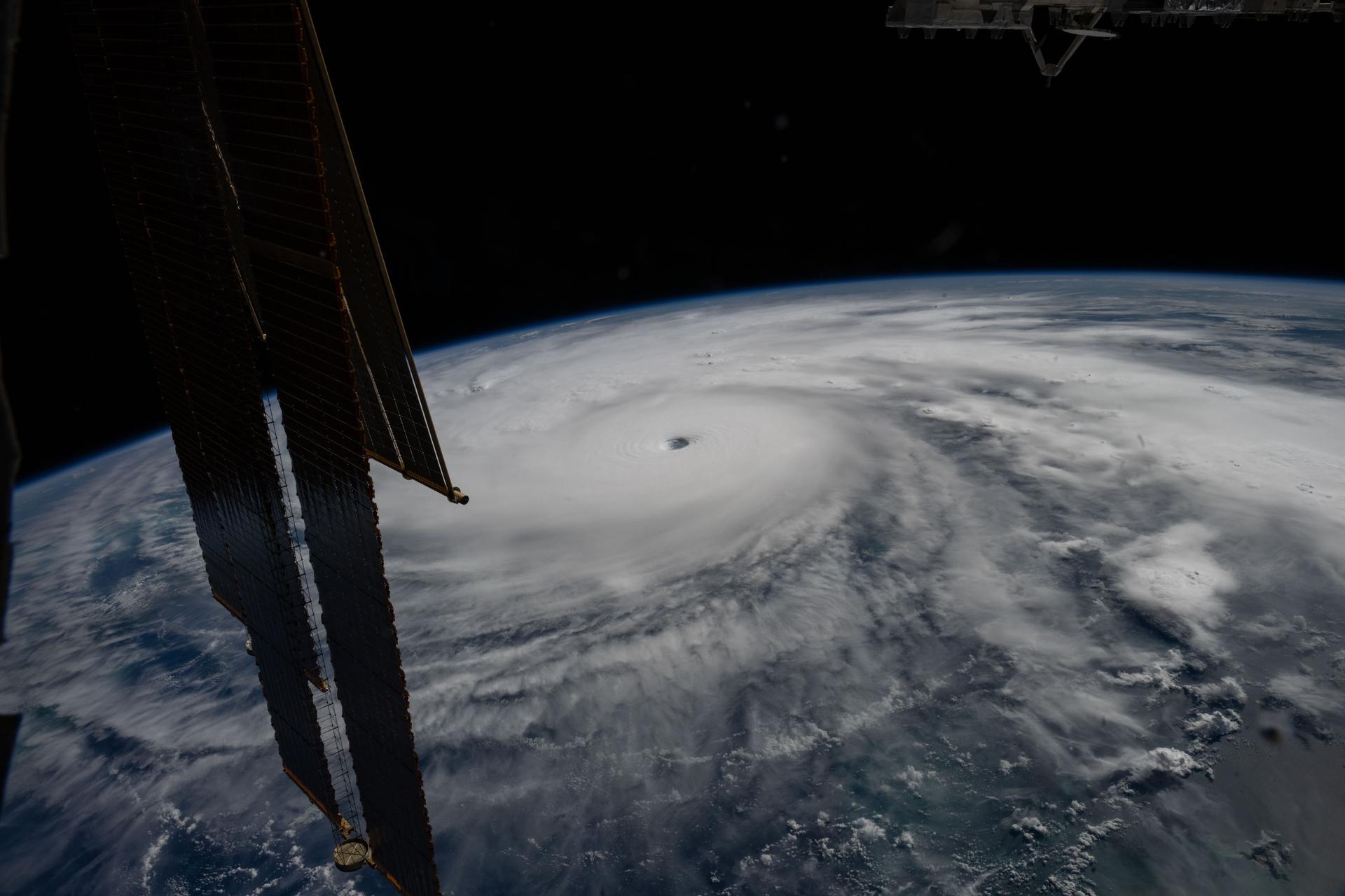
Hurricane Melissa is seen 50 miles south of Jamaica in this photograph taken from the International Space Station on Oct. 28, 2025.
NASA
Last November, NASA and its European partners launched the Sentinel-6B satellite to improve hurricane forecasts, help protect infrastructure, and benefit commercial industries, including shipping. The satellite now is flying 30 seconds behind its predecessor, Sentinel-6 Michael Freilich. Both satellites are providing precise sea level height measurements during what oceanographers expect to be a historic El Niño, a naturally occurring oceanic phenomenon in which warmer-than-usual Pacific waters shift global weather patterns.
The two satellites make up the Copernicus Sentinel-6/Jason-CS (Continuity of Service) mission, the latest in a series of ocean-observing radar altimetry missions that have been monitoring Earth’s changing seas continuously since the early 1990s.
The data each satellite is collecting will not only allow scientists to better understand this year’s El Niño but will also help them create more accurate hurricane predictions.
“This El Niño was a late-bloomer,” said Josh Willis, Sentinel-6B’s project scientist at NASA’s Jet Propulsion Laboratory in Southern California. “It didn’t kick off until the middle of the year and is just now reaching a strength similar to what we’ve seen in the satellite record during significant El Niños in 1997 and 2015. We expect it to be big, and it’s already having big impacts.”
El Niños generally scramble weather patterns tied to rainfall and storms, including hurricanes. They also redistribute heat in the ocean, which affects sea level. Normally, Earth’s warmest ocean waters sit along the equator in the western Pacific. During El Niño, weakened winds, which usually blow westward along the equator, result in heat spreading east toward South America. The change in ocean heat shifts hurricane activity from the Atlantic to the Pacific Ocean.
Predicting hurricane strength
On July 15, Sentinel-6B began delivering low-latency data to scientists that could be used for weather predictions. That data will take some time to work its way into the research models on which meteorologists and climate scientists rely, but when it does, those improved models could save lives.
Data from Sentinel-6 satellite missions feeds into hurricane tracking algorithms used by federal and state agencies. Those predictions can activate disaster response efforts, mobilizing resources ranging from sandbag placement to National Guard activation. They also can lead to evacuation orders that require quick but well-informed decisions about logistics at a local level. More severe events may require engaging larger organizations, such as the Federal Emergency Management Agency.
A tropical storm can take a week or more to become a hurricane and make its way to a coastline, but a hurricane can rapidly intensify in the 48 hours prior to landfall, leaving planners little time to prepare.
“Hurricanes have been known to speed up quickly at the last moment, so the window in which to decide what to do is short,” said Deirdre Byrne, an oceanographer and altimetry expert with the National Oceanic and Atmospheric Administration (NOAA). “The goal is to forecast how much and how rapidly intensification will happen so that officials can make the right calls.”
Each Sentinel-6 satellite measures ocean height, as well as the size of waves and marine wind speed, using a radar altimeter, which bounces thousands of radar pulses a second off the crests and troughs of waves. Ocean height varies from place to place and provides insight into the ocean’s heat content, since warm water expands. That, in turn, helps forecast how fast hurricanes will grow.
Among the measurements Sentinel-6 is gathering, Byrne is most anticipating the ocean height data, which she plans to begin incorporating into the current Satellite Ocean Heat Content Suite algorithm by the end of the year.
“In terms of data quality, the Sentinel-6 missions are unparalleled,” Byrne said.
Together, the missions are also extending a precise dataset deep into its fourth decade. This record of sea level observations traces back to the TOPEX/Poseidon mission, which launched in 1992, and continues through to the present day with Sentinel-6 Michael Freilich. Sentinel-6B will take over for its predecessor as the reference satellite for global sea level measurements later this year.
“The key is consistency, measuring the same way, every time,” said Severine Fournier, Sentinel-6B deputy project scientist, JPL. “That’s what lets us predict hurricanes, and, in turn, protect coastal communities and infrastructure.”
More about Sentinel-6B
Sentinel-6 Michael Freilich, named after a former director of NASA’s Earth Science Division, is one of two satellites that compose the Copernicus Sentinel-6/Jason-CS mission.
Sentinel-6/Jason-CS, a part of the European Union’s Earth observation program called Copernicus, was jointly developed by ESA (European Space Agency), EUMETSAT (European Organisation for the Exploitation of Meteorological Satellites), NASA, and NOAA, with funding support from the European Commission and technical support on performance from the French space agency CNES (Centre National d’Études Spatiales). Spacecraft monitoring and control, as well as the processing of all the altimeter science data, is carried out by EUMETSAT on behalf of the European Union’s Copernicus Programme, with the support of all partner agencies.
NASA JPL, a division of Caltech in Pasadena, contributed three science instruments for each Sentinel-6 satellite: the Advanced Microwave Radiometer, the GNSS-RO, and the Laser Retroreflector Array. NASA also contributed launch services, ground systems supporting operation of the agency’s science instruments, the science data processors for two of these instruments, and support for the United States members of the international Ocean Surface Topography Science Team.
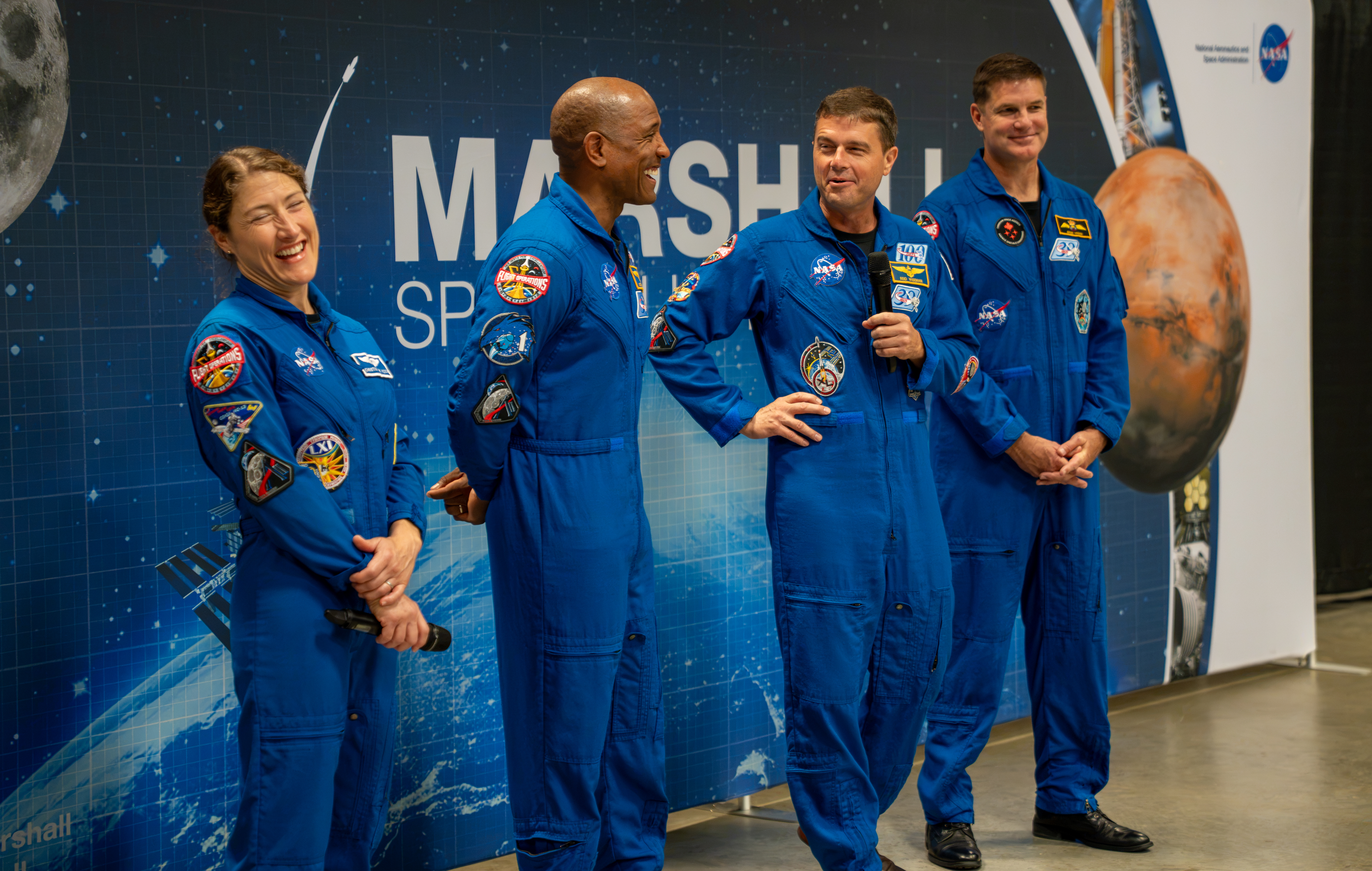
The crew of NASA’s Artemis II mission – NASA astronauts Christina Koch, Victor Glover, and Reid Wiseman and CSA (Canadian Space Agency) astronaut Jeremy Hansen – visited Huntsville, Alabama, Sept. 1, 2026, where they met with the NASA workforce at NASA’s Marshall Space Flight Center. The event gave the crew an opportunity to share firsthand experiences from their mission, reflect on their time in space, and connect with the workforce that supported the mission through an engaging question-and-answer session.
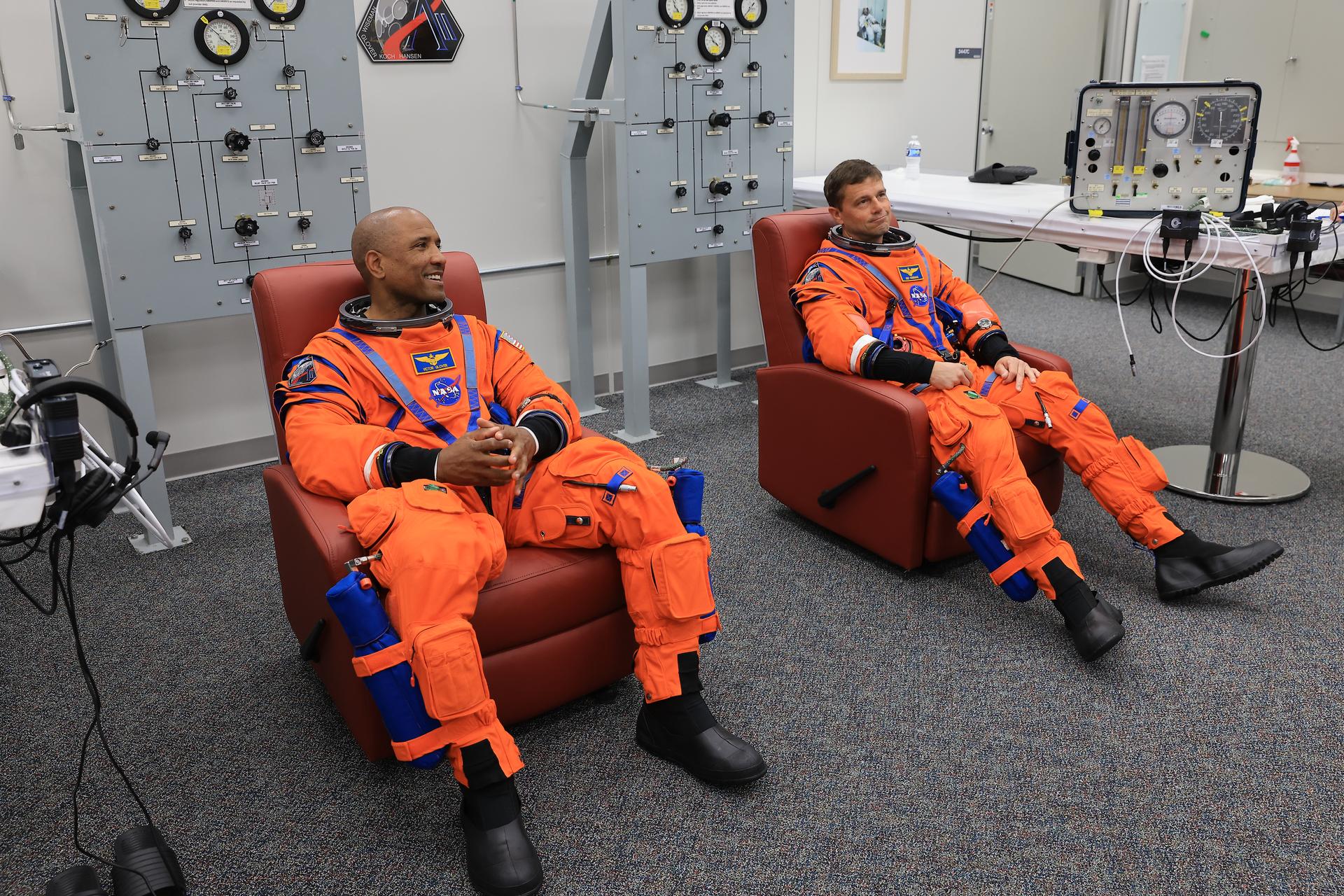
From left, NASA astronauts Victor Glover, Artemis II pilot, and Reid Wiseman, Artemis II commander, conduct leak checks on their spacesuits inside the crew suit-up room in the Neil A. Armstrong Operations and Checkout Building at the agency’s Kennedy Space Center in Florida on Wednesday, April 1, 2026, ahead of the Artemis II test flight.
Credit: NASA/Kim Shiflett
Following their landmark Artemis II mission earlier this year, distinguished NASA astronauts Victor Glover and Reid Wiseman are transitioning in September to emeritus status at the agency’s Johnson Space Center in Houston.
In an emeritus role, individuals with a high degree of technical and professional knowledge can continue to support the agency by donating their time to train and mentor the current workforce. This allows the agency to maintain access to top talent in a specialized consultant role, while simultaneously providing the individual with the flexibility to pursue other opportunities.
“I’ve had the privilege of knowing Reid and Victor for years, and both exemplify the leadership, character, and commitment that define NASA at its best.” said NASA Administrator Jared Isaacman. “Reid commanded Artemis II after previously spending 165 days aboard the International Space Station, while Victor brought his experience as a naval aviator, test pilot, and Crew-1 astronaut to his role as pilot. Together, they took on one of the most challenging missions in human spaceflight and helped return America to the lunar environment. As Reid and Victor transition to emeritus status, I’m grateful they will continue sharing what they learned with our astronauts, flight controllers, and engineers as we prepare for Artemis III in 2027 and the missions that follow.”
Glover will support aerospace, leadership, and public service efforts as he transitions within and outside of NASA. He’s committed to transferring his knowledge of Orion and its spacecraft systems, among other expertise, to future Artemis missions.
“As I grow into this new role, NASA and spaceflight remain a meaningful part of my journey of service,” said Glover. “I’m excited to keep uplifting my friends and cheering them on as they reach for the Moon. Together, we’ll keep pushing boundaries and inspiring the next giant leap.”
Wiseman is set to share his spaceflight experience with colleagues ahead of the agency’s Artemis III mission in low Earth orbit to test rendezvous and docking capabilities between Orion and commercial human landing systems.
“There is no better place to work, and there are no better people to work with, than those in this agency,” said Wiseman. “NASA gave me tremendous responsibility, supported me through two space missions, and my time as chief astronaut, and was always there for my family when we needed it most. I’m thrilled to continue serving future missions and programs through the emeritus program.”
“Reid and Victor’s commitment to exploration, steady leadership, and service to our astronaut corps and our nation have made a lasting impact,” said Vanessa Wyche, director of NASA’s Johnson Space Center in Houston. “Throughout their careers, they have each brought excellence, humility, and purpose to every role they have held at NASA. Their contributions have helped advance our mission and inspire those around them, leaving a legacy that will continue to shape the future of human spaceflight. We are immeasurably grateful for all they have given to NASA and are glad that this is not the end of their journey with the agency.”
“Reid and Victor are trusted teammates whose professionalism, calm leadership, and unwavering commitment to NASA have strengthened our office and inspired everyone around them,” said Scott Tingle, chief of the Astronaut Office at Johnson. “As they transition into their emeritus roles, they leave a legacy of operational excellence that will continue shaping the astronaut corps for years to come. We’re grateful that they will still be part of our community, sharing their experience and insight as they begin this next chapter.”
Among their many accomplishments at NASA, as Artemis II crew members, Glover and Wiseman were two of the four astronauts to first launch on top NASA’s SLS (Space Launch System) rocket aboard the Orion spacecraft for a mission around the Moon. Following a 10-day mission with crewmates NASA astronaut Christina Koch and CSA (Canadian Space Agency) astronaut Jeremy Hansen, they safely splashed down on April 10 as the first humans to travel to lunar orbit in more than 50 years, ultimately flying farther in space than anyone had before.
Support and knowledge transfer from both Glover and Wiseman is critical for the upcoming Artemis III mission as NASA prepares to return American astronauts to the lunar surface on the Artemis IV mission in 2028.

 Login
Login