A NASA Launch Services (NLS) II contract has been awarded by the agency to Relativity Space Inc., and its Terran R launch service in accordance with the contract’s on-ramp provision. The Terran R launch service will be available to NASA’s launch services to use for future missions.
The NLS II contracts are multiple-award, indefinite-delivery/indefinite-quantity contracts with an ordering period through June 2030 and an overall period of performance through December 2032. The NLS II contracts include an on-ramp provision that provides an opportunity annually for new launch service providers to compete for future missions and allows existing contractors to introduce launch vehicles not currently on their NLS II contracts.
The NLS II contracts support the goals and objectives of the agency’s Human Spaceflight Mission Directorate, Science Mission Directorate, and the Research and Technology Mission Directorate. Under the contract, NASA also can provide launch services to other government agencies, such as the National Oceanic and Atmospheric Administration.
NASA’s Launch Services Program Office at the agency’s Kennedy Space Center in Florida manages the NLS II contracts. For more information about NASA, visit:
High above Earth, thin veils of metallic haze drift through the edge of space. Known as sporadic E layers, these high-altitude “clouds” form from the vaporized dust of burnt-up meteors, earning their name from the unpredictable way they emerge and then dissipate. Now, new results from a NASA sounding rocket — a suborbital research rocket — that flew five detectors through one of these layers simultaneously reveal unexpected complexity in the layer for the first time.
Though invisible to the eye, sporadic E layers make their presence known to the radio signals we rely on for long-distance communication. When present, sporadic E can send those signals ping-ponging off in unexpected directions, rendering the technology temporarily unreliable.
Scientists have long sought a fuller understanding of these radio-disrupting clouds, but until recently, they had only sampled them one narrow slice at a time. The rocket, called the sporadic E Electrodynamics Demonstration, or SpEED Demon for short, launched from NASA’s Wallops Flight Facility in Virginia on Aug. 24, 2022, and demonstrated the first concurrent, multi-point view inside sporadic E. Its results, from a team led by Embry-Riddle Aeronautical University, are described in a new study in the Journal of Geophysical Research: Space Physics.
Sporadic E layers form in the ionosphere, a region of the upper atmosphere beginning around 40 miles (60 kilometers) up where the neutral gases begin to transform into plasma, or ionized gas. Some of the particles there come from meteors, which burn up and leave behind traces of iron, magnesium, and other metals. These metals occasionally clump into dense, cloud-like sheets — the sporadic E layers — that reflect radio waves.
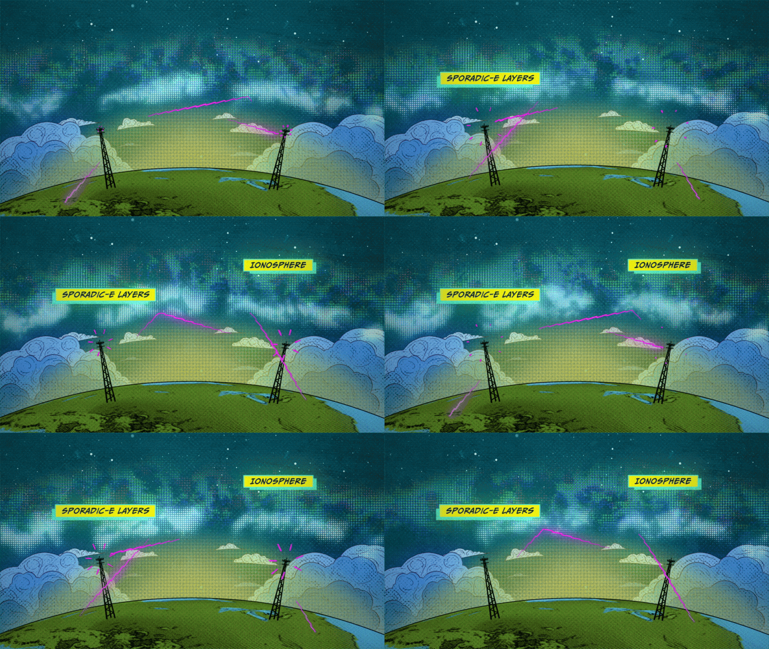
An animated illustration depicts Sporadic-E layers forming in the lower portions of the ionosphere, causing radio signals to reflect back to Earth before reaching higher layers of the ionosphere.
NASA’s Goddard Space Flight Center/Conceptual Image Lab
“Sporadic E layers are, in one sense, giant mirrors of radio frequency waves in the sky,” said Aroh Barjatya, the mission’s principal investigator and a professor of engineering physics at Embry-Riddle in Daytona Beach, Florida.
When a sporadic E layer forms, signals meant to travel out to space can ricochet back toward the ground. Air traffic controllers and marine radio users may pick up distant transmissions as though they were nearby, and radars scanning beyond the horizon can register so-called “ghosts,” or false targets. The effects reach everyday technology, too.
“The biggest source of error in the GPS in your phone, for example, is from the plasma in the ionosphere, and sporadic E layers can contribute to this uncertainty,” said Henry Valentine, the study’s lead author, who conducted the work at Embry-Riddle and is now a researcher at the U.S. Naval Research Laboratory.
Because sporadic E layers hover around 60 miles (100 kilometers) up—too high for weather balloons, too low for satellites — and form and dissipate unpredictably, they have long been the province of sounding rockets, which can be launched on short notice to catch one in the act. But a single rocket flies a single path, taking measurements only along a line. Barjatya likens the situation to viewing a scene through a crack in a wall. One can only observe what is happening along that narrow slit, missing out on the crucial context of whatever is occurring to the left or right of one’s view.
The SpEED Demon mission changed that. The mission was the first to deploy ejectable probes, called dropsondes, inside a sporadic E layer. Once inside, the rocket released four dropsondes that flew away from the main payload and from one another, each measuring the plasma along its own track and beaming its measurements back to ground stations. Together with the main payload, the probes sampled the layer in a total of five places at the same moment.
The SpEED Demon team poses with payload section during testing at NASA’s Wallops Flight Facility.
NASA Wallops/Berit Bland
“Now with multiple sensors, we’ve turned that crack into a picket fence,” Barjatya said.
The data revealed surprising complexity inside the sporadic E layer. Rather than a smooth, dense pancake of metallic particles, the layer that SpEED Demon flew through appeared uneven and structured, shaped by turbulent winds moving through the neutral air around it.
“A lot of times you think of sporadic E as this single sharp density layer, but what we saw in ours is it’s interacting with neutral wind and these swirling atmospheric turbulences,” Valentine said. “Rather than a flat pancake, it’s closer to a cinnamon roll.”
On the way down, the layer even split into two distinct peaks. The team found that shape was consistent with modulation by Kelvin-Helmholtz billows, the curling, wave-like instability that produces breaking-wave patterns in ordinary clouds. Because the flight was unable to measure the local winds and electric fields directly, the researchers are careful to call the billow explanation plausible rather than confirmed.
The SpEED Demon mission was designed as a technology demonstration — a test of whether the dropsonde technique would work at all. It did, and the team was quick to apply it again. Barjatya’s team used a similar multi-probe strategy to launch rockets into the paths of the October 2023 annular eclipse and April 2024 total solar eclipse, studying how the sudden darkness disturbed the upper atmosphere. In June 2025, they flew SpEED Demon’s most direct descendant, Sporadic-E ElectroDynamics, or SEED, into sporadic E layers from Kwajalein Atoll in the Marshall Islands, studying them at lower latitudes. Papers from those missions are in preparation.
A sounding rocket launch testing science instruments for future missions was successfully conducted at 9:16 p.m. EDT, Aug. 23, 2022, from NASA Wallops Flight Facility in Virginia.
NASA
After years of study, sporadic E layers are no longer as unpredictable as they once were. “They have a seasonality to them, with peak occurrence happening in the local summer,” Barjatya said.
Questions about how and when they form are increasingly fine-grained. The new deployable multi-point rocket sensor methodology, along with ground-based measurements, is likely to bring the picture even closer to completion. “The science community as a whole is now in its final stretches of fully understanding these giant radio frequency mirrors in the sky,” Barjatya said.
ByMiles Hatfield NASA’s Goddard Space Flight Center, Greenbelt, Md.
NASA awarded Blue Origin a contract Tuesday to develop the agency’s Mars Telecommunications Network, a next-generation communications system that will enable reliable, high-bandwidth communications and navigation services for current and future Mars missions.
The firm-fixed-price contract has a maximum potential value of approximately $700 million to deliver a high-performance Mars telecommunications orbiter to NASA no later than Dec. 31, 2028.
Blue Origin will design, develop, integrate, launch, and operate the network as a part of the agency’s broader space communications and navigation infrastructure. The architecture will consist of a high-performance telecommunications spacecraft orbiting Mars, transmitting science data, imagery, navigation information, and critical mission communications for spacecraft operating on and around the planet.
The award marks a milestone in NASA’s strategy to expand communications and navigation services beyond Earth and the Moon, establishing the foundation for sustained exploration of Mars in the coming decades.
Under the Artemis program, NASA is sending astronauts to explore the Moon and prepare for missions to Mars. Robotic missions will pave the way for human exploration of the Red Planet, and as these missions expand, demand for data will continue to increase. To meet this need, NASA is pursuing a purpose-built network capable of supporting a growing number of missions while providing greater capacity, reliability, and operational flexibility.
The selection follows NASA’s request for proposal issued in May. As the agency increasingly taps commercial partners for transportation and communications services in Earth orbit and to develop the Moon Base, the Mars Telecommunications Network initiative similarly seeks to harness private-sector capabilities while enabling NASA to focus on exploration and scientific discovery.
The network, managed by NASA’s Space Communications and Navigation program, is expected to be operational at Mars by 2030 and will support both current and future missions to the Red Planet, as NASA ventures deeper into space.
For more information about NASA’s space communications efforts, visit:
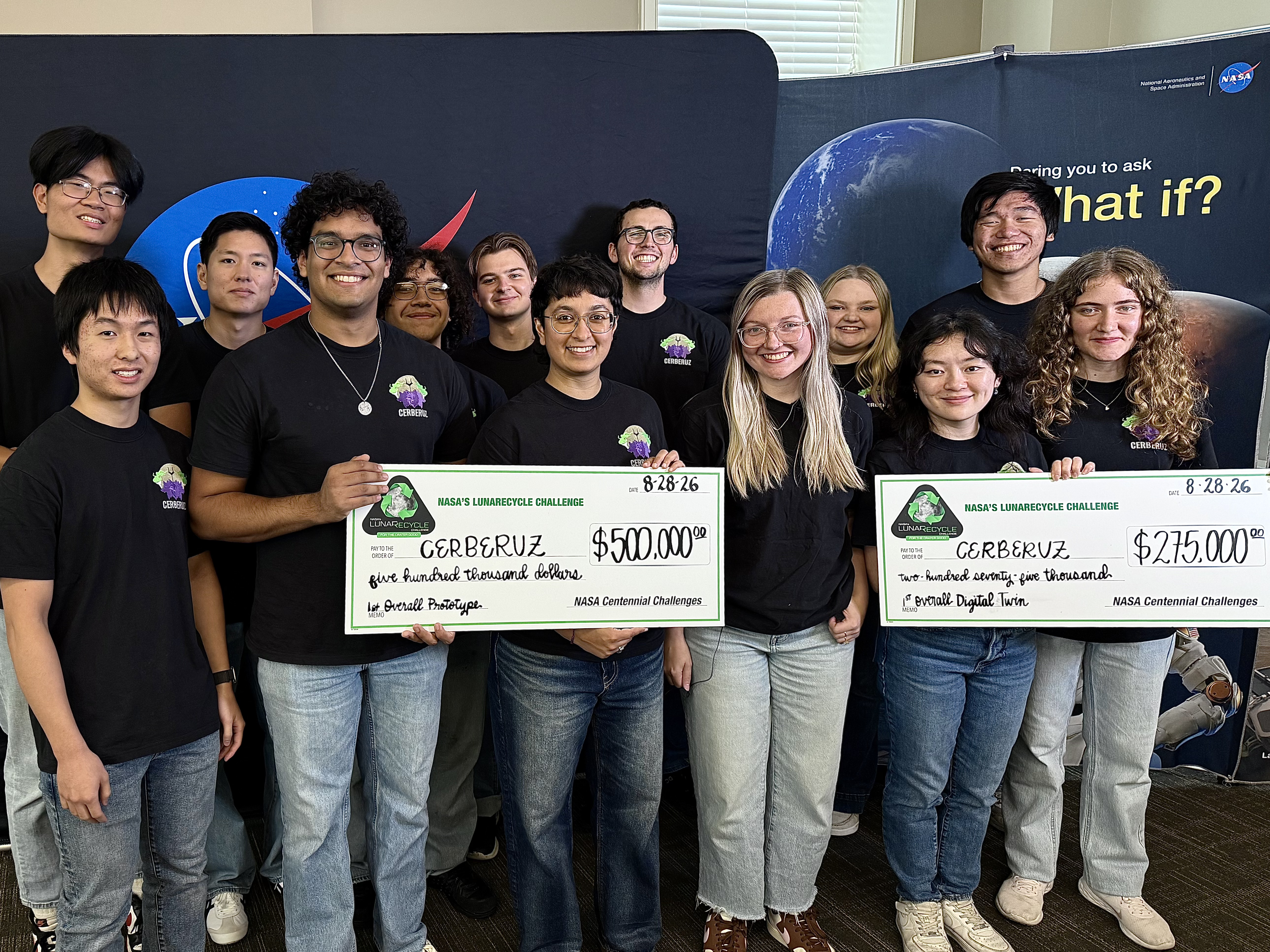
The Massachusetts Institute of Technology team won NASA’s LunaRecycle Challenge competition for their project, Composites for Extraterrestrial Recycling By Engineering the Reuse and Upcycling of Zotek (CERBERUZ).
Credit: NASA/Savannah Bullard
NASA named a team from the Massachusetts Institute of Technology (MIT) as the first prize winner for Phase 2 of the agency’s LunaRecycle Challenge, which focused on developing solutions for reducing waste during missions to the Moon or deep space by recycling common materials, like fabrics, plastics, foam, and metals.
The Composites for Extraterrestrial Recycling By Engineering the Reuse and Upcycling of Zotek (CERBERUZ) team, comprised of undergraduate, graduate, and doctoral students at MIT, received a total of $775,000 in awards.
The technology grinds mixed trash into a fine powder, repurposing materials such as Zotek foam as reinforcement rather than treating it as contamination that needs to be sorted out. The powder becomes feed for use as injection-mold finished parts or 3D-printing filament. The MIT team won in both the competition’s prototype development track and in the track focused on developing virtual models, known as “digital twins,” of recycling systems.
“The LunaRecycle Challenge finale is the culmination of two years of innovation spurred by this competition,” said Jennifer Edmunson, program manager for Centennial Challenges at NASA’s Marshall Space Flight Center in Huntsville, Alabama. “It’s incredible to see these technologies go from concept to prototype and digital twin demonstrations in that time. Driving rapid and creative innovation is what NASA challenges are all about.”
LunaRecycle is a $3 million, two-phase competition in partnership with The University of Alabama Lee J. Styslinger Jr. College of Engineering. Phase 2 of the competition required U.S. teams to submit a prototype, with an optional digital twin serving as a virtual model of it.
For Phase 2, 14 finalist teams from across the United States gathered at The University of Alabama’s Lee J. Styslinger Jr. College of Engineering, in Tuscaloosa, from Aug. 24 to Aug. 28 to demonstrate their technology prototypes. The digital twin models submitted by some teams were also presented alongside their respective prototypes.
The competitors’ backgrounds ranged from university students and faculty to entrepreneurs and space technology enthusiasts. Teams were encouraged to envision solutions that not only addressed recycling in deep space, but that also could have applications on Earth.
Along with the first prize winner, nine teams received prizes:
Prototype track winners:
Second place overall ($225,000): Terasynth from Orlando, Fla. with Lunar Re-Forge System
Most Innovative ($50,000): RECLAIM from Penn State University with the Resource Extraction and Conversion from Lunar Anthropogenic Inputs with Microwaves (RECLAIM) system
Highest Mass Efficiency ($50,000): Cislune from Rosemead, Calif. with the Carbon Recovery and Feedstock Transformation for Extraterrestrial Reuse (CRAFTER) system
Most Trash Types Recycled ($50,000): Team Lovegrove from Bob Jones University in Greenville, S.C. with LunaBrix
Additional digital twin track winners:
Second place overall ($125,000): Moon Made from Boulder, Co. with Fiber Forge
Most Innovative ($25,000): RECLAIM from Penn State University with the RECLAIM system
Best Visualization ($25,000): Waste Parrot Technologies from New York, N.Y.
People’s choice winner ($25,000):
Terasynth from Orlando, Fla. with Lunar Re-Forge System
“This competition highlights how collaborations can lead to incredible solutions,” said Chris Frangione, who manages the LunaRecycle Challenge in support of NASA Centennial Challenges contracted through Amentum Space Exploration Division. “Between the solver teams, The University of Alabama, and NASA, this finale showcases what can be achieved when we bring together resources and great ideas towards a common goal.”
The Phase 2 awards follow the success of the competition’s Phase 1, which received record-breaking interest from the global innovator community with more than 1,200 registrations – more than any competition in the 20-year history of NASA Centennial Challenges. For Phase 1, which concluded in 2025, participants from around the world could submit designs in either or both of the prototype or digital twin tracks. A panel of 50 judges evaluated nearly 200 Phase 1 submissions, selecting 17 teams representing five countries and nine U.S. states as winners. Phase 2 entries were required to be unrelated to Phase 1.
The LunaRecycle Challenge is managed at NASA’s Marshall Space Flight Center by Centennial Challenges, part of the Prizes, Challenges, and Crowdsourcing program within NASA’s Research and Technology Mission Directorate. NASA’s Centennial Challenges have a legacy of more than 20 years engaging the public to solve complex problems that benefit NASA’s broader initiatives. Past challenges have spurred advances in robotics, additive manufacturing, power and energy, textiles, chemistry, and biology.
LunaRecycle is also supported by subject matter experts at NASA’s Kennedy Space Center in Florida, NASA’s Ames Research Center in California’s Silicon Valley, and NASA’s Langley Research Center, in Hampton, Virginia.
NASA Begins Moon Mission Plume-Surface Interaction Tests
A run of the plume-surface interaction testing with the ethane nozzle firing into the simulated lunar dirt.
Credits: NASA
EDITOR’S NOTE: This story, originally published in December, was revised Aug. 26, 2026 with an update on a new phase of testing, including video from a recent test run and new images.
To help NASA and commercial partners better understand the science of lunar landings, specifically the hazards that may occur when a lander’s engine plumes blast away at lunar dust, soil, and rocks, a team at NASA’s Langley Research Center in Hampton, Virginia, has initiated a series of plume-surface interaction tests inside a massive 60-foot spherical vacuum chamber.
As NASA works to return humans to the Moon starting with Artemis IV in 2028 and develop a Moon Base, the tests will provide a trove of data for researchers to use to improve predictive models and influence the design of space hardware.
“This plume-surface interaction ground test is the most complex test of its kind to be undertaken in a vacuum chamber,” said Ashley Korzun, testing lead at NASA Langley. “If I’m in a spacecraft and I’m going to move all that regolith while landing, some of that’s going to hit my lander. Some of it’s going to go out toward other things — payloads, science experiments, eventually rovers and other assets. Understanding those physics is pivotal to ensuring crew safety and mission success.”
The campaign involves multiple NASA centers, academic institutions, and commercial entities both small and large.
Korzun’ s team will test two types of propulsion systems in the vacuum sphere. For the first round of tests, they are using an ethane plume simulation system designed by NASA’s Stennis Space Center near Bay St. Louis, Mississippi, and built and operated by Purdue University. The ethane system generates a maximum of about 100 pounds of thrust — imagine the force necessary to lift or support a 100-pound person. It heats up but doesn’t burn.
The team recently began firing the system into a roughly six-and-a-half-foot diameter, one-foot-deep bin of simulated lunar regolith, called Black Point-1, that has jagged, cohesive properties similar to actual lunar regolith.
A number of different instruments, including a version of the Stereo Cameras for Lunar Plume Surface Studies system that imaged the plume-surface interaction when Firefly’s Blue Ghost Mission-1 landed on the Moon in 2025, are capturing data and imagery from the tests, which will only last about six seconds each. The instruments are measuring things such as crater formation, angle and height of the ejecta sheet, spatial distribution of solid ejecta, and the speed of the regolith particles as they get blasted out of the bin.
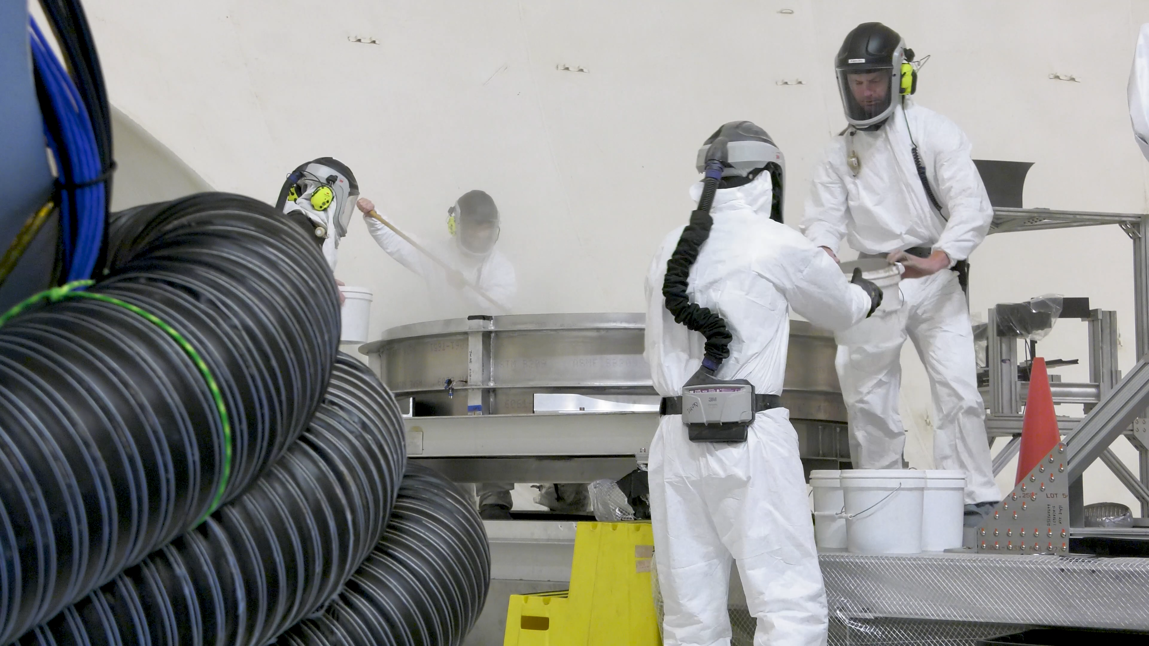
A crew loads simulated lunar dirt into the test bin in the 60′ vacuum sphere.
NASA/Rob Lorkiewicz
Later this year, a second round of tests will involve a 14-inch, 3D-printed hybrid rocket motor developed at Utah State University in Logan, Utah, and tested at NASA’s Marshall Space Flight Center in Huntsville, Alabama. It produces around 35 pounds of thrust, igniting both solid propellant and a stream of gaseous oxygen to create a hot, powerful stream of rocket exhaust, simulating a real rocket engine but at smaller scale for this test series. Researchers will test both propulsion systems at various heights.
“It gives us a huge range of test conditions,” Korzun said, “to be able to talk about spacecraft of all different kinds going to the Moon, and for us to understand what they’re going to do as they land or try to take back off from the surface.”
Korzun sees this test campaign as more than a one-shot, Moon-specific thing. The entire operation is modular by design and also can prepare NASA for missions to Mars. The lunar regolith simulant can be replaced with a Mars simulant that’s more like sand. Pieces of hardware and instrumentation can be unbolted and replaced to represent future Mars landers. Rather than take the vacuum sphere down to really low pressure like on the Moon, it can be adjusted to a pressure that simulates the atmosphere on the Red Planet.
“Mars has always been in our road maps,” Korzun said.
But for now, the Moon looms large.
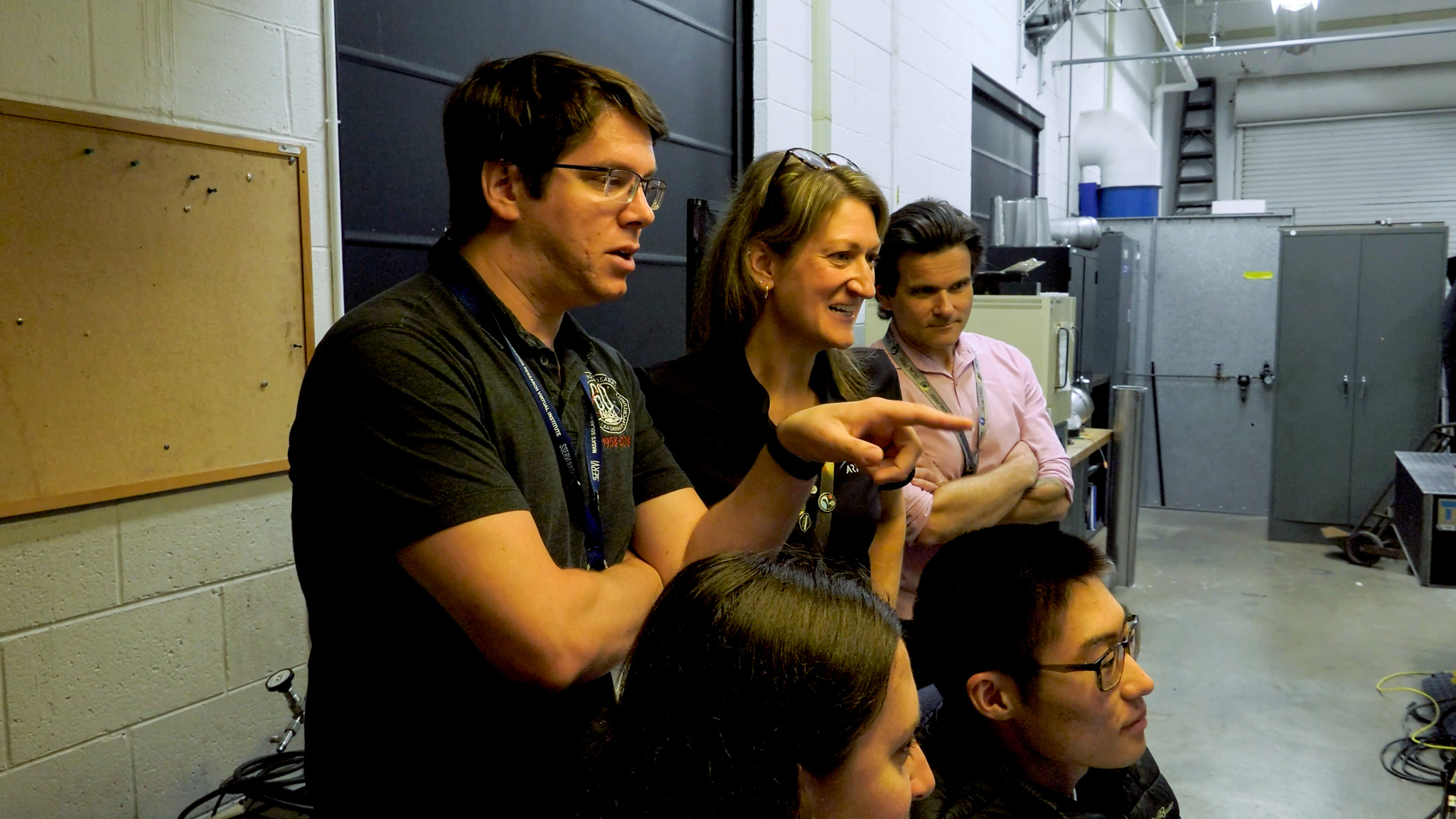
Clockwise from left: Wesley Chambers, deputy principal investigator for the PSI tests from Marshall’s Space Flight Center in Huntsville, Alabama; Ashley Korzun, test lead and principal investigator; Dave Lehotay, project manager; and Tylor Takahashi and Olivia Tyrrell, both from the SCALPSS instrument team, watch test footage in the control room.
NASA/Rob Lorkiewicz
“This test campaign is one of the most flight-relevant and highly instrumented plume-surface interaction test series NASA has ever conducted,” said Daniel Stubbs, an engineer with the Human Landing Systems plume and aero environments team at NASA Marshall. “The data from these tests at NASA Langley will be critical in developing and validating models to predict the effects of plume-surface interaction for landing on the Moon and even Mars, ensuring mission success for the human landing systems and the safety of our astronauts.”
Through the Artemis program, NASA will send astronauts on increasingly complex missions to explore the Moon for scientific discovery, economic benefits, establish an enduring human presence on the lunar surface, and to build on our foundation for the first crewed missions to Mars.
To help NASA and commercial partners better understand the science of lunar landings, specifically the hazards that may occur when a lander’s engine plumes b...
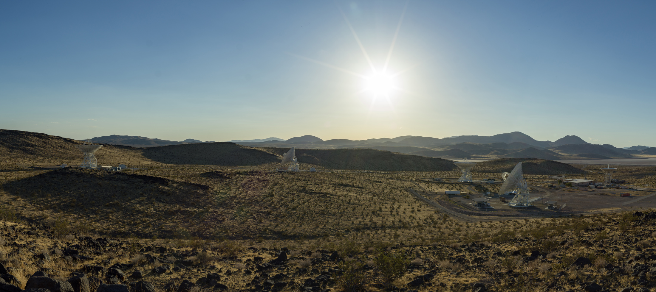
Antennas soak in the summer Sun in August 2026 at the Deep Space Network’s Goldstone complex near Barstow, California, including the recently completed Deep Space Station 23 (shown in the foreground, to the right).
NASA/JPL-Caltech
NASA’s Deep Space Network facility in California is marking the addition of a brand new 34-meter-wide (114-foot-wide) radio frequency antenna to the agency’s deep space communications and navigation system. The network uses giant dish antennas located at three global facilities to support more than 40 spacecraft exploring the solar system and interstellar space.
The new Deep Space Station 23 (DSS-23) is located at the Goldstone Deep Space Communications Complex, near Barstow, and is managed by NASA’s Jet Propulsion Laboratory in Southern California.
NASA leadership and personnel as well as dignitaries gathered at the complete DSS-23 antenna for a ceremonial ribbon cutting. It’s the latest to be added as part of the Deep Space Network’s Aperture Enhancement Project, which began in 2009 to upgrade and expand the network by adding six new 34-meter multifrequency beam-waveguide antennas. These versatile dishes can enhance many missions operating over different radio frequencies.
“By expanding the Deep Space Network, we are strengthening the communications foundation NASA needs for the bold missions ahead — from exploring more of the Moon than ever before to peering deeper into the solar system,” said James Kenyon, associate administrator of the Research and Technology Mission Directorate at NASA Headquarters in Washington. “This new antenna will help us deliver on our national goals for space exploration and push beyond the limits of what once seemed impossible.”
After completing a testing campaign from May through July to demonstrate its capabilities, the new DSS-23 began operations on Aug. 3, tracking NASA’s Chandra X-ray Observatory. Since then, it has been communicating with dozens of missions such as NASA’s Mars Reconnaissance Orbiter, Psyche, Juno, Voyager 1, and other robotic spacecraft in deep space.
Long shadows are cast by the recently completed Deep Space Station 23 at the Deep Space Network’s Goldstone complex near Barstow, California. A multifrequency beam waveguide antenna, DSS-23 will boost the DSN’s capacity and enhance NASA’s deep space communications capabilities for decades to come.
NASA/JPL-Caltech
NASA, Jet Propulsion Laboratory, and Deep Space Network leadership pose in front of the recently completed Deep Space Station 23 (DSS-23) antenna at the Deep Space Network’s Goldstone complex near Barstow, California, on Aug. 25, 2026..
NASA/JPL-Caltech
“The addition of this next-generation antenna brings us closer to a completely modernized network that embraces advanced technology to ensure NASA’s leadership in deep space communications,” said Dave Gallagher, director of JPL. “After over 60 years of continuous operations supporting consequential missions, these upgrades prime the network for a new era of exploration. The teams that designed, planned, and built DSS-23 should be proud.”
Enhanced capabilities
Construction of DSS-23 began in February 2020. After the 133-ton metal reflector framework was placed and bolted atop the antenna’s pedestal in December 2024, engineers installed the panels to the framework that reflect radio frequency signals transmitted to and received from spacecraft. Then came the careful process of calibrating the antenna so it can work in concert with the rest of the network.
It is the fifth antenna at Goldstone (joining three 34-meter antennas and one 70-meter, or 230-foot, antenna) and the fifth enhancement project antenna to join the network, which includes antennas at the DSN’s Goldstone, Madrid, and Canberra, Australia, complexes. Multifrequency beam waveguide antennas direct signals down to a stable, climate-controlled underground room, rather than housing heavy, sensitive electronic equipment on the moving antenna dish. In addition to offering versatility, this design allows easy access for maintenance and upgrades to the system.
“The biggest challenge wasn’t actually constructing the antenna. It was transforming a complex collection of mechanical, electrical, software, radio frequency, and infrastructure systems into a single, mission-ready asset,” said Germaine Aziz, manager of the Deep Space Network Aperture Enhancement Project at JPL. “Every subsystem must be integrated, calibrated, and verified to operate with extraordinary precision and reliability before it can support NASA’s deep space missions.”
The enhancement project will be complete when a sixth enhancement-project antenna, Deep Space Station 33, comes online at the Canberra facility in 2029, bringing the total number of 34-meter antennas across the network to 13. The 34-meter antennas can be arrayed (combined and operated together) to provide an equivalent communications backup for each facility’s single 70-meter antenna, which, after more than 50 years of near-continuous operation, are getting increasingly costly to maintain and repair.
Managed by Caltech for NASA, JPL manages the agency’s Deep Space Network with the oversight of NASA’s SCaN (Space Communications and Navigation) Program within NASA’s Research and Technology Mission Directorate. More than 100 NASA and non-NASA missions rely on the Deep Space Network and Near Space Network. They include missions that support astronauts aboard the International Space Station and future Artemis missions, monitoring Earth, exploring the Moon, and exploring the solar system and beyond.
For more information about the Deep Space Network, visit:
NASA will announce the winners of the final phase of its LunaRecycle Challenge on Friday, Aug. 28, at The University of Alabama (UA) Lee Styslinger College of Engineering in Tuscaloosa, Alabama. Launched in 2024, the challenge incentivizes the invention of new recycling systems that could support non-metabolic waste management efforts for future lunar missions.
Media and the public are invited to the challenge’s Technology Showcase and Winners Announcement, where up to 14 finalist teams will showcase their solutions and hear from NASA and UA leadership about the future of lunar innovation. Opening remarks will begin at 8:30 a.m. CDT on Aug. 28, in Room 1026 of H.M. Comer Hall on the UA campus.
Media interested in covering the event should confirm their attendance with the NASA Marshall newsroom by 3 p.m., Wednesday, Aug. 27, at: joel.w.wallace@nasa.gov.
The LunaRecycle Challenge is a $3 million, two-phase competition focused on the design and development of recycling solutions that can reduce non-metabolic waste and improve the sustainability of longer-term lunar missions. In the Final Round of Phase 2, invited teams were tasked with refining their prototype and digital twin concepts in preparation for live testing at McAbee Construction in Tuscaloosa earlier this month.
After this event, up to 11 teams will receive a portion of the $1.325 million prize purse from NASA for their prototype and digital twin solutions. The top two prototypes will earn $500,00 and $225,000, while top two digital twins will receive $275,000 and $125,000. Up to six Technical Achievement Prizes will be awarded to teams who excel in categories determined by the judging panel during final deliberations. Additionally, a $25,000 People’s Choice Award will be presented to the team who receives the most votes from the public and stakeholders throughout the Technology Showcase.
Winners will be announced live during the Technology Showcase closing ceremony, which begins at 12 p.m.
The LunaRecycle Challenge is managed at NASA’s Marshall Space Flight Center by Centennial Challenges, part of the Prizes, Challenges, and Crowdsourcing Program within NASA’s Research and Technology Mission Directorate. NASA’s Centennial Challenges have a legacy of more than 20 years engaging the public to solve complex problems that benefit NASA’s broader initiatives. Past challenges have spurred advances in robotics, additive manufacturing, power and energy, textiles, chemistry, and biology.
Phase 1 of the competition received record-breaking interest from the global innovator community. The challenge received more than 1,200 registrations – more than any competition in the 20-year history of Centennial Challenges – and a panel of 50 judges evaluated nearly 200 submissions. Seventeen teams were selected as Phase 1 winners, representing five countries and nine U.S. states, announced via livestream on NASA Marshall’s YouTube channel.
The LunaRecycle Challenge also is supported by recycling subject matter experts at NASA’s Kennedy Space Center in Florida and NASA’s Ames Research Center in California’s Silicon Valley. The University of Alabama Lee J. Styslinger Jr. College of Engineering executes the challenge in partnership with NASA.
To learn more about the LunaRecycle Challenge visit:
Starstruck: NASA Research Shows How Sun’s Ancient History Shaped Earth
At the center of our solar system, the Sun influences every planet that orbits it. In two recent NASA-funded studies, scientists uncovered how ancient events in the Sun’s history may have helped create Earth’s unique climate and driven previously unexplained climatic shifts.
In new research, scientists at NASA’s SHIELD (Solar Wind with Hydrogen Ion charge Exchange and Large-Scale Dynamics) center — one of NASA’s DRIVE (Diversify, Realize, Integrate, Venture, Educate) Science Centers — trace the trajectory of the heliosphere, the massive bubble created by our Sun that envelops our solar system, as it moved through our galaxy and influenced Earth’s climate along the way. In another paper, a NASA scientist and coauthors investigate how the younger, dimmer Sun managed to heat Earth by seeding the production of potent greenhouse gases.
A Sun on the move
Over the last tens of millions of years, Earth’s climate has undergone significant shifts, including notable ice ages in which the global average temperature temporarily dropped by several degrees. During these periods, more frequent climate swings led Earth to warm and cool. To explain these periods of warming and cooling, scientists looked to factors internal to Earth, including orbital changes, greenhouse gases, and ice. But new research suggests changes to the Sun’s environment may be key to understanding Earth’s temperature swings.
Just as our planet is encased by an atmosphere, so our entire solar system is encased inside a kind of “atmosphere” created by the Sun. This protective bubble, known as the heliosphere, is formed by a continuous solar wind of charged particles streaming out from the Sun in all directions.
This conceptual animation begins with a view of the Milky Way Galaxy. As we zoom in, we travel to the Local Interstellar Cloud, and then to the heliosphere, the protective bubble that surrounds our solar system. The heliosphere is formed by a continuous stream of charged particles from the Sun, called the solar wind.
NASA’s Goddard Space Flight Center Conceptual Image Lab
Our heliosphere orbits around the center of our galaxy, the Milky Way. Throughout the Sun’s 4.6-billion-year existence, our heliosphere has traversed various regions within our galaxy. In a paper published on Aug. 21 in Annual Review of Astronomy and Astrophysics, researchers at NASA’s SHIELD used computer modeling to reverse-engineer the path of the heliosphere through our galaxy, revealing that the environments it passed through may have triggered changes on Earth.
Merav Opher, SHIELD’s principal investigator at Boston University, and her team ran simulations that showed the Sun has encountered frigid expanses of gas and dust at least three different times in the past few million years. In these instances, massive interstellar “cold clouds” pushed against the heliosphere to such an extent that it shrank to smaller than Earth’s orbit, stranding our planet outside the Sun’s protective shield.
These exposures — approximately 2 to 3 million years, 6 to 7 million years, and 13 to 14 million years ago — would have exposed Earth’s atmosphere to totally different surroundings. The simulation results match geologic evidence: Elements prevalent in interstellar dust appear in deep-sea sediment core samples, Antarctic snow, and lunar samples during these timelines.
This animated illustration shows Earth and the Sun protected by the heliosphere, the massive bubble created by our Sun. As our solar system traverses through the galaxy, encounters with massive interstellar “cold clouds” pushed against the heliosphere and caused the heliosphere to shrink past Earth, exposing the planet to cosmic radiation and elements from interstellar space.
NASA’s SHIELD DRIVE Science Center/Merav Opher/Harvard Radcliffe Institute
These heliosphere collapse events may also explain ancient climatic patterns on Earth. In the simulations, when Earth’s atmosphere was exposed to a cold, dense galactic hydrogen cloud, it increased water vapor content and shifted upper-atmospheric dynamics, ultimately altering the conditions at the surface. In summary, our heliosphere’s trips through colder regions in our galaxy may be a key factor in driving some of Earth’s ancient changes in climate, including possible ice ages.
Next frontier in studying heliophysics
The SHIELD center is one of several that NASA funds to unlock the next generation of heliospheric research. As a DRIVE Science Center, SHIELD builds a team of researchers with differing expertise, approaches, and opinions to develop a model, or “digital twin,” of the heliosphere that helps reveal how the heliosphere interacts with its surroundings, including dense interstellar clouds. Understanding our unique, habitable solar system will help unravel the mysteries of life’s evolution on Earth and potentially uncover other habitable star systems.
Young Sun
In another paper, Vladimir Airapetian, a scientist at NASA’s Goddard Space Flight Center in Greenbelt, Maryland, focuses on a long-standing mystery of how the ancient Sun warmed early Earth enough to sustain life. Three billion years ago, the young Sun was 70% as bright as it is today. Under these dimmer conditions, Earth should have been frozen solid. Yet geological evidence shows stable liquid water already existed long before that. This puzzle — a balmy Earth under a cooler, dimmer Sun — is known as the Faint Young Sun paradox.
One clue to resolving the paradox comes from young Sun-like stars elsewhere in the galaxy. These “toddler” stars are prone to throwing fits. Specifically, data from NASA’s retired Kepler space telescope shows that young Sun-like stars regularly erupt with massive superflares, flinging high-energy particles in all directions on a daily basis. If our young Sun was like these other stars, Airapetian proposes, the barrage of high-energy solar particles could have triggered chemical reactions that were key to warming early Earth.
Airapetian’s team simulated early Earth’s atmosphere in a sealed chamber, mixing molecular nitrogen, ammonia, carbon dioxide, and carbon monoxide. They then fired protons into the mixture, simulating the onslaught of particles from superflares. This proton bombardment triggered several changes including the production of nitrous oxide, a greenhouse gas 300 times more potent than carbon dioxide. The research was published in Astrophysical Journal Letters.
This nitrous oxide could help Earth hold onto heat. But not all the nitrous oxide would last. The young Sun’s intense ultraviolet radiation would break some of it down, splitting the molecule back into nitrogen and oxygen. But even if only 10% of the nitrous observed in the experiment survived, Airapetian’s team’s computer simulations confirmed, it would still warm Earth’s equatorial regions to about 41 degrees Fahrenheit (5 degrees Celsius), above water’s freezing point. This smaller amount of nitrous could even accelerate prebiotic synthesis: just-above-freezing temperatures have been found to be more efficient for building complex chains of amino acids than warmer temperatures.
Unearthing secrets of our star-planet system
Together, these two studies show that the Sun can lead to surprising implications for Earth. While our planet stands alone in many ways, it was formed and has always existed as part of a star-planet system. Understanding that unique relationship promises new insights about both Earth and the star that sustains it.
Preparations for Next Moonwalk Simulations Underway (and Underwater)
NASA has selected four university teams to help the agency transform the future of aviation through projects ranging from high-supersonic propulsion systems to low-noise routes for small aircraft flying through cities.
The agency made awards through its University Leadership Initiative, which offers student teams the opportunity to contribute to real-world flight research that advances NASA’s goals in aeronautics.
This year’s awardees are pursuing projects that align with NASA strategic objectives, including innovation in commercial high-speed aircraft, the development of new tools that can lead to transformational aviation breakthroughs, safer and more efficient air traffic management, and the integration of new air transportation options into the national airspace.
“With these four new awards, the University Innovation project is leaning in on NASA’s aeronautics mission priorities,” said Andrew Provenza, project manager, NASA’s Glenn Research Center in Cleveland. “These teams will research new propulsion concepts for supersonic flight, novel engineering methods that can revolutionize aerospace system design and certification, and learning-enabled avionics for new advanced and urban air mobility flight vehicle platforms, which could enhance air traffic control modernization.”
The awards represent the ninth round of NASA University Leadership Initiative funding.
Totaling about $30 million, NASA’s awards will provide multiyear support for awardee universities to build their teams and conduct research. The initiative provides hands-on experiences for students, developing the U.S. aeronautics research workforce while also producing findings that will help drive aviation forward.
University Leadership Initiative awards go to teams comprised of graduate and undergraduate students and led by faculty members. Recipients form academic partnerships with other universities and community colleges, as well as industry. Experts from NASA, the Federal Aviation Administration, and other organizations provide support and guidance.
The awardees are:
University of Minnesota
Adaptive Supersonic Combined Cycle Engine for Next-generation Transportation
Led by Terrence Meyer, the project will work over four years to develop a fuel-flexible propulsion system that uses a traditional jet turbofan during takeoff and subsonic flight, but would transition to a new type of ramjet engine for supersonic flight. In ramjet mode, the system would cruise at Mach 4, or more than 3,000 mph. The project aims to enable efficient, faster-than-sound flight, including flight at high-supersonic speeds.
Stanford University
Safety Across Lifecycle of Learning-Enabled Avionics Systems: Safety Data Flywheel
Led by Somil Bansal, this four-year project aims to develop an avionics system to control an aircraft’s communications, navigation, and other electronics that incorporates machine learning. The system would take an approach that ensures safety is continuously reinforced throughout its operations. This research could help create a framework for the aviation sector to safely integrate artificial intelligence-enabled avionics into the national airspace.
Stanford University
Noise-Optimal Trajectory Planning for Urban Air Mobility Operations, Including Ambient Noise
Led by Juan Alonso, the center created through this award will work over four years to develop a high-fidelity simulation framework focused on developing low-noise flight paths in urban environments for future small aircraft. Developers are envisioning urban air mobility aircraft as ways to move people and cargo over populated areas. This center would integrate realistic models of how sound travels in cities to enable vehicle flight paths that would reduce community noise exposure from new air traffic.
Virginia Tech
Certification Driven Aircraft Design Under Uncertainty
Led by Darshan Sarojini, this three-year project proposes to transform next-generation aircraft design while integrating powerful new computer modeling tools: model-based systems engineering, multidisciplinary design, analysis and optimization, and high-dimensional uncertainty quantification. The goal is safe, faster, and more efficient modeling that results in fewer costly redesigns later in the aircraft development cycle.
For more than 10 years, NASA’s University Leadership Initiative has fostered bold ideas, collaborative research, and team-led solutions. The initiative is part of NASA’s Research and Technology Mission Directorate.
Preparations for Next Moonwalk Simulations Underway (and Underwater)
The Orbital Clarity Challenge — the sixth in the NASA TechLeap Prize series — is a collaborative effort between NASA’s Heliophysics Division, Flight Opportunities program, and Center of Excellence for Collaborative Innovation. The Heliophysics Division studies space weather, including how it heats and expands Earth’s outer atmosphere during intense solar activity, creating orbital drag through atmospheric density changes. The challenge calls for low-cost methods of measuring thermospheric density, pressure, or drag in low Earth orbit. NASA is seeking approaches that are inexpensive and scalable enough to be produced in quantity and flown as hosted payloads across the commercial fleet. The challenge will unfold across three phases, advancing up to four winners’ concepts to a flight-ready solution within 12 months. At the conclusion of the challenge, NASA intends to offer each winning team a test flight at no cost.
Award: Up to four winners may receive up to $500,000 in prizes across three phases
Preparations for Next Moonwalk Simulations Underway (and Underwater)
Credit: National Institute of Aerospace
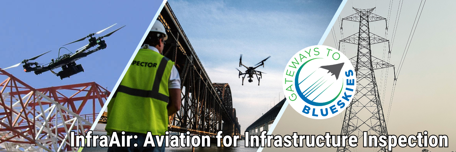
NASA’s next Gateways to Blue Skies competition invites collegiate teams to imagine innovative new ways aircraft could inspect land-based infrastructure, such as bridges and tunnels, to improve safety, reliability, and costs by 2035 or sooner.
Infrastructure is the foundation of the nation’s strong economy, global competitiveness, and daily quality of life. When that infrastructure is damaged or in disrepair, it restricts the movement of people, goods, and critical resources like water and energy. Inspections are important throughout the lifetime of infrastructure projects, but they often come with challenges.
Structures such as tunnels, bridges, highways, railways, and electric grids can be massive in size and difficult to reach. They can require disruptive shutdowns to access, or force workers to navigate extreme heights, confined spaces, and hazardous environments. As infrastructure ages and expands, there are opportunities to use innovative airborne platforms to improve current inspection practices.
“The demands for creative solutions like airborne platforms to improve the infrastructure sector are increasing exponentially,” said Steven Holz, Gateways to Blue Skies competition lead, NASA’s Langley Research Center in Hampton, Virginia. “The time is ripe for innovative students to transform how we work with our critical infrastructure, and this competition gives talented students the opportunity to do so.”
Sponsored by NASA’s University Innovation Project, the 2027 Gateways to Blue Skies competition encourages multidisciplinary teams of college students to conceptualize innovations in the world of aviation. Each year, the competition selects a new theme based on a complex challenge facing the Nation. It aims to engage as many students as possible from all backgrounds, majors, and collegiate levels.
The competition is open to teams of two to six students and divided into two phases. In Phase 1, teams will submit a proposal and an accompanying two-minute video, which will be judged by NASA and industry experts. Up to eight finalist teams will each receive a $9,000 prize and advance to Phase 2, where they will present their updated work to a panel of NASA and industry experts at a forum in May 2027. Winners will be offered the opportunity to intern with NASA Aeronautics in the academic year following the forum.
Teams interested in participating in the competition can review guidelines and eligibility requirements posted on the competition website. Teams are encouraged to submit a non-binding Notice of Intent by Monday, Oct. 12, via the website to stay apprised of competition news. Proposal and video submissions are due Feb. 22, 2027. The Gateway to Blue Skies Competition is run by the Aeronautics Division in NASA’s Research and Technology Mission Directorate. NASA’s Center of Excellence for Collaborative Innovation, part of the Prizes, Challenges, and Crowdsourcing Program within the Research and Technology Mission Directorate, manages the challenge contract. The National Institute of Aerospace administers the challenge on behalf of NASA.
NASA Challenge Tests Wheel Designs for Moon Base Mobility
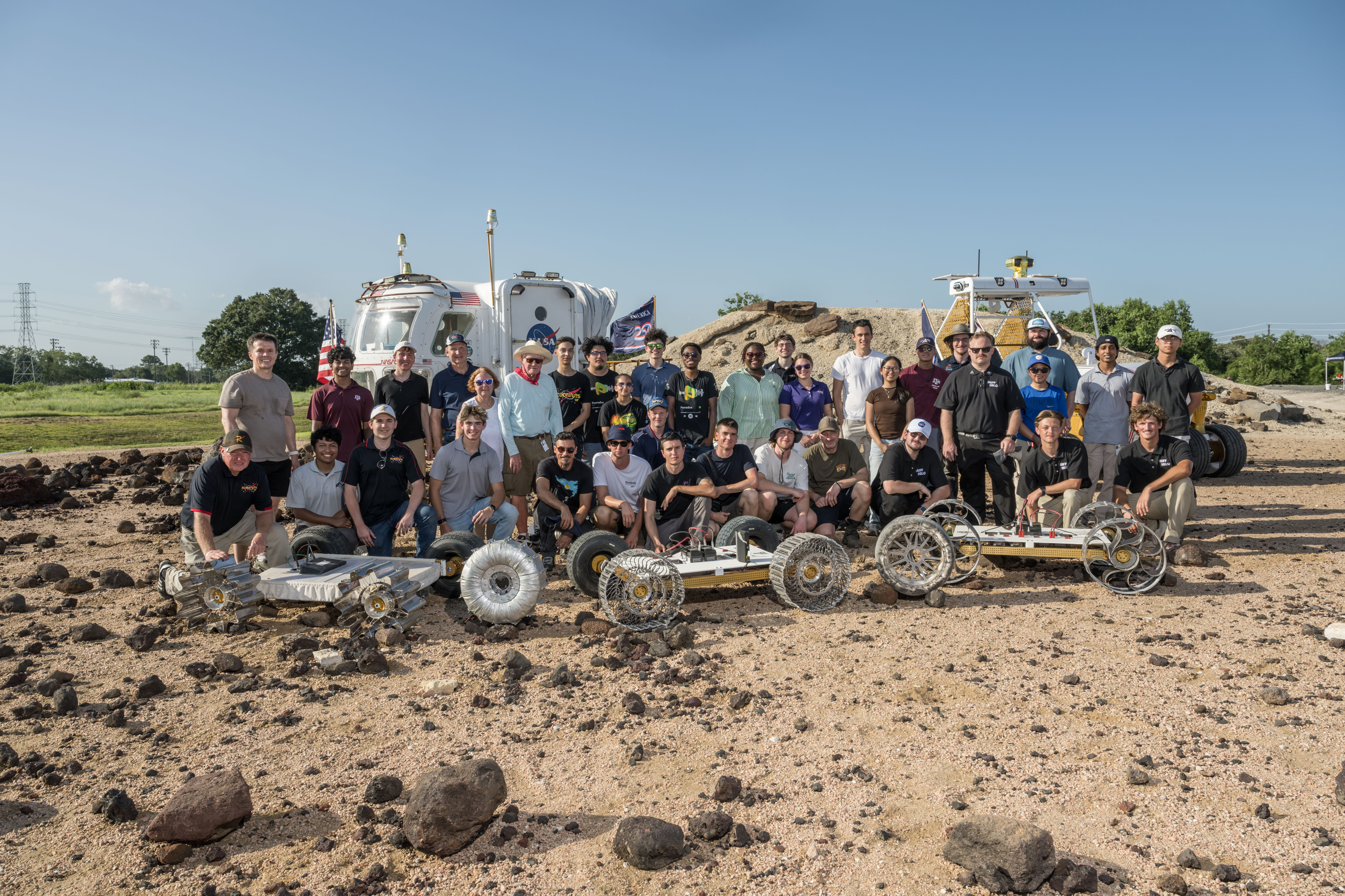
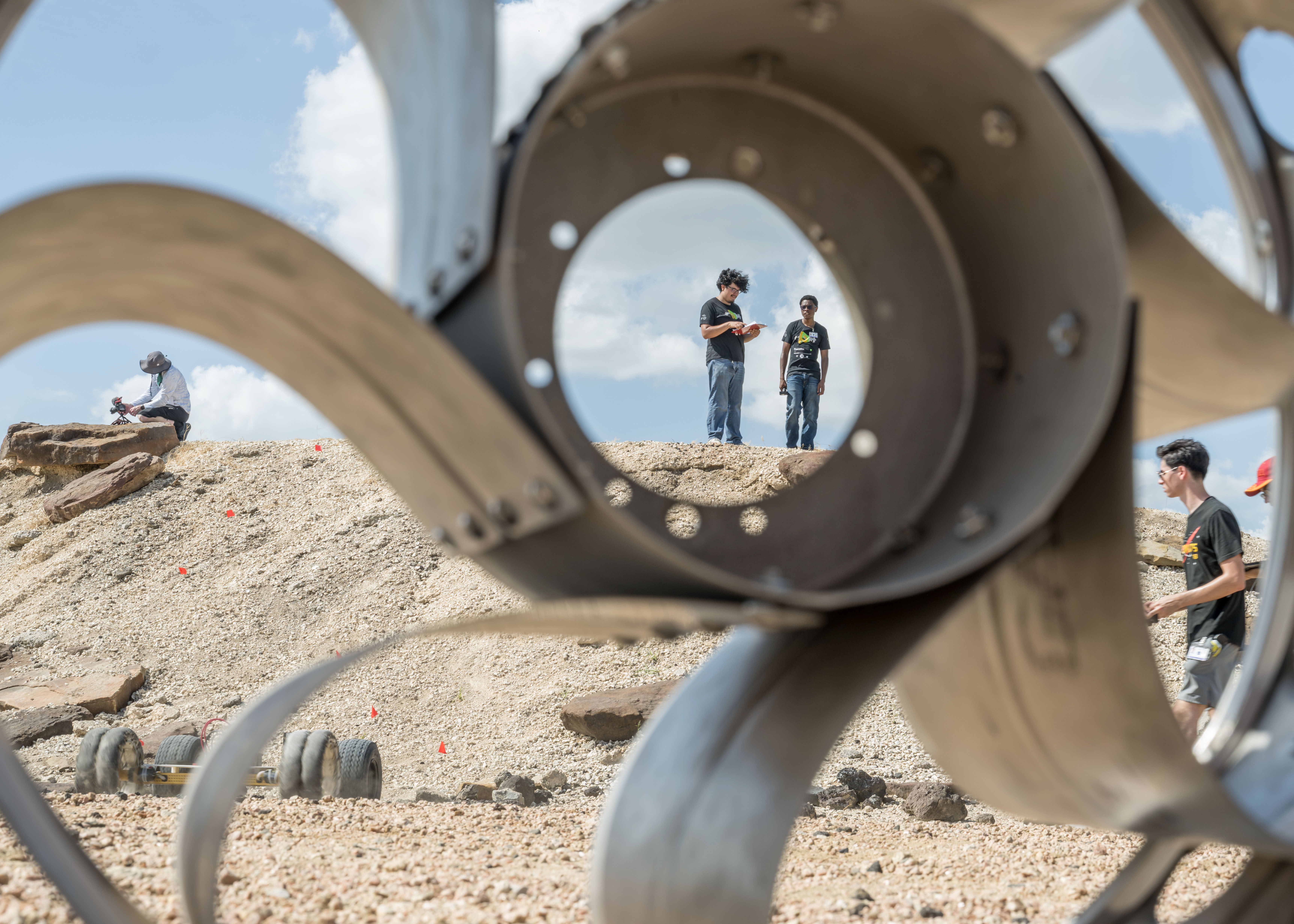
NASA engineers, NASA Robotics Academy students, and teams from the Rock and Roll with NASA Challenge pose with the wheel prototypes at NASA’s Johnson Space Center Rock Yard in Houston on July 31, 2026.
Credits: NASA/Luna Posadas Nava
NASA engineers, NASA Robotics Academy students, and teams from the Rock and Roll with NASA Challenge pose with the wheel prototypes at NASA’s Johnson Space Center Rock Yard in Houston on July 31, 2026.
NASA/Luna Posadas Nava
As NASA prepares to establish the Moon Base, advancing surface mobility will be key to helping crews and robotic systems travel farther across the lunar surface.
To help advance that capability, the Rock and Roll with NASA Challenge invited public innovators to design and build next-generation lunar rover wheels.
Five teams from 128 submissions and 49 countries advanced to the final phase of the competition, where they tested their prototypes on July 31 at NASA’s Johnson Space Center in Houston.
The Huff Helo lunar wheel prototype is tested at Johnson Space Center’s Rock Yard.
NASA/Luna Posadas Nava
The challenge sought lightweight, durable, and scalable wheels that could support longer-duration lunar surface operations. The designs also needed to be compliant enough to absorb impacts, maintain traction at higher speeds, and withstand the harsh lunar environment.
“Every additional kilometer a rover can reliably travel will expand how far we can explore, what science we can achieve, and what infrastructure we can build,” said Ed Herrera, robotics engineer at Johnson and co-leader of the challenge project.
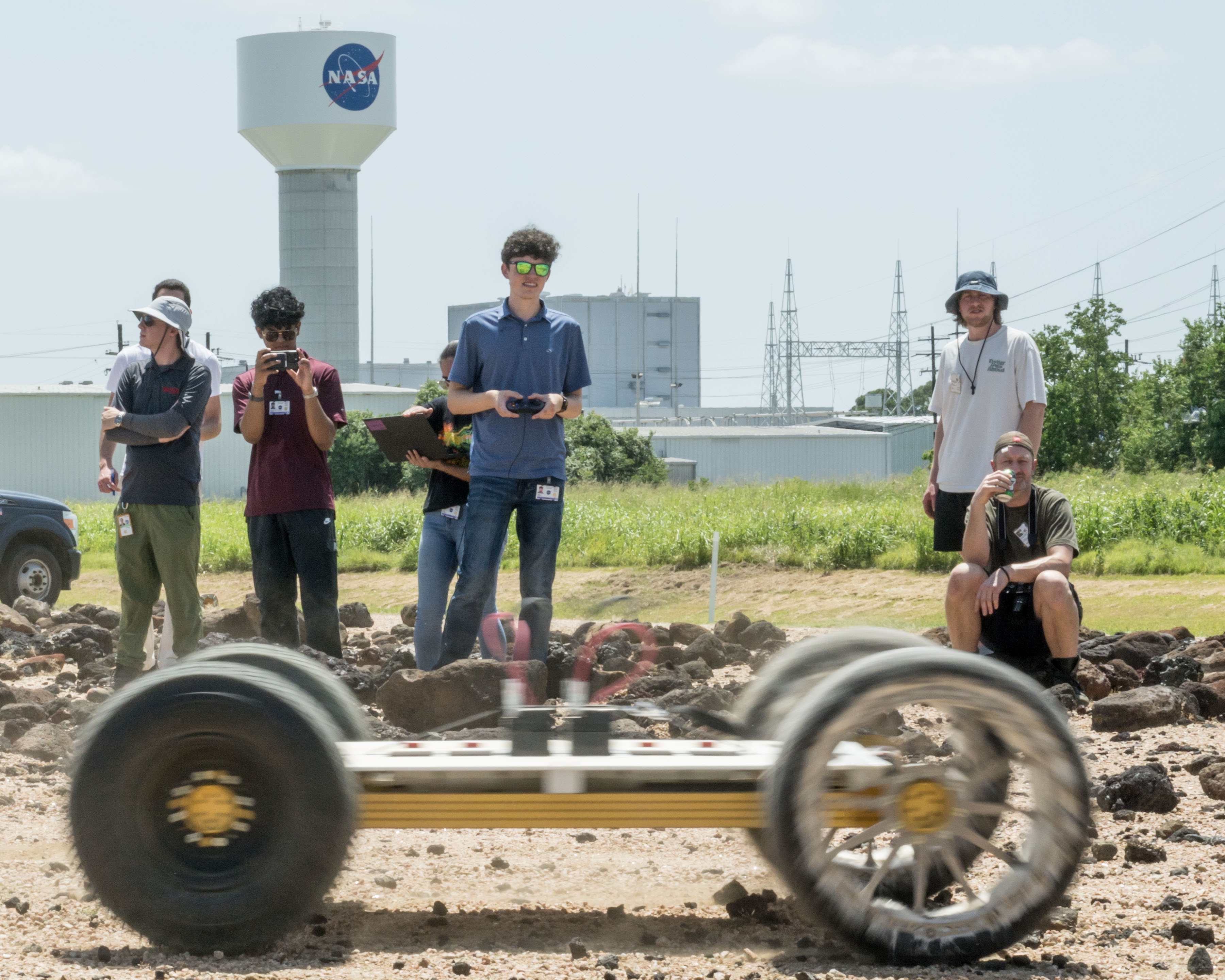
NASA Johnson uses ground prototypes to test mobility technologies, while lunar terrain vehicles will be delivered to the lunar surface through the Commercial Lunar Payload Services initiative. For the challenge, the wheels were fitted to MicroChariot, a 45-kilogram test rover, and put through a series of courses at Johnson’s Rock Yard to evaluate their performance across different types of terrain.
NASA Robotics Academy students navigate the lunar wheel prototype Scotch Pad Tyres fitted on the MicroChariot rover at Johnson’s Rock Yard.
NASA/Luna Posadas Nava
“Crowdsourcing gives us an opportunity to look beyond traditional approaches for lunar wheel design,” Herrera said. “The more wheel technologies we can develop and understand, the more options we have to meet the needs of different vehicles, terrains, and missions on the Moon and Mars.”
Those ideas were reflected in five distinctly different designs.
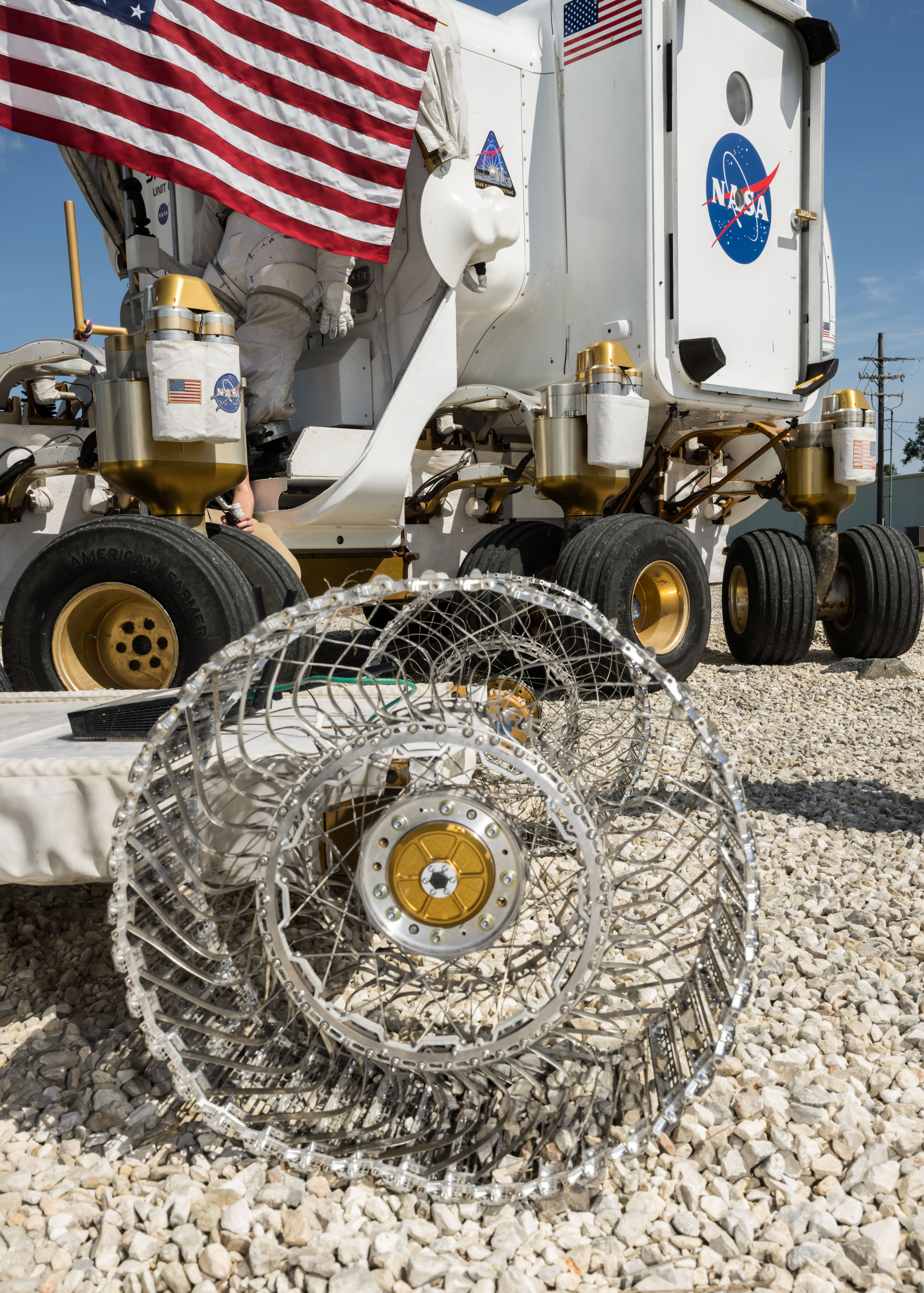
The HTR Variable Flex Lunar Wheel created by Hellenic Technology of Robotics SA uses an internal system designed to vary the wheel’s stiffness depending on terrain and vehicle needs. The team adapted technology it had been developing for terrestrial wheels for about a decade.
The Hiper Wheel created by Hyperbola uses tensioned cables and a corigated structure that provides spring-like behavior, allowing the wheel to flex without relying on traditional radial spokes.
The Huff Helo Flexible Titanium Wheel created by Huff Helo Inc. uses formed titanium sheet metal as both structure and spring. During testing, the team found that the strength of the design also made the wheel more rigid, causing it to bounce over some obstacles rather than conform to the terrain.
The Payne Aviation Wheel created by Deborah and Craige Payne took inspiration from aviation and history. Its designer, an aircraft mechanic, combined a pneumatic approach with ideas from early automobile tire designs.
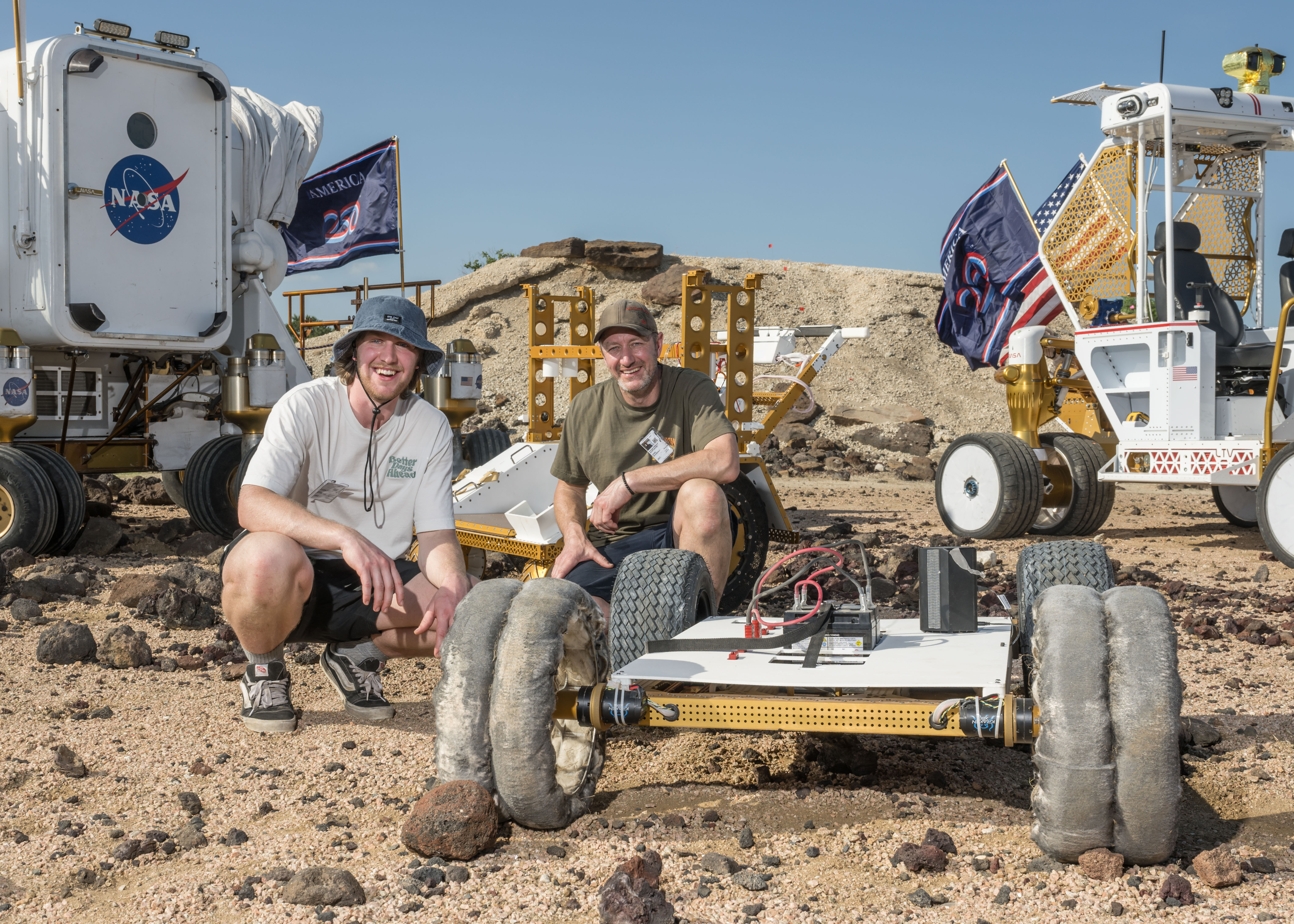
The winning Scotch Pad Tyres team poses with their prototype and MicroChariot at Johnson’s Rock Yard.
NASA/Luna Posadas Nava
The winning Scotch Pad Tyres concept came from an Australian mechanical engineer Daniel Bloomfield and his son Isaac Bloomfield. Their prototype uses a Nomex-based tire structure supported around an aluminum hub. The soft material allows the tire to deform around terrain, while internal support helps it maintain its shape. A treated outer surface of epoxy and corundum grit was integrated to improve traction.
The Rock Yard testing also demonstrated why different terrains may require different approaches. Loose material can affect traction, while rocks and slopes place different demands on wheels such as vehicle stability.
The HTR Variable Flex Lunar Wheel prototype sits alongside NASA’s Space Exploration Vehicle at Johnson’s Rock Yard.
NASA/Luna Posadas Nava
As lunar exploration expands, different vehicles will require different combinations of speed, load capacity, durability, and terrain performance.
Seeking that variety was part of the challenge design. The design options gave engineers different technologies to consider and potentially advance.
“This challenge brought in new ideas from outside traditional industries and helped us identify wheel technologies that may be suitable for longer-duration surface operations,” said Lucien Junkin, robotics engineer at Johnson and co-leader of the challenge project.
The next phase could evaluate how the wheels respond to lunar-like dust, vacuum, and extreme temperatures in Johnson’s thermal vacuum chambers. Engineers could also assess the designs over longer distances and at different sizes and loads.
“Mobility is key to everything we want to do on the Moon,” Junkin said. “The farther we want to explore, the more we need to advance the wheel technologies that can get us there.”
The Common Robotics Project of the Robotic Systems Technology Branch within Johnson’s Engineering Directorate conducted the Rock and Roll with NASA Challenge. NASA’s Center of Excellence for Collaborative Innovation, part of the Prizes, Challenges, and Crowdsourcing Program within the Research and Technology Mission Directorate, managed the challenge contract. Students in NASA’s Robotics Academy helped prepare hardware and support the competition, while engineers from NASA’s Glenn Research Center in Cleveland supported reviews of concepts and proposals. HeroX administered the challenge on behalf of NASA.
Preparations for Next Moonwalk Simulations Underway (and Underwater)
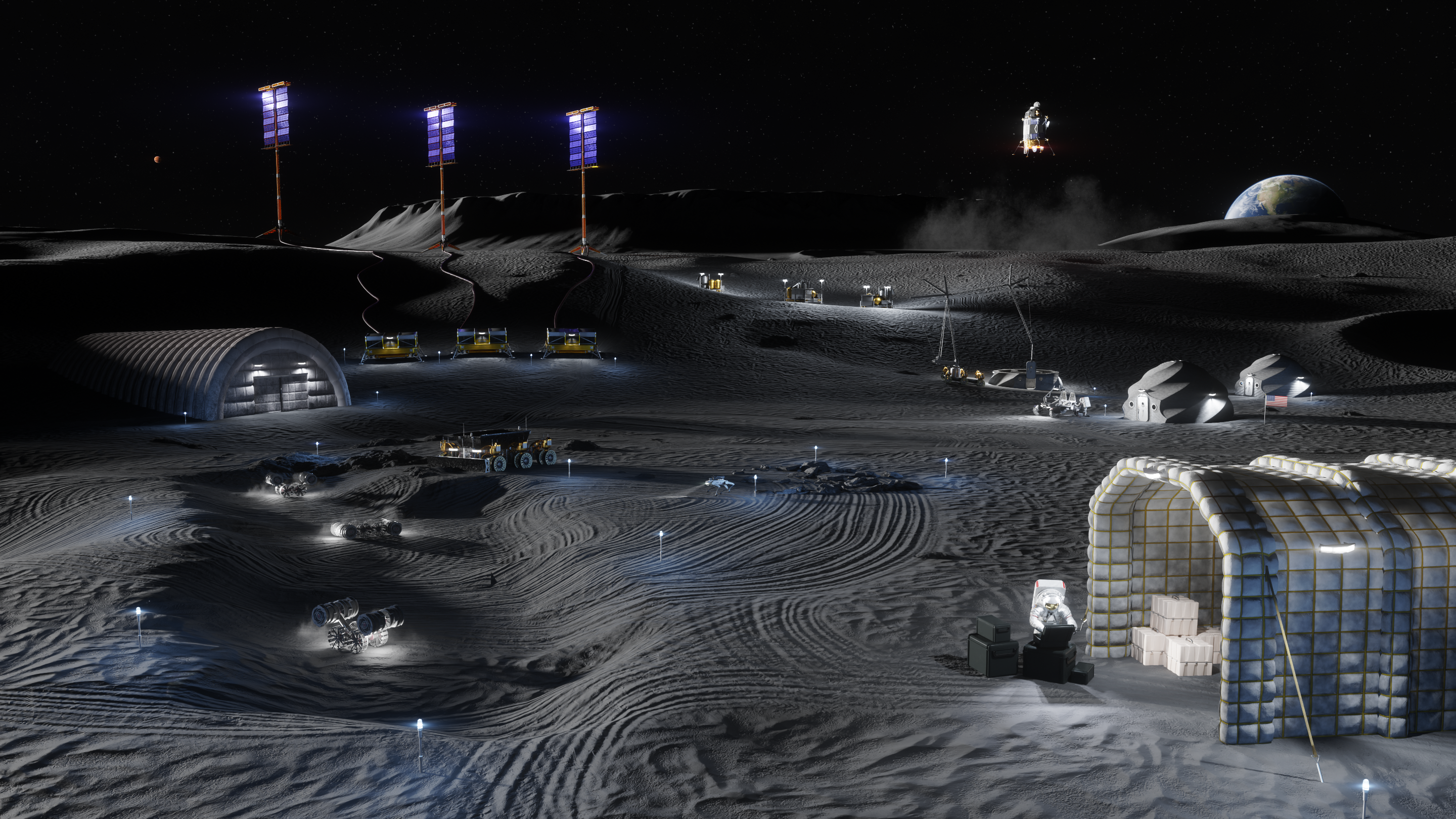
Artist’s rendering depicting lunar surface operations at a future base in the lunar South Pole.
NASA
NASA is asking U.S.-based collegiate teams to submit bold, original concepts to the 2027 edition of a student challenge focused on aerospace innovation that could help the agency envision a future on the Moon shaped by new technology.
The latest NASA Revolutionary Aerospace Systems Concepts – Academic Linkage (RASC-AL) competition invites student teams to explore new operations paradigms and advance the technologies needed to support sustained operations in the lunar South Pole region.
“This competition showcases the technical excellence and creativity of the next generation of explorers and innovators,” said Chris Jones, chief technologist, Systems Analysis and Concepts Directorate, NASA’s Langley Research Center in Hampton, Virginia. “The concepts students develop through RASC-AL demonstrate exceptional talent and contribute to the body of work that advances NASA’s missions.”
Since 2002, the annual RASC-AL competition has helped foster aerospace concepts, technology, and prototyping by making connections among universities, NASA, and industry. This year’s competition includes themes ranging from the development of concepts to support prospecting in the permanently shadowed regions of lunar craters to the advancement of critical and expandable infrastructure for future astronauts.
“NASA’s RASC-AL competition connects top university researchers with the agency’s technology and engineering challenges,” said Gabe Merrill, acting cross-program integration lead for the Advanced Research and Technology Division in NASA’s Research and Technology Mission Directorate. “By asking student innovators to design concepts for what our future on the Moon might look like, this competition accelerates the technology we need to explore the Moon and provides a development opportunity for future aerospace innovators and leaders.”
Teams interested in participating are required to submit a non-binding notice of intent by Tuesday, Oct. 13, and will be invited to a Q&A session with NASA experts on Oct. 27.
Challenge proposals and accompanying video submissions are due Feb. 24, 2027. Proposals should demonstrate innovative solutions supported by original engineering and analysis in response to one of the four 2027 RASC-AL themes:
Enabling extreme exploration
Transit pathway construction
Lunar resource exploration
Smart and resilient lunar habitat
The competition will select as many as 14 teams to advance to its final phase, which involves further developing their concepts, writing a technical paper, and creating a technical poster. Each finalist team will receive a $7,500 award to facilitate its full participation. Finalists will present their concepts to a panel of NASA and industry experts at the 2027 RASC-AL Forum in Cocoa Beach, Florida, June 7 to 10, 2027.
The top two overall teams will receive an additional monetary award and an invitation to attend and present their concept at an aerospace conference later in 2027.
Interested student teams are encouraged to visit the official RASC-AL competition website for detailed guidelines and eligibility requirements.
The 2027 NASA RASC-AL Competition is administered by the National Institute of Aerospace on behalf of NASA’s Advanced Research and Technology Division within the Research and Technology Mission Directorate. NASA’s Center of Excellence for Collaborative Innovation, part of the Prizes, Challenges, and Crowdsourcing Program within the Research and Technology Mission Directorate, manages the challenge contract.
NASA’s COFFIES Uses AI to Predict Storm-Causing Active Regions on Sun
As humanity looks to the Moon and stars for future exploration, predicting space weather — conditions in space primarily driven by the Sun — is more important than ever.
Now, a team of astrophysicists and data scientists with NASA’s COFFIES (Consequence Of Fields and Flows in the Interior and Exterior of the Sun) has developed a novel machine-learning model capable of predicting the emergence of active regions on the Sun up to 12 hours before they appear.
The Sun is constantly churning. Intense concentrations of localized magnetic fields can suddenly break through the solar surface, forming sunspots. Space weather forecasters then collectively number and track sunspots since they are visible manifestations of active regions, which serve as the main engines behind severe space weather events such as solar flares and coronal mass ejections. These eruptions send waves of high-energy radiation and charged particles across space, creating storms that can threaten astronauts, disable satellites, and disrupt radio communications on Earth.
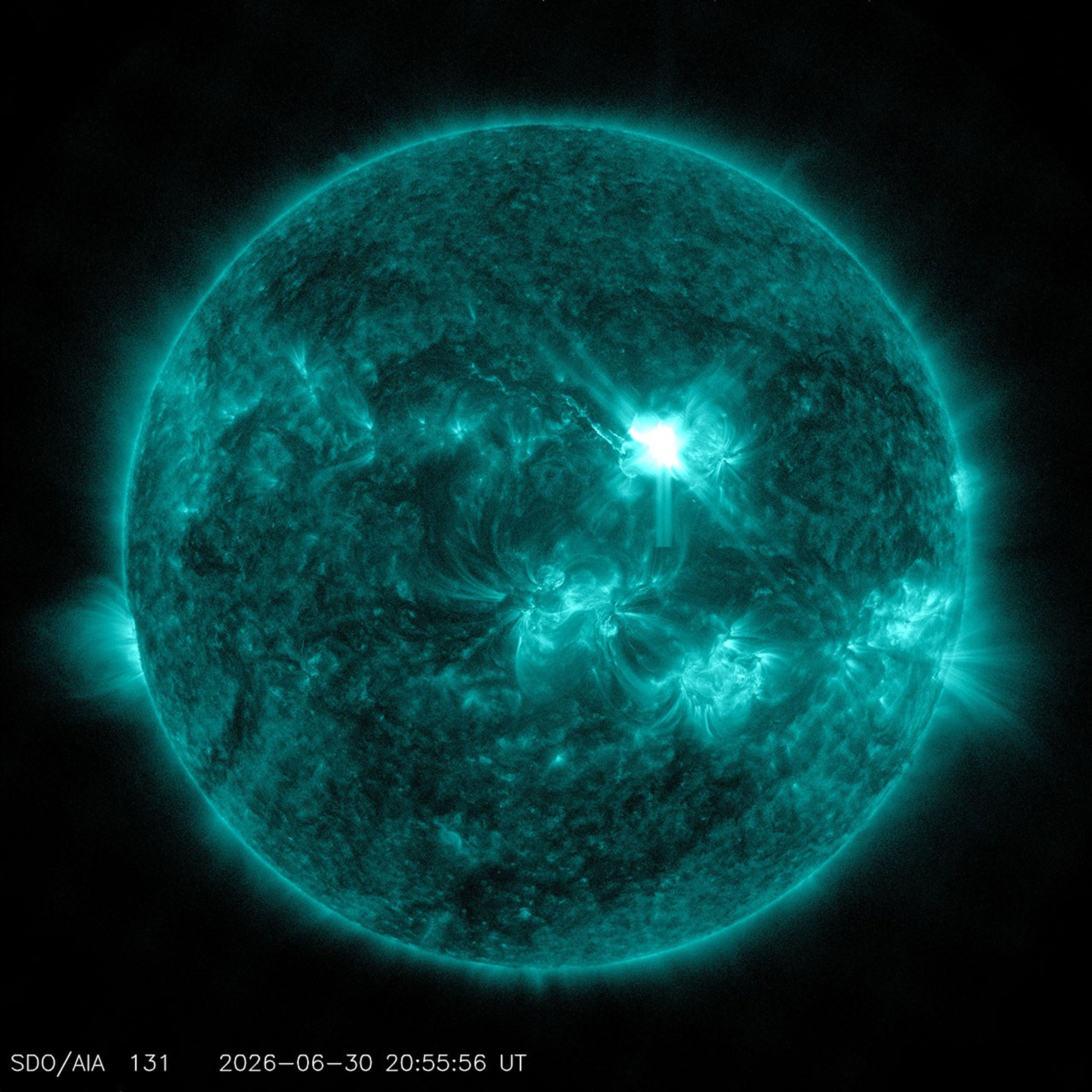
NASA’s Solar Dynamics Observatory captured this image of a solar flare — seen as the bright flash in the upper right — on June 30, 2026. The image shows a subset of extreme ultraviolet light that highlights the extremely hot material in flares and which is colorized in teal.
NASA’s Goddard Space Flight Center/SDO
By bridging expertise across different scientific institutions, COFFIES, a NASA DRIVE (Diversify, Realize, Integrate, Venture, Educate) Science Center, brought together a team of researchers from New Jersey Institute of Technology (NJIT), Princeton University, and NASA’s Ames Research Center in California’s Silicon Valley. The team turned to advanced artificial intelligence architectures — which dictate how data is processed and used to produce reliable predictions or actions — to capture subtle, time-based pattern changes on the solar surface before an active region took shape. By analyzing data captured by the agency’s Solar Dynamics Observatory and using NASA Ames’ supercomputing resources, this new approach, published in the Journal of Geophysical Research: Machine Learning and Computation, looks at fluctuations in acoustic waves caused by sunspot regions when the regions form beneath the solar surface and begin the journey upward to emerge on the surface.
“We cannot directly see the magnetic structure while it is still rising through the solar interior. Instead, we must look for indirect effects — very small changes in the magnetic field and in the pattern of acoustic waves continually traveling through the Sun,” said Alexander Kosovichev, a COFFIES co-investigator at NJIT. “The developed technique identifies precursors associated with an emerging active region in slight changes of the Sun’s acoustic power — more like a slight change in rhythm within a very noisy orchestra.”
This video is an example of what scientists use when analyzing the solar surface. This particular time frame tracks the magnetic field on the Sun’s surface during the emergence of active region AR11158 in February 2011. The blue square grid highlights a target area on the Sun. The squares on the right side translates the data from the target grid area to show opposing magnetic polarities, indicated by the warm and cool-colored tones. The first column of blocks shows targeted areas at original resolution, the middle column displays data as 2D maps, and the right column plots changes in magnetic polarity over time as 1D curves. By watching these blocks, scientists can see signs of active region emergence, such as drops in acoustic waves and rises in magnetic fields.
NASA’s COFFIES DRIVE Science Center/Irina Kitiashvili and Spiridon Kasapis
To develop current operational forecasts, the National Oceanic and Atmospheric Administration’s Space Weather Prediction Center and the United States Air Force monitor active regions that are already visible on the Sun to analyze the regions’ characteristics and estimate the probability of solar flares.
The COFFIES team aims to revolutionize this process. The AI model the team developed a specialized early detection system to handle very long sequences of data — called sliding-window transformer architecture — to use observations to find tiny reductions in the Sun’s acoustic activity and magnetic field, signals that scientists struggled to capture until now. These reductions form patterns that the AI model uses to predict active regions several hours before they become visible on the solar surface. Instead of looking at all activity on the solar surface at once, like earlier deep learning approaches have done, this new model moves a fixed-size “viewing window” across a long timeline of the Sun’s activity to focus on recent data while remembering overall patterns. This method allows forecasters the ability to predict approximate locations of emerging sunspots, rather than relying on counting already visible sunspots.
This promising AI architecture shows how deep machine learning can contribute to heliophysics — the field studying the nature of the Sun and how it influences the very nature of space and the planets that exist there. While the model is not ready for operational real-time forecasting, the team plans to validate the approach across many more known solar events to fine-tune the model.
NASA’s real-time space weather monitoring
As NASA focuses on sending humans to explore the Moon with the Artemis missions and sending the first crewed missions to Mars, monitoring and forecasting space weather is important for ensuring the safety of our astronauts and the equipment they rely on. This predictive leap from the COFFIES team could prove vital for safeguarding technology and deep-space explorers from the volatile environment of our solar system.
NASA’s Moon to Mars Space Weather Analysis Office monitors space weather 7 days a week. This important work helps decision makers not only protect people and equipment but maintain the services our modern society relies on every day. NASA’s space weather monitoring is also critical for safeguarding astronauts as they journey to the Moon and onward to Mars.
NASA/Lacey Young
Teams across NASA and NOAA collaborate to transition research capabilities into actual 360-degree space weather monitoring operational tools — including NASA’s Space Radiation Analysis Group, Moon to Mars Space Weather Analysis Office (M2M SWAO), and Community Coordinated Modeling Center as well as NOAA’s Space Weather Prediction Center. Sunspot region emergence prediction capabilities, especially of the Sun’s far side, could provide new information that supplements current models used by these teams.
“The COFFIES AI model is exciting to our team because it could provide us with new capabilities towards predicting potential flaring locations ahead of time,” said Michelangelo Romano, M2M SWAO deputy director. “With this heads up, we can provide additional support to NASA missions.”
NASA’s COFFIES is one of three DRIVE Science Centers created to encourage collaborative science by establishing centers that are made of multidisciplinary teams from several institutions across the U.S. These pioneering facilities employ modelers, theoreticians, computer scientists, and observers to study important mysteries of our star and its influence, a branch of science known as heliophysics.
The COFFIES team focuses on the interconnected processes behind the Sun’s activity. Understanding the Sun’s interior and magnetic variability is key to advancing our understanding of the Sun’s 11-year activity cycle and fine-tuning space weather forecasting tools.
As NASA sets its sights on long-term exploration of the Moon and Mars, the agency is increasing the cadence of its Artemis missions. Helping bring these plans to fruition is Tom Percy, manager of systems engineering and integration for NASA’s Human Landing System Program.
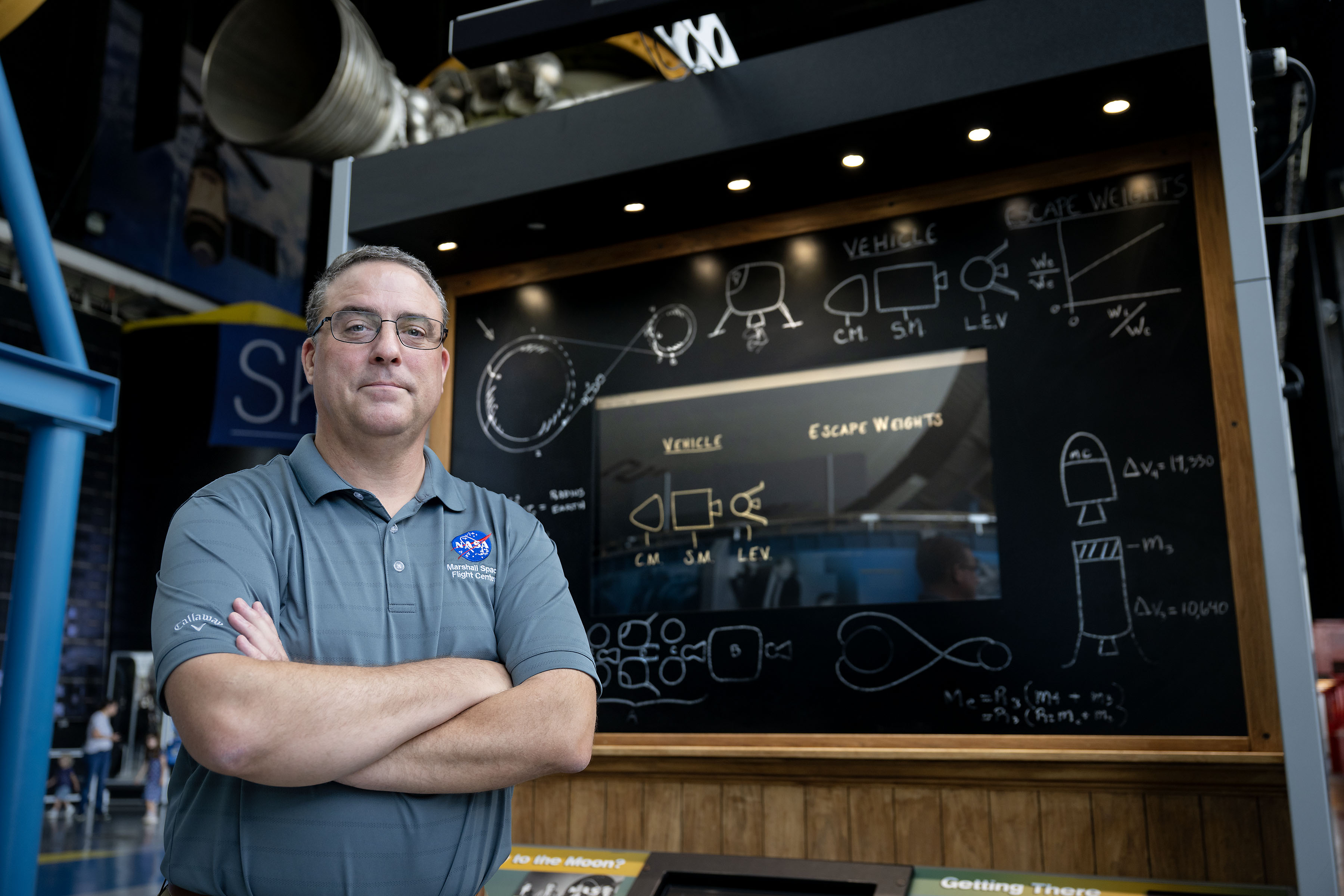
Tom Percy, manager of systems engineering and integration for NASA’s Human Landing Systems Program, stands in front of an Apollo Program lander exhibit at the U.S. Space and Rocket Center in Huntsville near NASA’s Marshall Space Flight Center.
NASA/Charles Beason
Percy serves as a focal point in working with providers SpaceX and Blue Origin to accelerate and streamline systems designs, manufacturing, testing, and certification. He ensures the crewed landers that SpaceX and Blue Origin are developing for Artemis are designed, built, tested, and will operate with other NASA exploration assets safely and effectively.
“You might say that all human landing system integration work lands on my desk. And with the rest of my talented, hard-working systems engineering and integration team, we’re working to make it all happen,” Percy said.
A native of North Easton, Massachusetts, Percy earned a bachelor’s degree in mechanical engineering from the Rochester Institute of Technology in Rochester, New York, where he first got hands-on experience working on designs that could be applied to NASA’s sustainable lunar architecture.
“As an undergrad, I served as president of the Rochester Institute of Technology’s chapter of the American Society of Mechanical Engineers. To get some real-world engineering experience, we decided to participate in the Great Moonbuggy Race,” Percy said. “Now called the Human Exploration Rover Challenge, the competition is held annually at NASA’s Marshall Space Flight Center in Huntsville, Alabama.
“At the time, I had never heard of Marshall Space Flight Center,” said Percy. “But our student team designed and built a rover and traveled to Huntsville for the race. That’s when I learned about some of the projects in Marshall’s diverse portfolio that the center works for NASA. And that’s when I began planning to make my way to NASA Marshall for my career.”
Percy chose to move south and earn a master’s degree in aerospace engineering from the Georgia Institute of Technology in Atlanta. His research in the advanced propulsion lab and courses in space systems design culminated in a spacecraft design course and the chance to work directly with engineers at Marshall.
Since landing at Marshall in 2003, Percy has been involved in evaluating transportation architecture options for human deep space exploration, including missions to land astronauts on the Moon and Mars. He also has expertise in space transportation, including advanced propulsion technology development; trajectory analysis; and spacecraft and mission concept development. Percy earned a doctorate in aerospace systems engineering from the University of Alabama in Huntsville.
The range of experience comes together in his current role as manager of human landing systems engineering and integration.
“The world watched the amazing success of Artemis II. NASA and our commercial providers are looking forward to flying again soon and executing increasingly complex Artemis missions,” Percy said.
Through the Artemis program, NASA will send astronauts on increasingly complex missions to explore more of the Moon for scientific discovery, economic benefits, establish an enduring human presence on the lunar surface, and to build on our foundation for the first crewed missions to Mars.

 Login
Login