Usually in Tech In Plain Sight, we talk about technology you probably see every day, even if you don’t notice it. But we hope you don’t get to see one of the latest crop of medical robots, such as the LUCAS chest compression system. If you watch the popular TV series “The Pitt”, though, you may have caught a glimpse of one of these medical marvels. They aren’t fiction. They are very real devices.
Calling them robots might be stretching the definition a little. They don’t roam the halls looking for patients. But once attached to someone in cardiac arrest, they can take over one of the most important — and physically demanding — parts of CPR: chest compressions.
Keep The Blood Moving
When someone’s heart stops pumping blood, time is critical. CPR doesn’t normally restart the heart on its own. Instead, chest compressions produce enough blood flow to keep oxygen reaching the brain and heart while rescuers work on the underlying problem and, when appropriate, use a defibrillator.
Doing that well is harder than it looks on television. Current American Heart Association guidelines call for adult chest compressions 100 to 120 times per minute, at least 5 cm deep but generally no deeper than 6 cm, while allowing the chest to recoil fully between compressions. Interruptions should be kept to a minimum.
That’s hard physical work. In fact, studies show compression depth begins to fall after only about 90 to 120 seconds, which is one reason CPR teams normally swap compressors every two minutes. But a robot doesn’t get tired.
Meet LUCAS
LUCAS stands for Lund University Cardiopulmonary Assist System, reflecting the device’s origins in Lund, Sweden. Early versions entered clinical use around 2002-2003 and were pneumatically powered. Later versions replaced the compressed-gas system with an electric motor and battery.
The current LUCAS 3 looks something like a small drill press straddling the patient as you can see in the video below. A backplate goes beneath the torso, and a frame locks onto it. An electrically driven piston presses a suction-cup-like pad against the sternum. Internally, the motor drives a belt and ball screw that moves the piston up and down.
Factory settings are around 102 compressions per minute and roughly 53 mm compression depth for a typical adult, although parameters can be configured.
Beyond tirelessness, another obvious advantage is that LUCAS doesn’t need hands. Medics can deal with ventilation, drugs, defibrillation, IV access, and the dozens of other things occurring during a cardiac arrest. More importantly, the device can keep compressing while a patient is being carried, wheeled through corridors, or transported in an ambulance — situations where doing good manual CPR is awkward and sometimes dangerous to the practitioner.
So Does It Save More People?
You might reasonably expect perfectly regular machine CPR to beat a tired human. Large randomized trials haven’t demonstrated that, however. The 4,471-patient PARAMEDIC trial found 30-day survival of 6.3% with LUCAS versus 6.8% with manual CPR, not a statistically significant difference. The 2,589-patient LINC trial similarly found essentially identical four-hour survival — 23.6% versus 23.7% — and no significant improvement in longer-term neurological outcomes.
That doesn’t make the machines useless. It says something slightly different: high-quality mechanical CPR hasn’t proven superior to high-quality manual CPR as a routine replacement. The International Liaison Committee on Resuscitation currently recommends against routine mechanical CPR, while specifically noting that it can be a reasonable alternative when sustained manual compressions are impractical or would endanger the practitioner.
One issue is setup. Installing the machine adds a time penalty: compressions must stop briefly while the backplate and mechanism are positioned. Good training is essential to keep that interruption short. Another problem is that some studies show potential links to higher rates of internal chest injuries, such as bleeding around the lungs. There have also been rare device malfunctions or power failures that can compromise care.
Not The Only Game In Town
LUCAS isn’t alone. ZOLL’s AutoPulse takes a very different mechanical approach. Instead of a piston pushing on one spot, a motor tightens a broad load-distributing band around the patient’s chest.
There’s also the German corpuls cpr, which returns to the piston idea but uses a cantilevered single-arm mechanism. That leaves much of the chest unobstructed and makes the system useful during procedures such as cardiac catheterization.
So perhaps these aren’t quite the autonomous robot doctors science fiction promised us. But when your heart has stopped, and a machine is tirelessly pumping your chest a hundred times a minute while the medical team works around it, you probably won’t complain. We hope you don’t have to find out.
We’ve seen DIY devices, though certifying medical devices for actual use isn’t for the faint of heart. Robots can also help train humans to do better CPR.
A few weeks ago, my wife was out walking the dog, and she sent me four or five photos of small orange boxes planted all around our neighborhood. (OK, I’ll bite!) They had little cards on them explaining that they were geophones, and a QR code on them that lead to a website with all the details. Munich was getting a large-scale seismic survey to map out our underground water, with the aim of using it for geothermal heat and power in the near future.
How do you map up to five kilometers under the earth? You pound the ground, sending shockwaves downward, and then listen for their reflections. At the boundaries between different layers, the change in the speed of sound in the different media cause reflections. Calculating the time it took for a given reflection to reach you lets you figure out how deep the layer boundary is.
The seismic survey procedure goes like this: geophones are set out at roughly 20 m intervals in lines spaced around 300 m apart that run roughly north-south, while “vibrotrucks” drive a roughly east-west course, creating mini-earthquakes every 20 meters along the way. Covering a surface of 1,000 km^2 with over 120,000 sample locations and exciting them 86,000 times is going to take a while. Lucky for me, they started in my part of town.
Hot Water
Because the earth is essentially a ball of hot molten metal with a thin and crispy outer crust, and because there is radioactive decay going on even within the crusty bit, temperatures rise as you dig down: roughly 30 °C per kilometer. And Munich has this fantastic source of water that’s folded under the earth in a layer that dates back to the Jurassic, which makes it both low in dissolved minerals and sitting just around 3 km down: at 100 °C. This turns out to be the sweet spot in terms of difficulty of drilling and heat gained from doing so.
Blessed with hot water underground, the question is how to best use it. The plan at the moment is to situate a number of geothermal plants around the city, drill relatively large bore holes at each site that reach down 1 km to 2 km, and then drill diagonally down after that to spider out into a larger source of water. This “extended reach drilling” pulls from a larger heat source, prevents cool spots, and has only recently become technologically feasible.
Which brings us to the GIGA-M study. A 3D map of the underground will help plan out where to put the geothermal plants, in which directions the runners will need to be drilled, and generally how to best coordinate the resource. There were a number of individual smaller surveys done over the last 20 years, and Munich and the surroundings already have a number of geothermal plants, but this survey aims to fill in all of the gaps.
The Hunter and His Prey
It was a Thursday morning when my wife thought she heard some pounding and humming outside. She was wrong, but it got us to look at the online map, and while they weren’t in our neighborhood just yet, they were probably within easy driving distance. I threw my camera and tripod in the car and headed out.
The Big Vibrotrucks
Out in the country, just outside of Grossdingharting (you can’t make these names up!) I spotted a plume of dust rising up from a field. Was it just a farmer tilling? Or was it a vibrotruck? I drove through the woods on a logging road, and when I came out, I was nearly face-to-face with the beasts.
They were loud, and I felt the rumble when I stepped out of the car, so I ran up and asked if I could film it. They said “sure”, and I set up the tripod. The first video I shot, apparently I hadn’t screwed the camera down hard enough in the tripod, and it vibrated loose. So I ran another 20 m further and tightened everything down.
I’m not going to lie: it was exceedingly loud and very exciting. I drove back home and couldn’t wait to review the footage.
The next morning, I heard the same sound outside my own house. They were driving vibrotrucks around in the field about a block up the street. I grabbed the camera and ran out barefoot to get footage. And then Saturday morning, while cooking blueberry pancakes for the family, they drove up my street. Am I stalking the vibrotrucks, or are they stalking me?
An engineer asked if they could stand in our front yard, so I took my chance to bombard him with questions. He seemed stoked to talk about it.
Geophones and Vibrotrucks
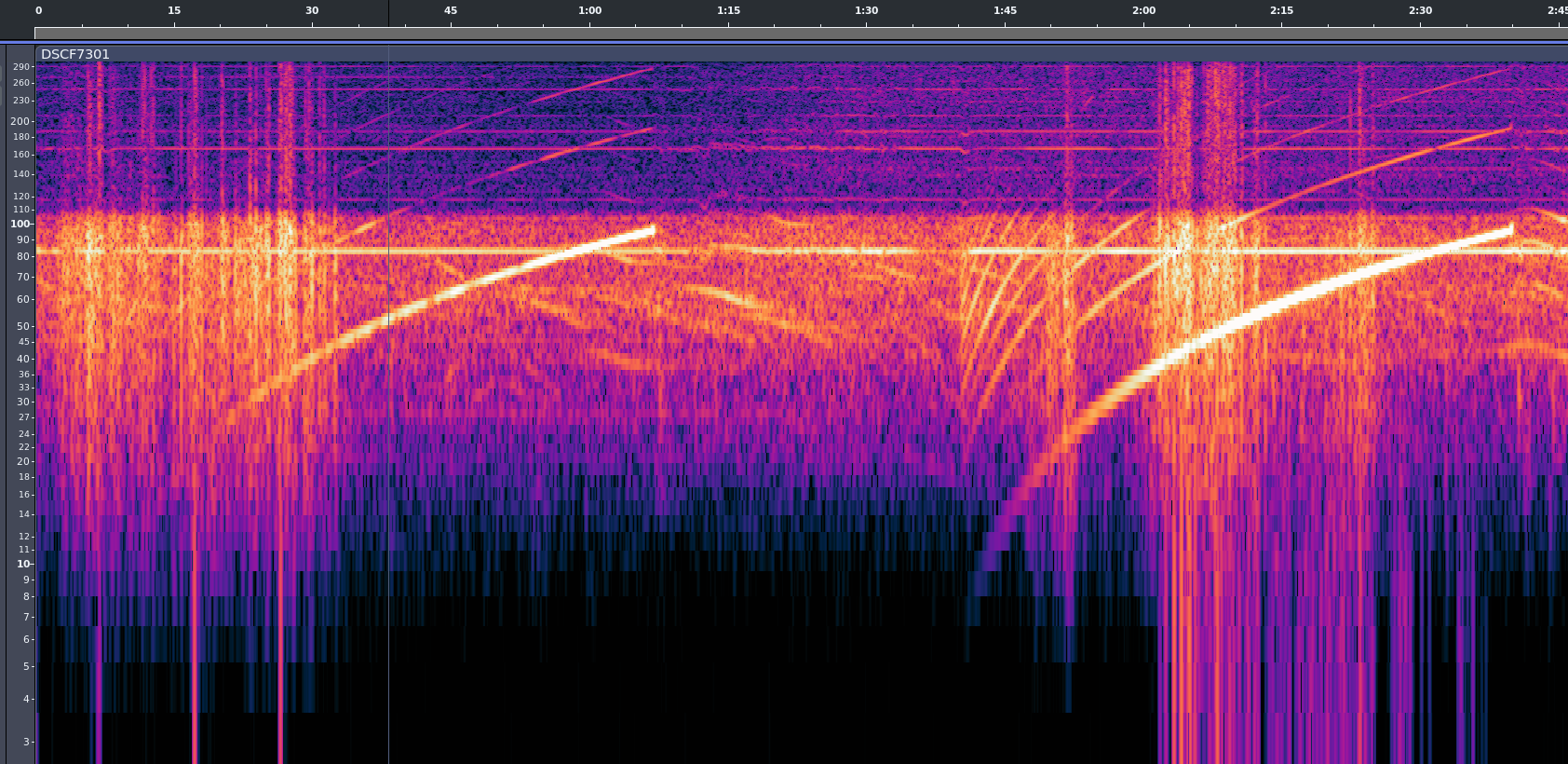
When you stand next to one of these things, first it shakes, and then you can hear a bassy tone, and then it rises and stops. They’re obviously doing a frequency sweep, much like you would use a sonar chirp to help disentangle the multiple reflections from one another.
The sweep means that even if they receive two reflections at once, they will hear two different pitches because one signal traveled further than the other, and comes from the earlier, lower-pitch part of the impulse. It also makes for a very easy to find signature. Correlating these times of flight across the entire array of geophones gives a 3D map of the underground layer discontinuities.
You can see from a cleaned up version of the audio that they’re sweeping from something like 6 Hz up to maybe 96 Hz. The lower end sounds like distinct hammering, and the top end a humming. Here is another video, with filtered audio. Because you feel the vibrations through your feet and in your chest, the live experience is a little bit like this with more noise. Play on good headphones or with a subwoofer for maximum effect.
Of course, the time of flight matters. I asked if each geohpone had a GPS timebase, and the friendly engineer told me that they individual geophones don’t – too expensive – but that when they install one, they connect it to a laptop with GPS that records the location and sets the geophone’s clock. When they harvest them, they record the location again, dump the time to verify that the clocks haven’t drifted too much, and then pull down all of the recorded timestamped data.
Why do they drive around in pairs? It’s simply because they make twice the vibration. The two trucks are actually synced together in phase, so they emit as one. The trucks have a GPS-disciplined clock inside, so they know exactly when they start each cycle and can derive the time-of-flight to all of the receiving geophones. The rest is math.
He also mentioned that it was too bad that I only got to experience the smaller “urban” vibrotrucks like the one outside my house. I kept my mouth shut – nobody needs to know that I’m a vibrotruck stalker.
I’m an experienced programmer, and I’ve worked in many different languages. Sometimes being a programmer is a two-edged sword. You want to accomplish something, and you can do it easily — but it can be a lot of work to do it right. Maybe more work than you want to do.
Normally, I’ll kick out a few lines of script for something I want and be done, accepting that it isn’t production-hardened. This time, however, I decided to try an AI tool to see whether they could do the work I was too lazy to do myself. While I’ve played with chatbots, I wanted to try one of the dedicated coding agents, in this case, Codex. Outside of asking ChatGPT to write a simple function or find the cause of an error message, I haven’t done much coding with AI assistance, so I was interested to see what these agents brought to the table.
A Radio Problem
The problem was simple: I wanted an easy way to put buttons on my Linux desktop that launched Internet radio stations. Sure, I could open a player and paste in a long URL, but I’m far too lazy to remember all those URLs.
I searched for a way to make Shortwave — an Internet radio player — open a URL from the command line. Apparently, you can’t. Google Gemini suggested writing a script that launches cvlc, the command-line VLC player, with the URL as an argument.
That’s easy, so I did it. Of course, then I had to find the stream URLs for all my favorite stations. It turns out that Radio Browser maintains an extensive database of stations. I considered scraping the site or using its API, but honestly, the little script was becoming too much of a project.
Besides, I was already struggling to manage the media player’s lifetime. I didn’t want a new station playing on top of one that was already running, and I wanted a command to stop playback, so the script had already grown larger than I first imagined.
My first version used a temporary file containing the player’s process ID so a future script execution could kill the old player. That usually works, but it isn’t very robust, and I knew it. But how much work did I really want to do here? I decided I had done enough and turned the rest over to Codex, OpenAI’s coding assistant.
What Can Codex Do?
Codex is more than a chatbot that produces code snippets. With access to a project, and limited access to your machine, it can inspect existing files, edit them, run commands and tests, examine Git history, and manage commits and remotes. OpenAI describes Codex workflows as including coding, testing, analysis, code review, and repository automation.
The important distinction is that Codex works on the actual project. Instead of copying code out of a chat window, I could say, “Have a look at this shell script,” and it examined the script in place. It also noticed that I already had an uncommitted modification and avoided overwriting it. It also understands version control, and that turns out to be one of its really nice features.
Fixing Problems
My first request was:
Have a look at this shell script. I know it needs a trap. Is there a better way to keep it from accidentally killing something with a stale playradio.tmp?
Codex pointed out that a trap was not the only solution. The launcher exits immediately after starting VLC, so it is not around later to receive SIGCLD or clean up after the player. Sure, it could run something to wait around, but there was a cleaner way to get the job done.
It initially suggested verifying that the saved PID still belonged to cvlc. Then it caught a subtler problem in its own proposal: if Linux reused the PID for a different cvlc process, the name check could still kill the wrong player. This is probably very rare, but when it does happen, it will be a mysterious, hard-to-reproduce bug.
The final solution records both the PID and Linux’s process start-time token:
Part of a Codex session. Entire transcripts are on GitHub.
Before sending a signal, the script confirms that both still match. It also uses a private per-user runtime directory, serializes concurrent start and stop operations with flock, sends SIGTERM first, waits for a graceful shutdown, and rechecks the process identity before falling back to SIGKILL. That is considerably more thought than I wanted to put into a desktop radio button. Overkill? Maybe, but it is robust.
Another pleasant surprise was that Codex built a suite of tests to ensure that everything worked as it should. It runs these tests when it makes changes. So it doesn’t just create code. It creates code, executes it with test cases, and fixes any issues it discovers.
Searching the Database — and More
Once the process handling was safe, I asked:
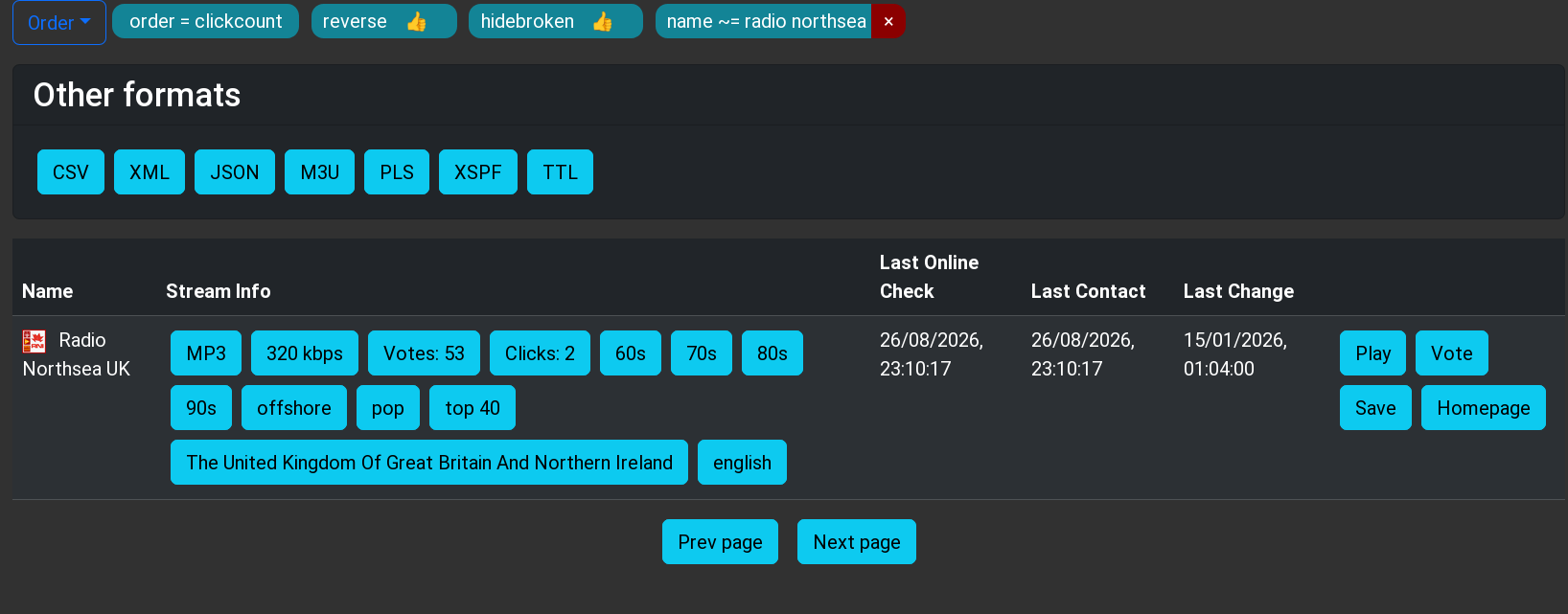
Radio Browser allows you to search via API for radio stations. How hard would it be to make $1 a search string and take the best match, while allowing -u for a URL instead?
Codex checked the current API documentation, found that curl and jq were already installed, and implemented the search. It hides broken stations, orders matches by votes, selects the top result, and reports the selection back to Radio Browser’s click counter. I told it I wanted specific command-line options over several iterations. The program can play a URL, search the database for a station, or even just query the database. It can also give you a list and let you pick. (See the README.md for the entire interface.)
RadioBrowser is human-readable, but also provides the same data via API.
I did make a few requests. For example, if you pass a URI, the program should figure it out and skip the database search. I also wanted the player to be configurable through a PLAYRADIO_PLAYER environment variable. I asked it to fall back on wget if curl wasn’t installed. Missing dependencies should produce useful installation advice rather than mysterious failures. I also asked it to produce a GitHub-style README and a traditional Unix man page.
Human Guidance Still Matters
There were a few places where human intervention improved the result. For example, the PLAYRADIO_PLAYER configuration and its explanatory comment originally appeared near the bottom of the script. That works, but it is inconvenient for someone who wanted to edit the file. I asked Codex to move it near the top.
Another example was the first version of --pick. I had specifically suggested Bash’s select command, so Codex printed the formatted list and then let select print a second numbered list. It worked, but the duplication was distracting and, as far as Codex was concerned, it was what I asked for.
I pointed the duplication out. Codex replaced select with a simple numeric read, keeping the detailed table and adding only one extra row:
1 Jazz One
2 Jazz Two
3 Cancel
Station number:
This is a good example of how I think these tools work best. The AI handles the implementation, edge cases, tests, and documentation, while the human provides design input and flags anything awkward or that doesn’t fit the intended experience.
Does It Scale?
I’m not an expert at using these kinds of tools, but I think this worked very well. I generally asked for what I wanted and then made technical observations about the results.
I also tried this with a script, originally from [Petar Marinov], that I’ve used and modified for years to replace the cd command (see GitHub). I didn’t tell it what to do. I just let it look at the code. It correctly determined what it was supposed to do and made solid suggestions for making it more robust. It suggested features and even a major improvement to make it work not just with cd but with anything that changes pwd, like pushd. Of course, I couldn’t resist getting a man page and a README for free.
One feature I asked the tool to create was a simple bookmark system. It proposed and created a way to create and maintain a bash associative array that it persisted in a configuration file. That worked, but I knew it would be better, on many levels, to keep the bookmarks as proper symlinks. When I pointed this out, the AI did get it, saying:
That has several nice consequences:
changes from cdmark are instantly visible in every shell; no reload or synchronization issue
ls -l ~/.config/cdfunc/bookmarks is already a crude cdmark list
bookmarks can be created or removed manually with ordinary Unix tools
Syncthing/git/backup tools handle them naturally
no parsing, quoting, escaping, or rewriting a bookmarks file
no associative-array initialization at shell startup
broken bookmarks are naturally represented as broken symlinks
I think that’s substantially cleaner.
It also noted that this makes shell completion very simple, which I had not thought about. However, its implementation broke normal shell completion for the commands. It fixed that after I pointed it out. Well, actually, it took two tries to work out all the bugs. This is another case where human guidance is critical.
For a more advanced project, I forked a simple editor, kilo, and added a few Emacs commands. I asked Codex to review it. It found a number of bad edge cases, some in the original code, and fixed them. I then asked it to suggest Emacs-like features it could easily do. We added a ton! (see GitHub). It was impressive how well it analyzed and understood the code. I had done similar modifications to the code a few weeks earlier and, I have to admit, Codex understood the original code base much faster than I had.
Again, though, human guidance is necessary. Emacs uses an Esc prefix for some commands. You can also hold down the Alt key to get the same result. So pressing Alt+W in a terminal sends an Esc character and a W.
Initially, Codex wrote code to detect an Esc, wait a short time for a command, and then, if nothing came, treat it as a bare escape. It even understood that this would be a problem and mentioned it. Alt+W would work, but there was no way for a human to press Esc and then W in the time allotted. I prompted:
Yes I see that in the program. Would it be possible to have it wait indefinitely for ESC UNLESS a caller set some flag. So when other parts of the editor (search/save/etc.) are prompting for input they would set that flag (or call a separate entry point) and, at that point, ESC=>ESC. Any other time ESC is treated as a prefix (and perhaps ESC ESC gets sent as an escape just as a — ahem — escape hatch.
That fixed the problem. It is hard to remember that while Codex seems smart, it doesn’t have human judgment or human-level problem-solving skills. You have to supply that. Sure, it found problems in its own code. It found problems in my code. It devised solutions. But you still have to make sure those solutions make sense and sometimes nudge it — at least — in the right direction.
If you are interested, each of the GitHub repos (playradio, cdfunc, and kilo) has a session directory that contains transcripts of the AI chats that produced the final versions of the code. Admittedly, none of these started from a totally blank slate, but working on an existing code base is certainly a realistic test.
The Git Assistant
One feature I particularly liked was Codex’s ability to manage Git. I didn’t even try the GitHub plugin for Codex, which would probably be even better. I asked it to commit the current version before starting a new feature, which gave me a clean checkpoint. Later I said:
Commit please. I’m going to add a remote GitHub repo. Can you set this as origin and push it after the commit?
Codex committed the changes, added the remote, pushed the branch, configured upstream tracking, and verified that the working tree was clean. The entire evolution is visible in the repository’s history — from process-safety changes, to Radio Browser search, to configuration and documentation, to the interactive station picker.
You can see the final project and follow each commit in the repositories along with transcripts of the AI sessions. Having things in version control is especially useful with a tool like Codex. You can easily see what has changed and roll back if you like.
Wrap Up
The original script solved my immediate problem in a handful of lines. The finished utility solves the same problem safely, handles failures, searches a public database, supports different players, has good documentation, and leaves a traceable Git history. One important note. Codex and other agents have a limited context window, so you won’t get the same results trying to work with extremely large code bases unless you pay for a larger model. But for these tasks, normal consumer Codex worked well.
Could I have written all of that myself? Certainly. Would I have bothered to go this far? Probably not for what is basically a one-off desktop hack.
That may be the most useful role for a coding agent: They don’t always enable you to do something you couldn’t otherwise do. But they make it cheap enough in time and attention span to do all the boring and defensive coding and testing that you know you should do, but so often don’t. Codex didn’t replace me. It just augmented my patience.
If you used a scientific calculator in the 1970s or 1980s, there was a fair chance that it worked differently from almost every calculator you see today. Instead of typing:
2 + 3 =
you entered:
2 ENTER 3 +
There wasn’t even an equals key. Hewlett-Packard made this system — Reverse Polish Notation, or RPN — practically synonymous with serious scientific calculators until other players like TI and Casio got serious. Once you got used to it, ordinary algebraic calculators could feel annoyingly clumsy.
Today, RPN calculators look like a nearly extinct species. HP left the calculator market, licensing the HP calculator line to Moravia Consulting. Old HP-15Cs, 16Cs, 32Ss, 42Ss, and 48s have become collectibles. But RPN isn’t dead. You can still buy new hardware, build your own, or turn almost any computer or phone into a very capable RPN machine. There are reasons some of us still want to.
But Why Polish?
The name goes back to Polish logician [Jan Łukasiewicz], who devised a notation in which operators precede their operands. Instead of writing:
A + B
you can write:
+ A B
The big advantage is that parentheses aren’t required. The structure of the expression tells you exactly what operates on what. Reverse Polish notation simply puts the operator at the other end:
A B +
[Łukasiewicz] wasn’t designing calculators, of course, but the same idea turned out to be extremely convenient for computers and calculators. Your software doesn’t have to remember what operation is in progress. Each operator is ready to go and can simply work on the operands that you’ve already read.
RPN isn’t exactly the way people calculate with pencil and paper, and it certainly wasn’t derived from the slide rule, but there is a similarity in the way you work. With a slide rule, you generally establish some value, operate on it, and continue from the result. When doing a long-hand calculation, you often calculate a subexpression, write down the answer, and use that answer in the next step. You will probably start with the inner parenthesis and work outward, just like someone with an RPN calculator does. RPN formalizes that process with a stack.
Suppose you want:
(3 + 4) × (5 + 6)
On a conventional calculator, you either need parentheses, or you have to calculate one result and remember it. On an RPN calculator:
3 ENTER

4 +

5 ENTER

6 +

×
The first + leaves 7 on the stack. The second leaves 11 above it. The multiply consumes both and leaves 77.
Notice what’s missing: parentheses, an equals key, and any need to tell the calculator about precedence. This isn’t much of a win for a five-key calculation. It becomes more apparent with something like computing the value of a bunch of parallel resistors:
R=1/(1/R1+1/R2+1/R3…)
An RPN user can calculate each reciprocal, add it to the running result on the stack, and finally take the reciprocal. Intermediate answers stay in the calculator naturally instead of being stuffed into memory registers or enclosed in increasingly impressive collections of parentheses.
Is RPN better? Calculator users have been arguing about that for half a century. But once RPN gets wired into your fingers, it can be surprisingly hard to give up.
RPN Before HP
Although RPN and HP are nearly inseparable in popular memory, HP didn’t invent the RPN calculator. That distinction generally goes to the Friden EC-130, introduced in 1964. It was a 44-pound transistorized desktop calculator costing $2,150, and its CRT actually displayed all four levels of its RPN stack at once. More than 18,000 were eventually made. You can even simulate it in Verilog, if you like.
HP entered the business in 1968 with the HP 9100A, a programmable desktop scientific calculator. It weighed about 40 pounds and sold for $4,900, but it provided logarithms, trigonometry, hyperbolic functions, coordinate conversion, programming, and RPN operation. HP famously called it a calculator rather than a computer partly because customers could often buy calculators without getting corporate computer departments involved.
Then came the machine that changed everything: 1972’s HP-35, the first HP pocket scientific calculator. From there, RPN became a defining characteristic of HP calculators for decades.
There were financial calculators, programmer’s calculators, scientific calculators, graphing calculators, and eventually the RPL machines such as the HP-28 and HP-48, which generalized the stack idea into an entire programming environment.
Eventually, though, algebraic entry won the mass market. Even HP began producing machines with algebraic modes, and some later calculators let you choose either system.
So did RPN die out? Are there any RPN machines left in 2026? Quite a few, as it turns out. The real question is do you want a calculator that pretends, in some way, to be your favorite old-fashioned RPN calculator, or do you want a more modern device that happens to use (or, at least, is able to use) RPN?
RPN You Can Still Hold In Your Hand
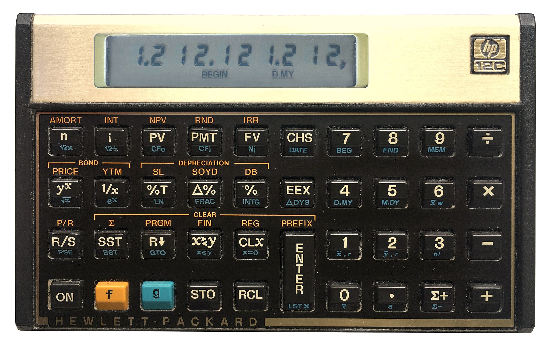
You can still get an HP12C (public domain).
The strange survivor is the HP-12C. Introduced in 1981 as a financial calculator, it remains available new more than four decades later. Depending on the retailer, expect something around $50 to $70. The 12C Platinum, which can operate in either RPN or algebraic mode, is also still available for roughly $80 to $110.
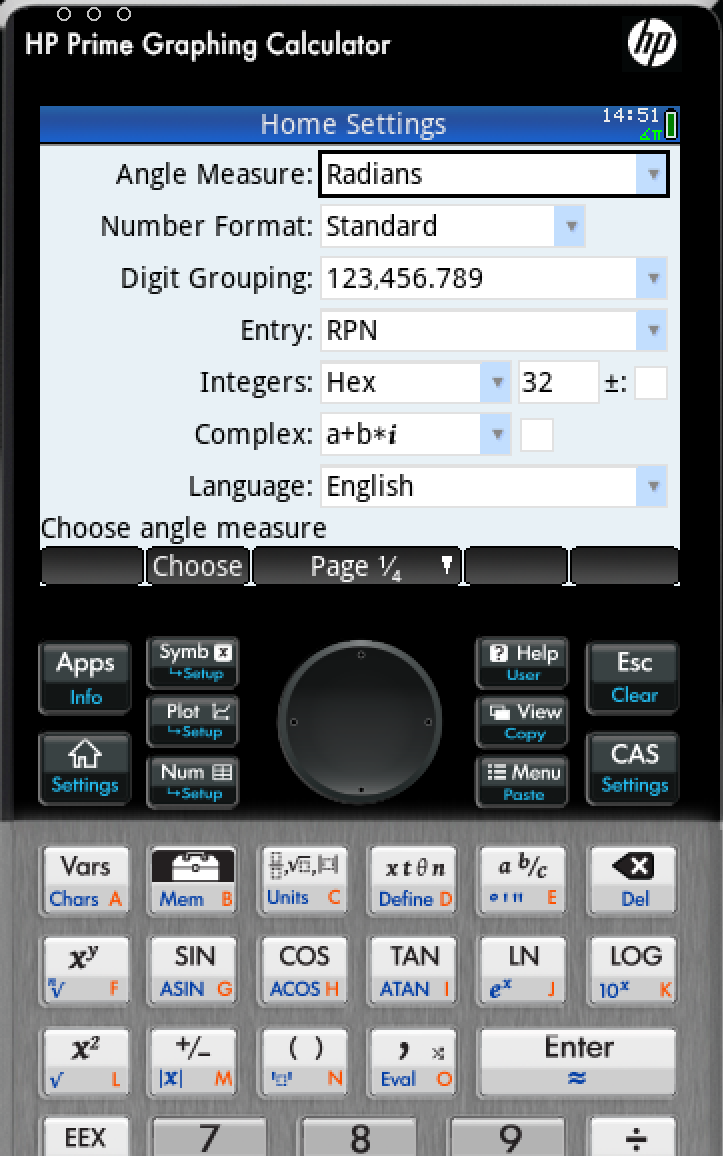
Then there is the HP Prime G2, generally around $150 to $170. The Prime is a graphing calculator with CAS, programming, symbolic mathematics, touch screen, and textbook-style input — but buried among all of that is an RPN entry mode. It isn’t an old-fashioned HP RPN calculator, but it certainly qualifies.
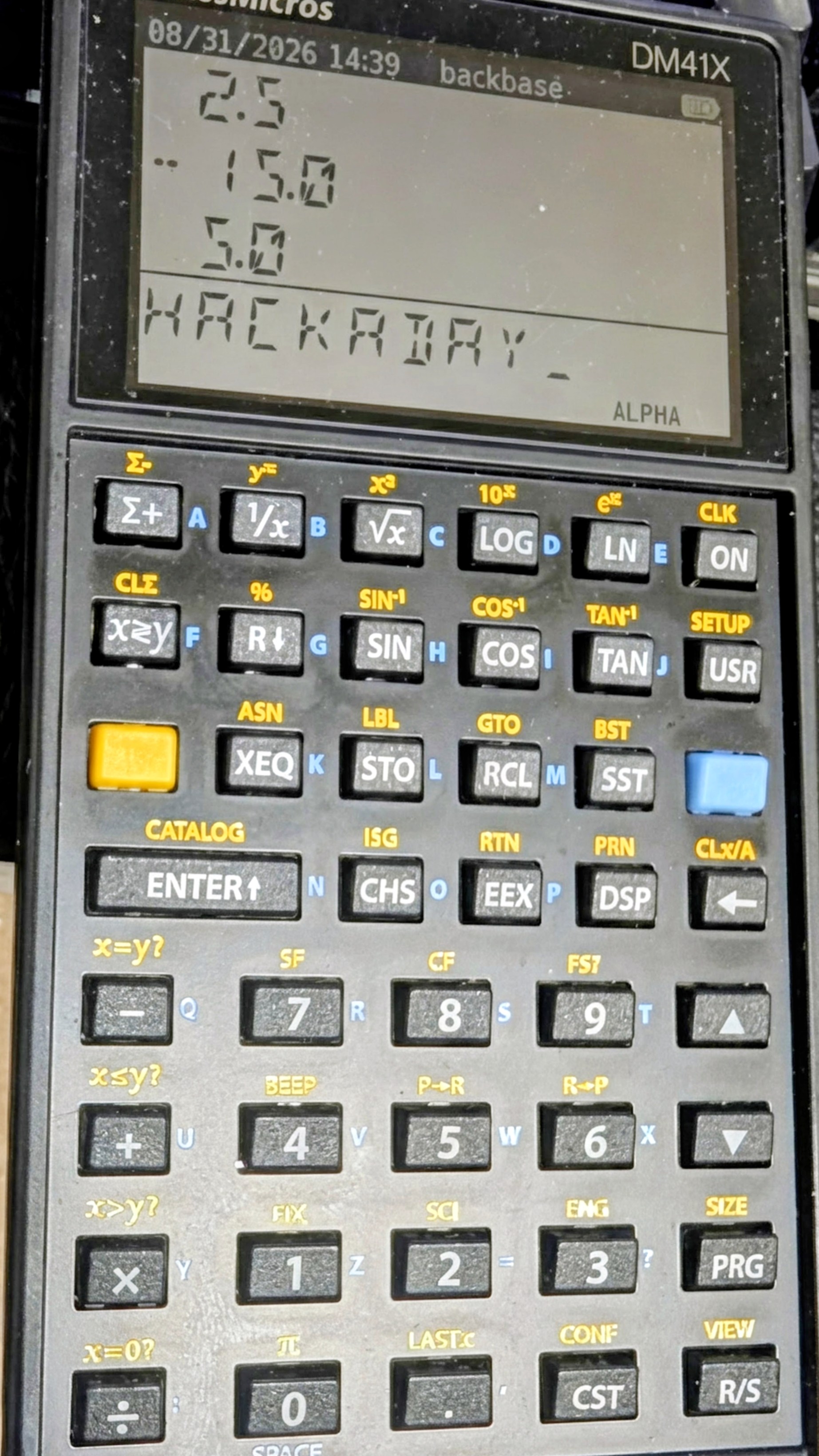
The real center of new RPN hardware today, however, is SwissMicros. SwissMicros started by producing modern implementations of classic HP designs and has since moved well beyond simple reproduction. Its current machines include the DM15L, modeled after the HP-15C; the DM16L programmer’s calculator; DM41L, DM41C, and DM41X machines inspired by the HP-41 family; and the DM32, which occupies roughly the territory once covered by the HP-32SII.
The SwissMicros answer to the HP41C (thanks [Julian]).At the high end is the DM42n, a modern descendant of the HP-42S idea. It has a 400×240 display, USB-C, programmable operation, matrices, complex numbers, equation solving, numerical integration, and 34-digit decimal arithmetic. It currently sells for a bit more than $300.
Perhaps more interesting is the R47, at about the same price. Instead of recreating a particular HP calculator, it grew out of the WP34S/WP43 community projects and attempts to be a modern enthusiast’s RPN calculator. It has an eight-level stack, matrices and vectors, complex arithmetic, base-N and bit operations, statistics, units, financial calculations, equation solving, integration, programming, and even built-in electrical engineering functions. Its firmware is still officially considered beta. This is probably the closest thing today to somebody asking, “What calculator would an obsessive HP engineer build if we started over?”
SwissMicros calculators aren’t cheap. Depending on the model, you’re generally looking at roughly $180 to more than $300 after currency conversion. But they are real, currently manufactured calculators rather than 40-year-old collectibles.
Heat Up The Soldering Iron
Sure, a real HP41C is in portrait mode, but otherwise, [Garza’s] is a pretty good clone.There is also a suitably hacker-friendly route. [Alex Garza’s] PAXER calculator projects reproduce machines such as the HP-15C, HP-16C, and HP-41C using an ATmega328. They’re available in kit form, use through-hole components, and aren’t just empty cases containing old calculator electronics.
The ATmega scans the keyboard, drives the display, and emulates the original machine. The design adds such modern amenities as continuous memory, an LCD backlight, real-time clock, and considerably higher execution speed than the originals. Kits and assembled versions are typically under $100.
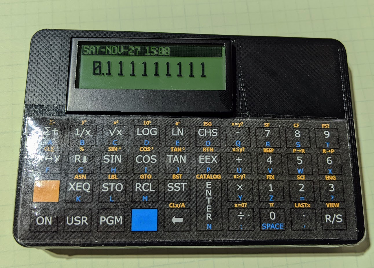
There is also the 10LC (and related models), which approaches the problem from the other direction: take inexpensive ESP32-based M5Stack Cardputer hardware, add calculator firmware and key labels, and turn the whole thing into a pocket RPN calculator. Figure roughly $50-$60.
It isn’t going to make a calculator collector forget an HP-42S keyboard, but it does show how little hardware is actually required to build an extraordinarily capable calculator today.
There’s An App For That
CalcTastic is a modern RPN phone app.If physical keys aren’t mandatory, RPN is actually thriving. You can get a host of RPN calculators on your Android or iPhone. There are many options for desktop computers, too. You can generally find these on your platform’s program repositories.
One of the best places to start is Free42, [Thomas Okken’s] free, clean-room implementation of the HP-42S. It runs on Android, iOS, Windows, macOS, and Linux. Plus42, from the same author, takes that foundation and expands it with equations, units, directories, plotting, financial functions, and other capabilities that the original HP-42S never had.
Android users also have CalcTastic, which can switch between algebraic and RPN modes and provides scientific calculation, complex numbers, fractions, statistics, conversions, and — in the paid version — programmer functions. The basic version is free, and the Plus version is only a few dollars.
For the HP-48 crowd, there is Droid48 on Android and several HP-48 implementations on iOS. If your idea of a calculator includes directories, symbolic objects, programs, lists, and an RPL command line, the phone in your pocket can impersonate a 48 far faster than the original hardware ever could. If you prefer the HP41C, go41C is the one I like.
Apple users have an especially large selection. i41CX recreates and extends the HP-41 environment. PCalc isn’t primarily an RPN calculator, but has long offered a very good RPN mode. There are also modern RPN calculators including MathU, RPN Calc, RPN Calculator 48, and a growing number of simulations of individual classic HP machines.
Real HP
Even HP’s current flagship environment is available in software. HP Prime Pro runs on Android and iOS and supports optional RPN input.
Desktop users aren’t left out either. HP provides a free HP Prime Virtual Calculator for Windows, and there has also been a macOS version. Most unusually, HP once produced an actual native Linux version. The Linux release was packaged as an AppImage and survives as a 2019 technical preview — build 2.1.14288 in the copy sitting on my Linux machine. It isn’t the Windows version hidden inside Wine; it’s a native HP build, and it still works remarkably well. Unfortunately, it predates one particularly interesting addition to the Prime: Python programming.
The HP Prime needs a setting to change to RPN mode.
There is a way to get that on Linux, although HP doesn’t make it easy. I found that the December 2024 Windows release of the Virtual Calculator, version 2.2.15212, runs under Wine using the Soda 9 runner in Bottles. That version includes the Prime’s Python app and reports MicroPython 1.9.4. The catch is that you don’t want to accept its offer to upgrade. Updating to the current Windows version causes the simulator to stop working under the same setup, and Soda 11 doesn’t appear to fare any better. So there is a slightly absurd sweet spot where an older Windows Prime under an older Wine runner provides a more up-to-date Prime on Linux than HP’s own native Linux build.
Between Free42, Plus42, Prime, HP-48 emulators and innumerable smaller projects, software may actually be the easiest way to use RPN today.
The Used Option
Of course, another source is available: millions of old calculators are already out there. If you’ve always wanted an HP-11C, 15C, 16C, 28S, 32SII, 41CX, 42S, or 48GX, auction sites and used-equipment dealers will happily provide one. Sometimes you can still find a bargain, especially if you’re willing to buy a cosmetically ugly machine or something outside the most desirable models. The problem is that the best old calculators aren’t merely used calculators anymore. They’re collectibles.
A calculator that originally lived in an engineer’s shirt pocket may now be a pristine example with its case, manuals, and box — and priced accordingly. Even fairly ordinary examples of desirable models can sell for enough money that carrying one around every day starts to feel irresponsible. My treasured HP41C, for example, works fine, but is already scuffed up enough that I rarely risk using it at my desk these days.
That creates a slightly absurd situation. A perfectly functional 35- or 40-year-old calculator may cost considerably more than an astonishingly capable modern computer because one is being priced as a collectible and the other as a tool.
On the other hand, battered calculators exist. If you don’t care about scratches, engraved names, missing battery doors, or someone’s old asset-control sticker, those are often exactly the machines to buy. You’re going to use it, after all.
ENTER Isn’t Dead
RPN plainly lost the calculator wars. Walk into an office supply store, and almost every calculator on the shelf expects conventional algebraic input. But it didn’t disappear.
You can still buy an HP-12C. You can buy sophisticated new RPN machines from SwissMicros. You can solder together your own HP-inspired calculator around an 8-bit AVR. You can turn an ESP32 gadget into one. Or you can install an app and have an HP-42S, HP-48, or modern RPN calculator in your pocket for anywhere from nothing to a few dollars.
That’s a surprising amount of life for an input system the mainstream calculator industry decided we didn’t want decades ago. Then again, people who like RPN tend to really like RPN.
If 2 ENTER 3 + looks more natural to you than 2 + 3 =, apparently somebody is still willing to sell you a calculator. If you want to see how easy it can be to parse RPN in a program, we’ve done that.
There are many ways to detect stress in an individual. You can use self-reporting checklists, you could try and measure various vital signs like respiratory rate and pulse and infer things, or you could observe the levels of hormones like cortisol in the blood.
Or… you could pull some parts out of a Playstation 4, and get hacking. Edwin Hwu did precisely that, creating a device that can image the skin down to the nanometer and potentially even determine fine details about an individual’s health status. He came to Hackaday Europe 2026 to tell us all about it.
Look Closely
Edwin’s background is very relevant to this project. He worked in a research institute in Taiwan where he collaborated with the German National Metrology Institute, working on atomic resolution imaging on silicon wafers. When you’re doing sub-nanometer calibration work for the semiconductor industry, that’s serious stuff, as is the X-ray microscopy that Edwin has dived into. When it comes to looking at things at very tiny scales, he knows his stuff. He’s also done plenty of work on real-time cell culture monitoring, skin assessments, and even high resolution 3D printing. It’s a broad skill base that all fed into the project he came to Hackaday Europe to talk about.
A single strand of DNA imaged with a DVD-based AFM setup. Credit: talk slides
There is a problem with optical microscopy that comes down to the diffraction limit of light—which means you can only image down to a resolution of around 1 micrometer. That’s why we use scanning electron microscopes for so many finer tasks, because the diffraction limit of electron beams is so much smaller. This allows the imaging of structures like carbon nanotubes or buckyballs, but with the limitation that the surface must be conductive and the imaging be done in a vacuum environment. A newer technology is the atomic force microscope (AFM), which involves using a very sharp probe with a tip of just 2-3 nanometers to actually touch molecules. This can be done without a need for a conductive surface or vacuum. When taking this approach to look at things on the nanometer scale, Edwin likens it to trying to poke a 1 euro coin with the tallest mountain on Earth. It’s a precise device with incredibly high resolution, but the average AFM costs half a million euros, and is incredibly bulky and slow at what it does. That is, unless… you find a way to build one on the cheap.
Atomic force microscopes were once incredibly expensive and cumbersome pieces of laboratory equipment. Now, it’s possible to build one yourself from an affordable kit, and it’s easy enough for children to put together. Credit: talk slides
Some time ago, Edwin created an atomic force microscope using the optical head of a DVD player, achieving a resolution of 0.39 nanometers. With this build, it was possible to image a single strand of DNA. Edwin also talks about how he used simple piezoelectric buzzers to create an ultrafine scanner for this work. The piezo elements are used for actuation, since they can be controlled to make incredibly minute movements. The work developed to the point where DIY AFM kits were made available at a mere fraction of the cost of traditional laboratory-grade installations.
The Playstation 4 proved to be the perfect donor for a high-quality AFM build thanks to the performance of the Blu-Ray optical head. Credit: talk slides
This work spawned a greater plan. Through his talk, Edwin explains how he figured out that e-waste gaming consoles could be turned into cutting-edge atomic force microscopes. Specifically, the Playstation 4 was the perfect candidate, with its high-end Blu-Ray optical head which is capable of reaching the diffraction limit of light. The Blu-Ray optical head is used to monitor the movement of the AFM probe, while scanning it is achieved with a piezo rig just like the earlier DVD-based build. It also has the benefit that the Blu-Ray hardware is built for higher data rates, meaning it’s possible to stream data from the optical head much faster for a quicker AFM scan. Edwin refers to his build as the HS-DAFM—for High Speed Dermal Atomic Force Microscope—since it’s 100 times faster than traditional laboratory atomic force microscopes.
By looking at the skin at a nanoscale level, the tool is useful for investigating conditions like atopic dermatitis, among others. Credit: talk slides
The word “dermal” is important—because Edwin has put the build to use in examining skin nanotexture, for diagnostic purposes. His talk explains how, combined with machine learning systems, the tool can be used to investigate skin conditions and help in the diagnostic process. It’s also become useful from the perspective of cosmetics, and looking at how the skin looks at the nanoscale due to factors like aging and UV exposure. With the aid of machine learning tools, Edwin has found that it’s even possible to determine if someone has asthma with 75% accuracy, just from a skin scan. There is even an exploration of mental stress versus skin nanotexture, albeit in a very preliminary stage.
If you’ve ever wondered about the finer details of doing atomic force microscopy on the cheap, or how skin texture holds the secrets of so many health-related matters, Edwin’s talk is a great one. Sometimes thinking outside of the box and the limitations of commercial laboratory equipment can lead to wonderous things, as it did here!
If you tear into old TVs or recording equipment, you may see shields made from some exotic-looking metal. Old timers will tell you it’s called mu metal, and its purpose is to — sort of — shield things from magnetic fields. The qualification is important. Unlike a conductive RF shield, mu metal doesn’t really stop a magnetic field. Instead, it gives magnetic flux an easier path to follow around whatever you’re trying to protect.
What’s In The Metal?
Mu metal belongs to a family of soft magnetic nickel-iron alloys. A typical modern formulation is about 80% nickel and 15% iron, with molybdenum and a few other elements making up most of the remainder. What makes it useful is its extremely high magnetic permeability. Commercial material can have relative permeability around 100,000 or more, and some specialty alloys can reach even higher.
You can think about reluctance as the magnetic equivalent of resistance. Put a high-permeability shell around something sensitive, and magnetic flux would much rather travel through the shell than through the space inside it, just like current tends to take the path of least resistance.
This works particularly well for DC and low-frequency fields, exactly where your usual copper or aluminum EMI shield isn’t much help.
You May Have Seen It Before
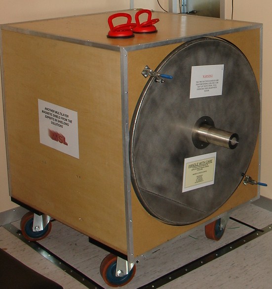
A multilayer magnetic shield box. (Photo by [Zureks] CC-BY-SA-3.0)Classic applications included shielding CRTs, tape heads, transformers, photomultipliers, and sensitive analog instruments. Put a transformer too close to the wrong part of an old television or audio amplifier and 60 Hz magnetic fields could cause very visible — or audible — trouble. The disappearance of CRTs and magnetic tape might make mu metal sound like another material destined for the antique electronics cabinet.
However, mu metal is still around. Modern applications include magnetometers, precision current sensors, electron microscopes, scientific instruments, and experiments that require extremely low magnetic fields. Commercial multi-layer mu-metal chambers are still sold for creating near-zero-field environments; with suitable construction and degaussing, some claim attenuation of static and low-frequency fields by factors approaching a million.
Quantum and cryogenic instrumentation have also created some 21st-century magnetic shielding problems. Ordinary mu metal loses performance at very low temperatures, so related nickel-iron alloys are made specifically for operation at liquid-nitrogen and liquid-helium temperatures.
Don’t Bend It
There are a couple of catches. First, mu metal gets much of its impressive permeability from its metallurgical structure. Machining, stamping, welding, or even bending it can introduce stresses and seriously degrade its magnetic properties. High-performance shields are therefore commonly formed first and then hydrogen annealed to restore their permeability.
So buying a sheet of wonderfully permeable material and folding it into a box isn’t necessarily the recipe for a wonderfully permeable box.
The second surprise is saturation. Mu metal is superb with weak fields but isn’t necessarily what you want closest to a powerful magnet. Its saturation induction is only around 0.75 tesla. In strong fields, manufacturers recommend combining it with a lower-permeability material having higher saturation capability, letting that outer layer tame the field before the mu metal handles what’s left.
History
British scientists Willoughby S. Smith and Henry J. Garnett patented mu metal in 1923 for inductive loading of submarine telegraph cables for a British company that built the Atlantic undersea telegraph cables. The seawater surrounding these cables added capacitance, requiring inductance to compensate. This was first done by wrapping the conductors with a helical wrapping of metal tape or wire of high magnetic permeability, which confined the magnetic field.
Mu-metal was invented to directly compete with permalloy, the first high-permeability alloy used for cable compensation, but it belonged to competitor Western Electric. Mu-metal was developed by adding copper to permalloy to improve ductility. Each 1.6 km of cable needed about 80 km fine mu-metal wire so there was a great demand for the alloy.
Other Tricks
Mu metal isn’t the only way to fight magnetic interference, as you can see in [FesZ’s] video below. Ordinary steel and other high-saturation magnetic alloys can redirect stronger fields. At higher frequencies, conductive copper or aluminum shields become effective through induced eddy currents. Ferrite is good at high frequencies, too, but is not very ductile nor is it very conductive. When you really need a quiet magnetic environment, active compensation coils can measure the ambient field and generate an opposing one.
But if the problem is a weak DC or low-frequency magnetic field, the basic trick hasn’t changed much. You just give the magnetic flux an easier path. Sometimes the old material in that 50-year-old television can be at home in a quantum computer, too.
The phones! They were one of the basic utilities of the 20th century, and were just about as reliable as death and taxes. Even when then power grid went down, you still had a fair shot of getting a phone call through thanks to the reliability of the Plain Old Telephone Service.
Generally, we expect our telecommunications networks to be supremely reliable. There is no moment of the day when someone doesn’t need to make a call, particularly in emergencies, and the wheels of industry and commerce depend on constant connectivity these days. Tolerance for failure is generally very thin. Despite this, and the efforts of engineers to maintain uptime at as many nines as possible, Telstra fell badly short on July 8th, 2026. The company had a nationwide outage that affected 8.8 million people, leaving them unable to make calls or connect to the network at all.
The cause of the outage would prove to be particularly embarrassing. Telstra owns and operates a highly advanced cellular network, offering 4G and 5G service across the nation’s cities and much of its outback areas. The company may outwardly appear to be a shining beacon of modern connectivity, but there was something dank lurking in the company’s server closets. Namely, three aging network time servers that had the capacity to bring the whole system to its knees.
The NTP server in question is old enough to still rock a vacuum fluorescent display, something you don’t see on a lot of modern network hardware. Credit: Microsemi
The culprit? A Microchip Technologies SSU 2000 NTP server. The model dates back to the early 2000s. Twenty four years later, Telstra still relied upon three of the units to provide network time protocol (NTP) services across its network. The servers were generally perfectly adequate in this role on any given day. That was, until the Melbourne server had a wobble.
A technician was working in the early morning to replace a backup power feed in the chassis housing the server. This caused the server to be rebooted at 3:38 AM, which normally would not be a problem. However, at some point in the last two decades or so, the server had gone through a configuration change. While it was originally intended to be a Stratum 3 NTP server, getting its time reference from a Stratum 2 unit, that process had failed at some point. It had been reconfigured instead to use its internal GPS card to gain time directly from the satellite network instead. Unfortunately, the server was also remarkably old, and suffered from a well-documented GPS date rollover bug, such that when it rebooted, it reported the time as 2006 rather than 2026.
Victoria’s V/Line train services were unable to run, as the Telstra network outage made communication across the system impossible. Credit: Thomas Hobley, CC BY-SA 4.0
The problem that stemmed from this was because time is critical to authentication. An endless cascade of devices downstream of the NTP server picked up the wrong time, and started using it to sign digital certificates and the like. This immediately caused other systems on the network to reject the spurious traffic with certificates that were 20 years out of date. The impact was swift and vast—Telstra was quickly facing a nationwide outage affecting millions of customers.
The issue was first detected at 4:20 AM. The naughty server was isolated by 7:11 AM, but it would take until 10:30 AM to identify all the network components which had received erroneous time data. It took several hours further—until 4 PM—to properly quell the NTP issues. In the meantime, a significant portion of the country had seen its phones offline all day, and entire rail networks had ground to a halt as their Telstra-based communications systems went completely offline.
Later submissions to a government inquiry would reveal Telstra had received two reminders to patch the GPS card, in 2020 and 2022. The vendor itself had issued warnings about the GPS rollover bug as early as November 2000. A decision not to fix the bug had been taken as recently as January 2026, because the undocumented change to have the server rely on GPS time was unknown, and thus the update was considered unnecessary. Simply patching the system would have prevented the issue from ever occurring in the first place.
When the outage became apparent, Telstra notified the Triple Zero Custodian, a body founded in 2025 to oversee the integrity of the emergency service. Credit: Telstra submission to government inquiry
The issue once again brought telecommunications availability in Australia to the forefront of the conversation. Repeat outages across Australian mobile networks have led to particular concerns about the ability for people to reach emergency services by calling Triple Zero from mobile handsets. The latest failure on Telstra’s behalf has led the local telecommunications industry to issue new guidance to the public on what to do when a call to Triple Zero doesn’t go through.
Modern handsets are designed to switch to a different cellular network in the case an emergency call can’t be connected—a process called emergency camp-on. However, this process takes time, and the caller will often hear silence on the line while the phone is attempting to connect. The new advice is that callers should hang up and try again straight away if their first call to Triple Zero doesn’t connect within a few seconds. On the second call, though, the phone should be given up to a minute to find another network to get the call through.
In the case of this outage, camp-on functionality worked—some 3,200 Triple Zero calls were passed to Optus and TPG networks when Telstra’s failed. However, there were some ongoing issues that saw a further 604 Triple Zero calls fail over the period to 2 PM the next day.
Overall, Telstra’s failure was a major one. It’s rare for a major network to go down so completely and over such a wide geographical area. The fact that it happened because of an undocumented change to an ancient network appliance is all the more embarrassing. It will drive home the message that documenting even seemingly minor changes is important, with the lesson likely to be told in the halls of the Australian telco for some decades to come.
Printed circuit boards were developed first for function over form. They were a way to mount components and connect them in a stable, robust fashion, while taking into regard things like packaging and cooling requirements to enable a circuit to function. Circuit boards often end up looking cool in a techy kind of way, but their aesthetic is usually very much secondary to their actual purpose.
Katrin Dietzsch likes to use her PCBs a little differently, however. She designs boards that are intended to be a narrative tool for tabletop roleplaying, and came down to Hackaday Europe 2026 to walk us through the development of this very whimsical hardware.
Roll For It
Katrin starts her talk by explaining how she came to design circuits specifically for tabletop gaming. She saw an opportunity to combine her hardware hobby with the world of TTRPGs to help maintain both hobbies amidst a busy lifestyle. She also found that hardware she built could be a great artistic medium for supporting mystery and storytelling in the tabletop world. With the right design, her circuits became very much part of the narrative themselves.
Getting to see Katrin’s PCB D20 is a highlight of the talk. It’s a great example of creative board design.
How does one create a piece that becomes special, rather than just being another art project thrown in a drawer, though? Katrin notes that meaningful objects are the ones that gather stories about them and gain emotional baggage, and thus, relevance. Interaction is also key; she relates the familiar tale that many of us have yelled at a printer before. We often anthropomorphize objects or assign them personalities just because they have some level of strange behaviour, or even if they just blink at us. Often, she’ll also start a build not from specs, but from story and the game itself. The questions asked are about how to engage players, and how to help them reach their goals, and answering those can help guide the design process.
There are also elements drawn from typical ideas around magic and artifacts that can be drawn from. For example, many tabletop roleplaying games feature the concept of attunement, where a character may have to physically and spiritually connect with an object to access its magical features. This is something that can be readily recreated in the electronic world with the use of things like capactive touch sensing. Katrin also notes that using RF can be great for creating items or puzzles that respond based on proximity, and there is all sorts of fun to be had with things like IR beams, motors, switches, or whatever else players can interact with. Code is also a beautiful place to hide secrets and easter eggs—you get to write the behaviour of the device to be as beguiling and confounding as you like.
You could use paper maps… or perhaps you could whip up a PCB with traces and solder mask and silkscreen and interactivity all woven together to create something altogether more compelling and interactive. There are grand possibilities in this space for your tabletop game to transcend the usual.
There’s also the visual side of things. It’s something that should be remarkably familiar to anyone who has been to a modern hacker or maker convention and seen the wonderful variety of badge designs created by the community. Everything from the copper layers to the silkscreen to the very routing of the fiberglass board itself can be leveraged to create an art piece that captivates and inspires. Particularly in this era when it’s so easy to find board houses that will produce your designs with soldermask in all the colors of the rainbow. Katrin’s wonderful D20 PCB serves as the perfect example of these techniques being applied well.
Like any good tabletop aficionado, Katrin has a great sense of practicality too. There’s no point designing some fantastic electronic gizmo for your game if you can’t afford the bill of materials, can’t solder the parts, or your players can’t figure out how they’re supposed to use an in-circuit programmer to interact with it. Most of us live very busy lives, so our hobby projects have to be achievable within the constraints of our lifestyle. She also notes that it’s great if you build something with longevity, rather than something that serves only as a single-use tchotchke for a one-off bit.
If you’ve ever contemplated bringing your electronics skills to bear in your role as a dungeon master, Katrin’s talk is a great place to start. Your little creations can serve as a wonderful bridge between your player’s experience and the world of imagination you’re collectively creating, and that’s always a fun time!
When I got back into SLA resin printing recently, I knew that I’d inevitably have to deal with the agony of failed prints and of course resin spills. This moment eventually came, and I felt motivated to treat mistakes as teaching moments on aspects like how to properly prepare an SLA build plate in terms of angles and supports or how to deal with failed print aftermaths.
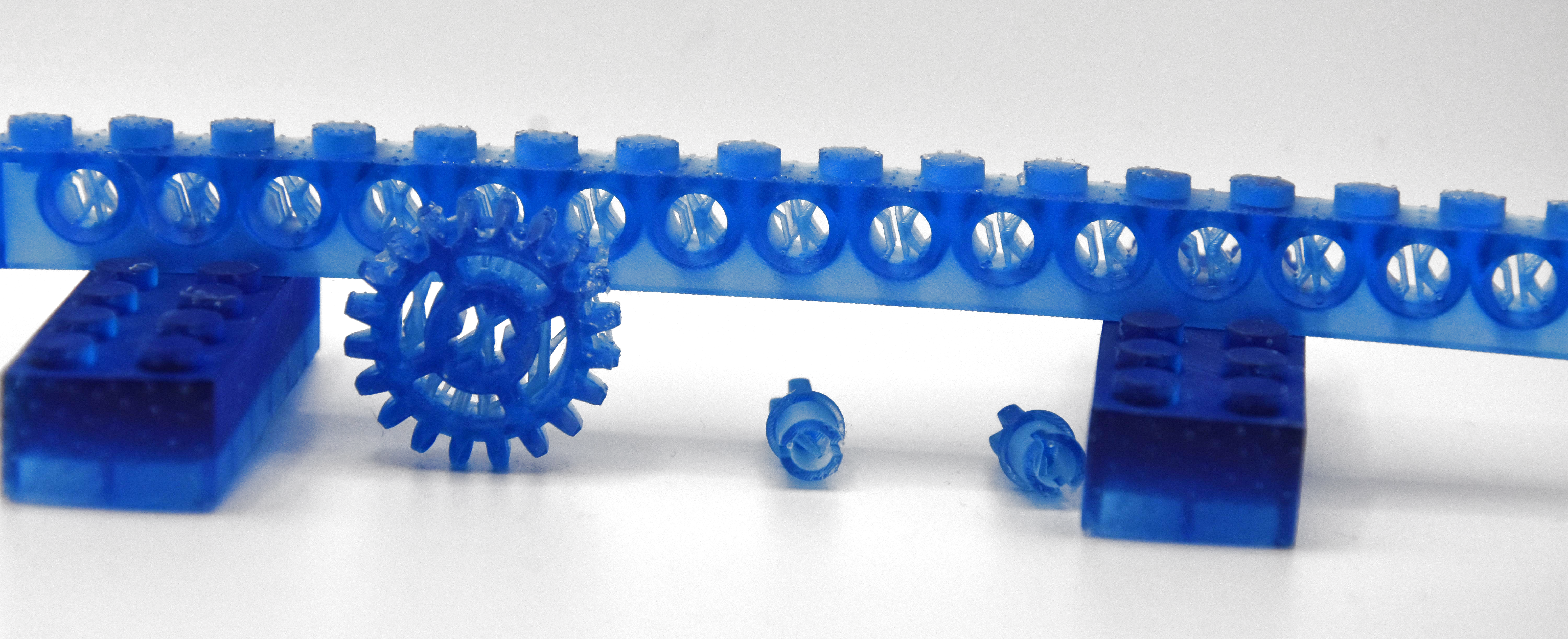
Before moving on to the disaster, I’d like to first start with a look at the resin print of the previous article, which contained a number of fairly small parts. These I had oriented and supported almost fully using the automatic methods provided by the ChituBox slicer software, and worked about 90% as I had hoped, while leaving plenty of room for improvement as well.
Overall, preparing an SLA build plate in the slicer isn’t quite the same as for an FDM printer, mostly due to one phrase that strikes fear in the heart of anyone who has ever done resin printing: “peeling forces”.
Not Bad, Not Great
For last article’s resin print, I had to put a number of models onto the build plate in the slicer, after which I mashed ‘auto arrange’, ‘auto orient’ and then ‘auto support’ in their respective tabs. I did change the orientation of the beam so that it wasn’t pointing straight upward any more, as I wasn’t going to wait a few extra hours for it to print just for that single object.
This then got me the following overview including a veritable forest of supporting structures:
You’re going to enjoy peeling off those supports later.
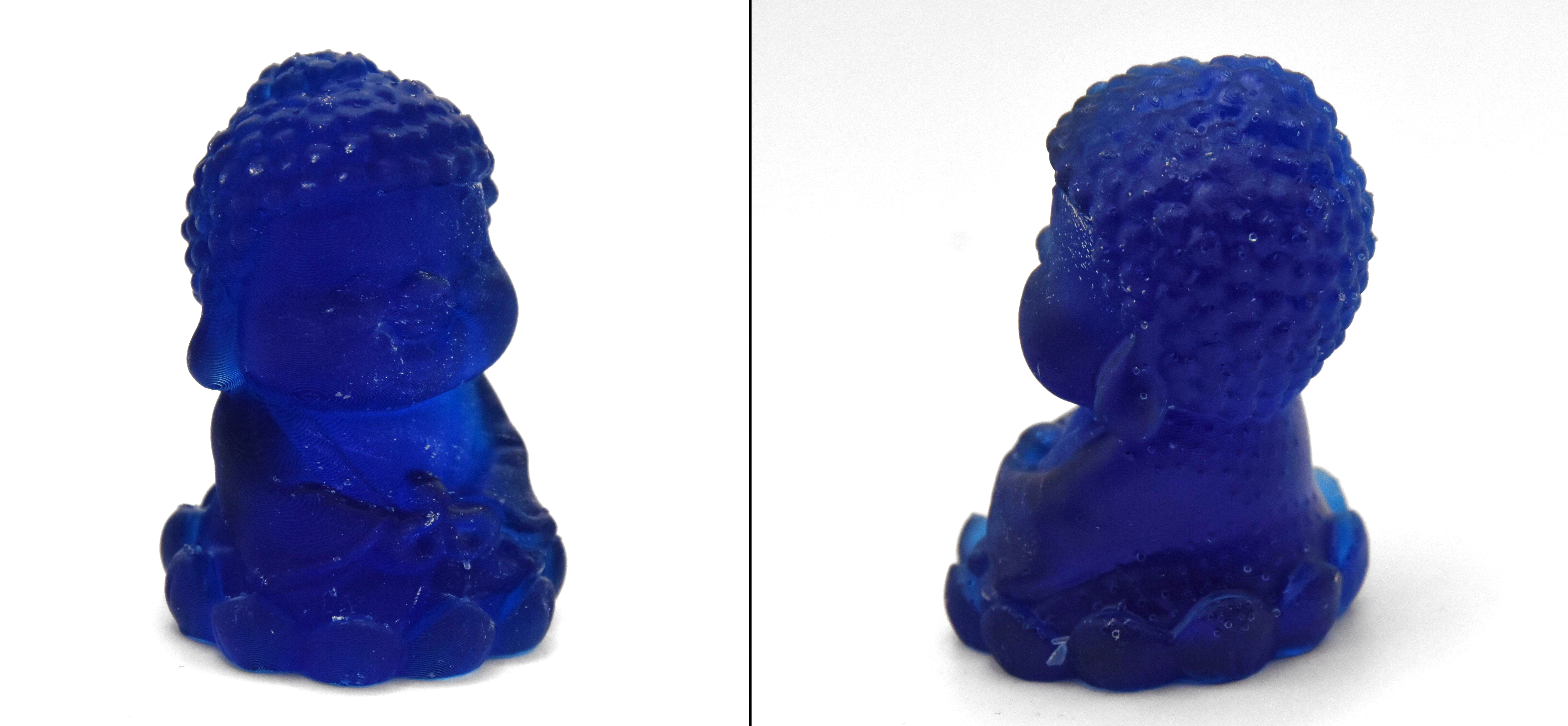
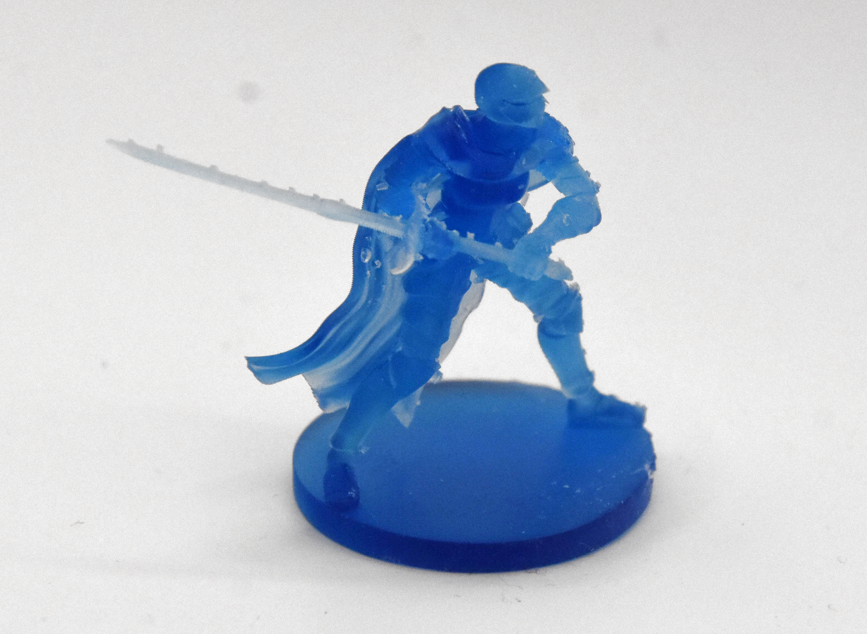
By playing it safe, I managed to get everything printed without any glitches other than my previously mentioned fight with the resin auto-feed system of the printer. Of course, by leaning heavily on defaults, I also got backstabbed by the slicer’s overzealous use of supports, especially where it was highly undesirable, such as inside parts of the LEGO Technic-compatible parts:
By rotating the figurines to be printed upside-down relative to the build plate this also meant having lots of ugly marks left by the supports, both on the happy buddha and the female knight figurine.
Here the fix seems rather straightforward: angle figurines so that supports contact things like the bottom of a surface where it won’t be as noticeable. Also inspect the auto-generated supports to remove any that are in naughty places and perhaps do some manual supporting if you feel particularly confident.
I did look at a few “how to do supports right” videos and written tutorials, and the general advice seems to be to simply forget about auto-generated supports.
For me an amazing aspect was that both figurines were angled upside-down by the slicer, when everyone prints them with the base towards to the build plate. Exactly how ChituBox’s algorithm here works is a complete mystery to me, but I reckon that this slightly confusing experience may have contributed to the subsequent disaster that occurred with another print.
Simply Bad
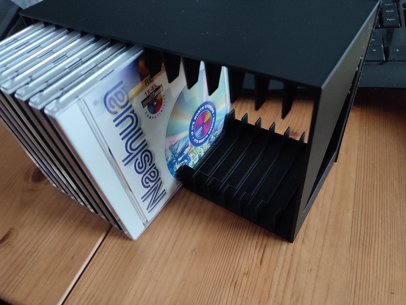
The FDM version of the CD rack in black PLA passing QA.
Where things slid sideways and wrapped themselves at high velocity around a phone pole was when trying to print a 16-slot CD rack, specifically this rather nice model by [zenitar3d] from Thingiverse. On an FDM printer this is braindead simple to print: you slap it on the build plate in the slicer, do a sanity check that it physically fits, slice it and let ‘er rip. My only issue here was that OrcaSlicer deemed it necessary to add a brim, so that took some sanding to clean up a razor sharp edge.
On the resin side of things, you enter a torment nexus: you can slap the part on the build plate, but then you risk elephant foot — a thickening at the base where exposure time is longer than for subsequent layers. Even if that’s of no concern, you still need to violently remove the part from the solid metal build plate, which is highly likely to cause damage.
If I still had the LD-002R printer with its flex plate, an aftermarket modification that I had fitted. This would be of no concern with a mere flex-and-pop, but here I’d have to violently wield a metal scraper to convince the build plate and cured layers to part ways. Clearly I need to look into flexible build plates for current SLA printers.
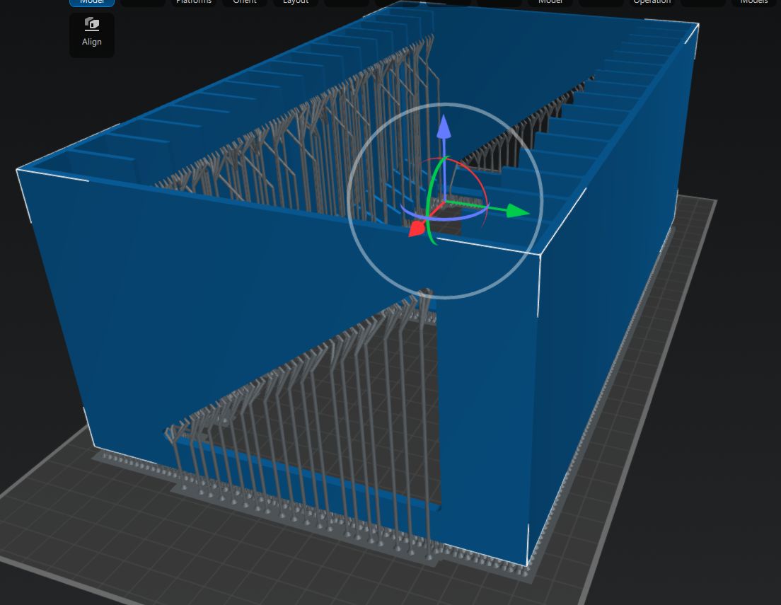
I did try to use the same auto-angle and auto-rotate approach in the slicer, but ChituBox would just always put part of the model outside of the printing area. After a while I grew tired of this and just printed it with the part slightly lifted off the build plate with medium supports like this:
Anyone who has ever done any resin printing cringes at this screenshot.
In my defense, I did this in the midst of yet another European heatwave with zero air conditioning, so maybe that had sufficiently fried my remaining brain cells. Regardless, the results were rather predictable.
Carnage
A little while later I had the good news in the sense that the supports were printing beautifully, but also bad news in that the actual model had been ripped off the supports by the aforementioned peeling forces.
Cue sad trombone SFX.
In hindsight this was obvious: the quite solid surface of the model has significantly more surface area than the area contacted by the supports. At the first attempt to peel the newly cured model layer off the nFEP (PFA) film, the tug of war resulted in the supports winning out and the print being a total failure.
You could call this the ‘FDM spaghetti’ equivalent with resin printing, where the FDM’s extruder is printing in empty air, but unlike with FDM printing the subsequent clean-up is less of a sighing, brushing away bits of thermoplastic and trying again with the glue stick, and more of a chemical hazard situation.
Dealing with an SLA resin printing failure sees you draining and filtering the resin from the vat, carefully removing any solid resin from the vat’s film and curing the failed parts so that they can be safely disposed of. All while suited up with gloves, eye protection, and at least a half-face mask with A1P2 filters that still leave you plenty of opportunity to consider whether SLA resin or IPA smells worse when the copious amounts involved of both try to overwhelm the filters.
Clean-Up Detail
All of this is perfectly fine.
Where the whole kerfuffle got even worse was when the whole auto-feeding of the resin caught up with me. After ripping the bottle out of the machine I had noticed that the GK3 Ultra had for some reason pulled a vacuum inside the bottle, which could explain some of the issues that I had experienced. This did however also mean that its internal volume had decreased due to the bottle’s deformation.
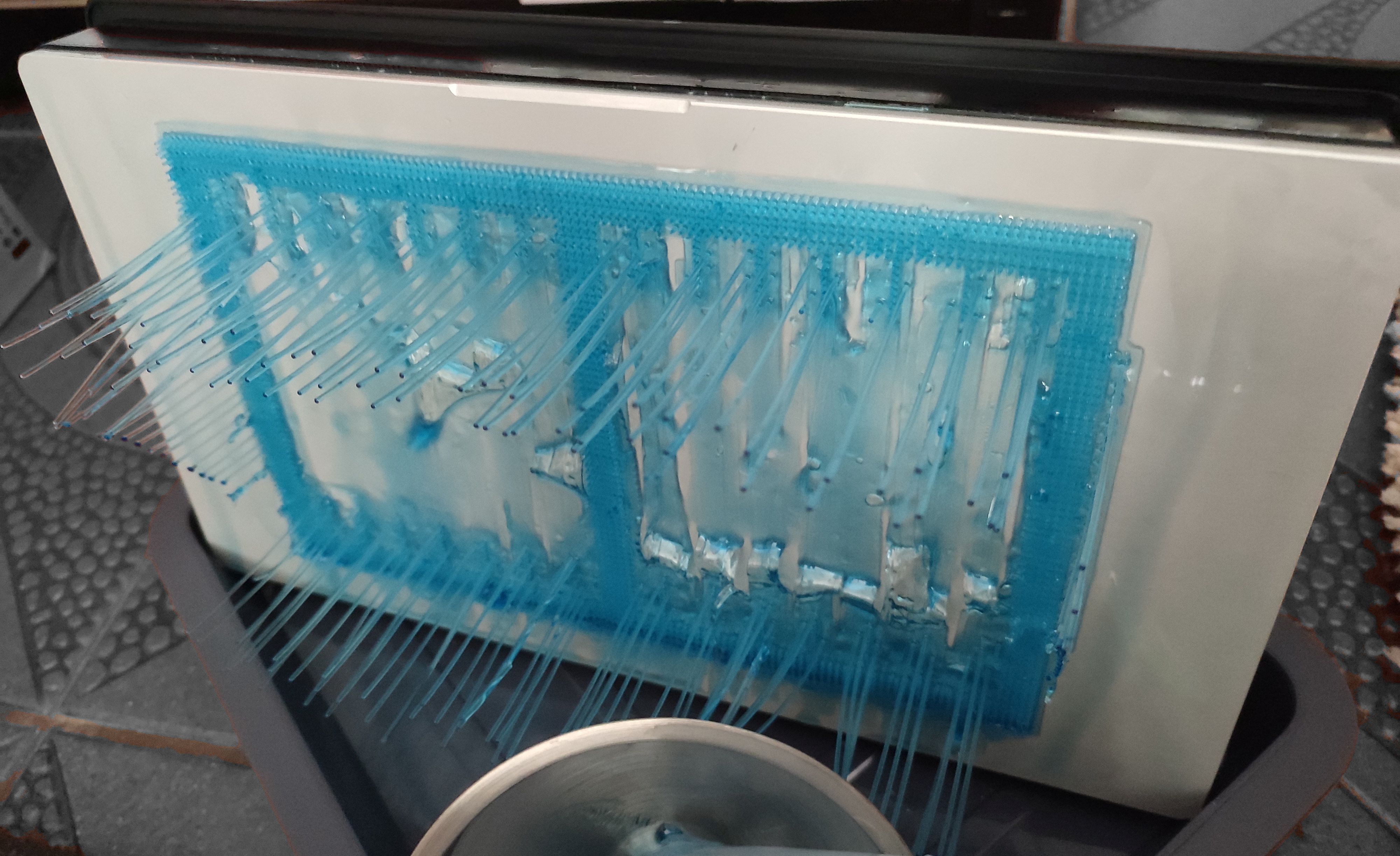
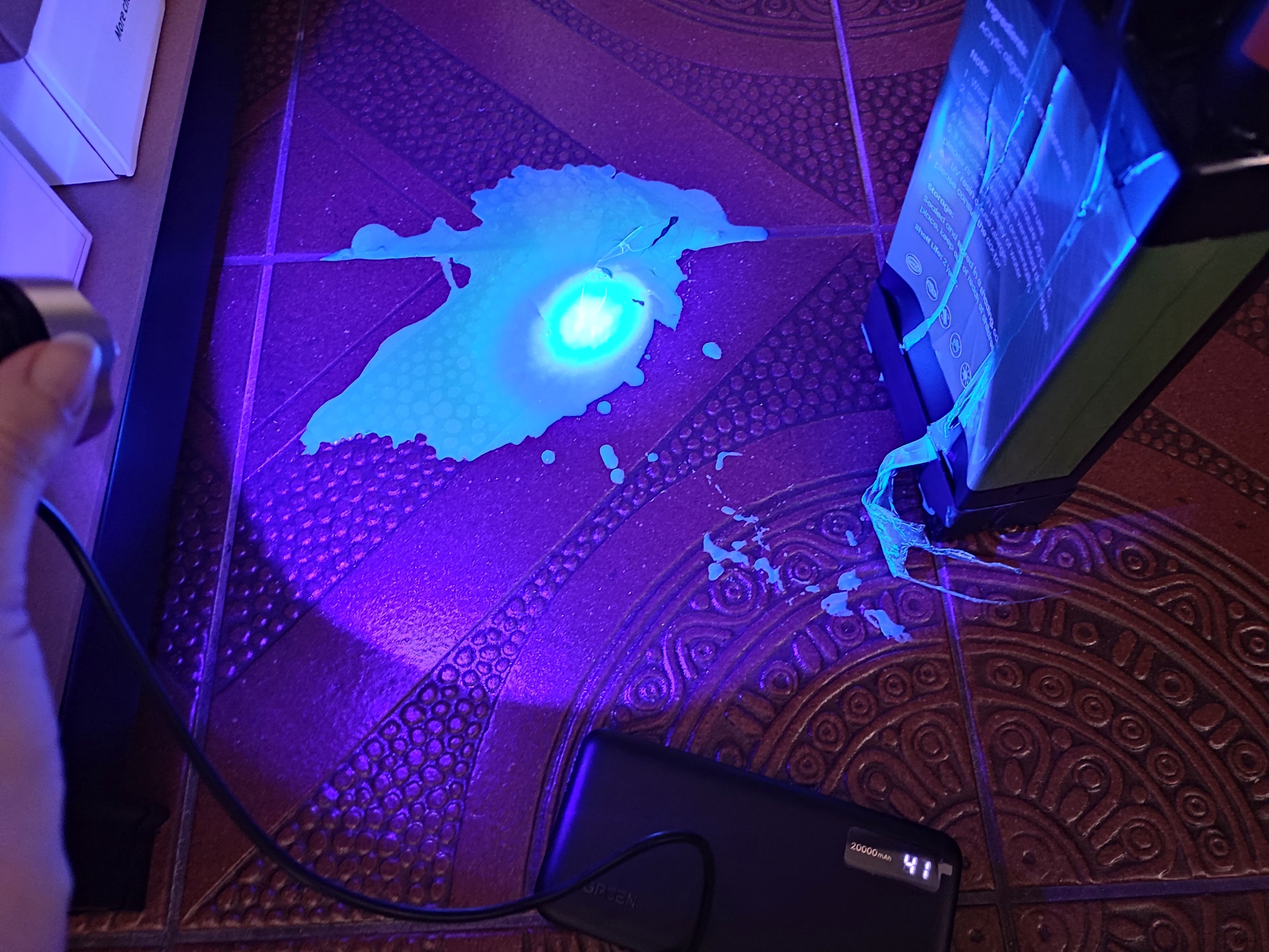
This was a detail that didn’t quite register with me until resin that I was pouring through the filter into the bottle was overflowing onto the floor. Cue copious amounts of colorful cursing and a dash for the paper kitchen towels, followed by a rather illuminating UV exposure session using a handheld UV lamp. Fortunately cured resin doesn’t bond well to tile flooring, so it can be peeled off after curing and tossed into the regular household waste. The pro-tip here is to always use silicone underneath potential resin spills. If only I had done so.
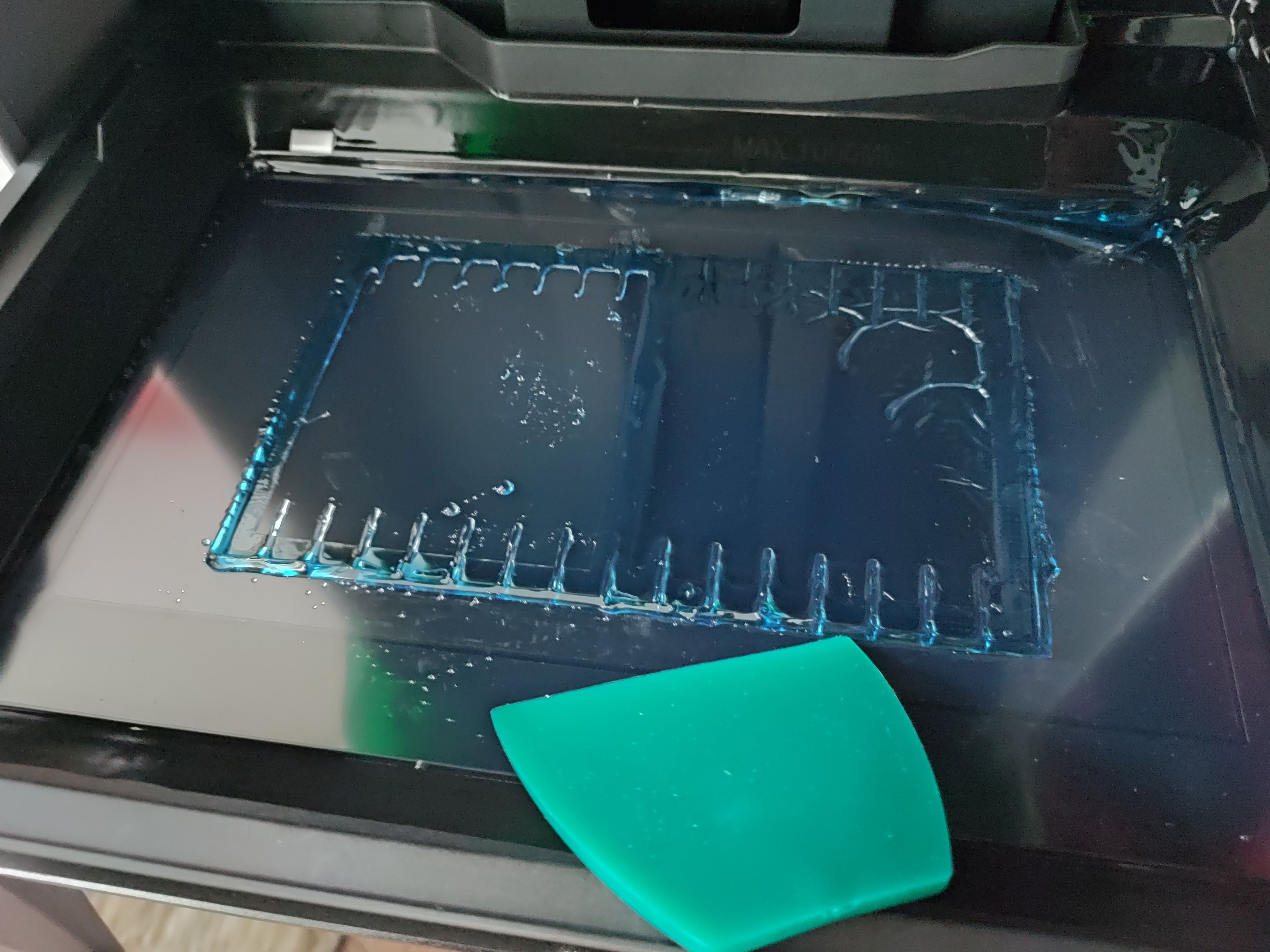
With the floor clean once more, the next challenge was to get the vat cleaned up again. The provided silicone scraper was useful here, but you absolutely need that spray bottle with IPA to soften up the connection between the PFA film and the cured resin.
This calls for IPA and elbow grease.
Using the built-in vat curing feature I could cure most of the remaining resin in the vat, but still had to use the handheld lamp to get to corners where it didn’t reach. This is the part that I’m still working on, making sure everything is clean and the PFA film undamaged before I throw myself again at another printing session.
Lessons Learned
As they say, spilled milk, or resin.
I think the primary lesson that I have learned here is that I still do not comprehend why consumer resin printers insist on having that solid lump of metal that they dare to call a ‘build plate’ — an immovable surface that you have to violently assault with a scraper after printing to make it release printed parts.
After mostly printing with the magnetically attached flex plate on the LD-002R – of course after adjusting its Z-height correspondingly – it still feels like time hasn’t moved at all here.
As a friend of mine remarked when I reported the print failure described in this article, it’s also rather astounding that there’s no simulation of peel forces in slicers to get some idea of whether your supports game is overkill or weak sauce. There are some resin printers that even try to reduce the peel forces by tilting the vat – such as the Prusa SL1S and Form 3 – and there are various ‘tricks’ to reduce the peeling forces, such as lubricating with silicone and PTFE oil, many of which I too have tried with the LD-002R with unclear results, but ultimately you just want to ‘science’ it, as the kids say.
Overall, a resin printing failure isn’t the end of the world, as long as you are mindful of a potential mismatch between the air volume in the target bottle and the resin volume in the vat you’re pouring from. Resin is only nasty until you blast it with UV, when it turns into relatively harmless plastic.
All of that said, I’m still torn on that CD rack model. Theoretically the GK3 Ultra has the build volume for it, surpassing the Neptune 4 in two directions, but it’s not easy to prepare a plate in such a way that the model isn’t ripped off its supports, is not disgraced by a massive elephant’s foot, or worst case the build plate wins and the FEP/PFA film loses the tug of war and rips.
Did I mention rips in the vat’s film? That’s another thing I experienced with the LD-002R back in the day. I was lucky that the resin spill was fairly contained, but I was puzzled for a while why the prints kept failing until I actually drained the vat.
Anyway, after all this learning, it’s time to reorganize and see what I can improve when I next hurl myself at this whole SLA resin printing topic.
Last time we found out the idea of space stations is surprisingly old. By the 1950s, everyone knew we’d be working in beautiful space stations that rotated like a wheel to give us the illusion of gravity. Of course, that didn’t happen. But we did get some practical space stations, even before the current crop. The road to get there, though, was predictably bumpy.
Convair: From TASSEL to MARS
Convair had been studying multi-person orbital stations under Krafft Ehricke since the late 1950s. One result was TASSEL, an acronym for the Three Astronaut Space System Experimental Laboratory. Proposed in 1960, TASSEL was a three-man laboratory intended for an Atlas-Centaur launch into a roughly 200-nautical-mile orbit and missions lasting two or three weeks.
Around the same time, the Air Force asked contractors for proposals for a Military Test Space Station, or MTSS. Convair was one of five companies selected for the study in 1960. The surviving record suggests that Convair’s TASSEL work fed directly into its MTSS proposal.
Then Convair did something unusual for an era overflowing with beautiful paintings of spacecraft that never existed: they built theirs. Well, sort of.
During late 1960 and early 1961, the company constructed a full-scale ground mockup called the Manned Astronomical Research Station, or MARS. The station itself was about ten feet in diameter and fourteen feet high, with two floors for working, cooking, housekeeping, and sanitary facilities. A Mercury-like reentry capsule beneath it brought the whole assembly to about 28 feet tall. You can see a contemporary video about the program below. There’s also a cache of photos and a post by [The Space Review] explaining it all.
MARS obviously wasn’t going to orbit, but that wasn’t the point. Engineers could use it to work on the less photogenic parts of putting people in orbit: life support, oxygen consumption, water regeneration, contaminant monitoring, controls, displays, and simply discovering whether people and equipment actually fit where the drawings said they would. Crews later spent as long as 30 hours inside the mockup.
Exactly where MARS fits among Convair’s various proposals is still being pieced together. Archival evidence indicates that it grew out of TASSEL and closely overlapped Convair’s submission for the Air Force MTSS program. Photographs in the San Diego Air and Space Museum archive are even identified as “MTSS/MARS.” Whatever name was on the proposal of the week, by 1961 Convair had progressed from drawing space stations to building a high-fidelity example on the ground.
Olympus and MOL
Olympus was nearly 140,000 pounds, 150 feet wide, and each arm provided 35,000 cubic feet (NASA).
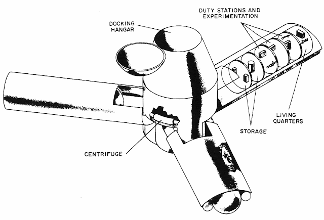
NASA wasn’t far behind. In 1962, Edward Olling at the Manned Spacecraft Center proposed Project Olympus. It would have been an 18-person station intended for launch around 1966 or 1967. It wasn’t the classic doughnut. Instead, three long arms extended from a large central hub, and rotation would provide different artificial-gravity levels at different distances from the center. The station would orbit about 300 nautical miles above Earth.
This is especially interesting because Olympus wasn’t a far-future colony study. It was being considered while Mercury was still flying. Then President Kennedy gave NASA a somewhat more pressing assignment involving the Moon.
Olympus joined the large pile of spacecraft that looked great in presentations.
The U.S. Air Force had another station that got considerably closer to hardware: the Manned Orbiting Laboratory, or MOL. Approved in 1965, MOL would have put two military astronauts into a polar-orbiting station attached to a modified Gemini spacecraft (Gemini B). Its actual classified purpose was high-resolution reconnaissance. You can see some silent footage of some of the hardware in the video below.
They selected astronauts. They built hardware. They modified a Gemini capsule with the unnerving idea of putting a hatch through its heat shield so the crew could crawl into the laboratory behind it. MOL was canceled in 1969 without a crewed station ever flying.
Meanwhile, docking — one of the basic tricks required to make stations useful — was becoming real.
Dock of the Bay
On January 16, 1969, Soyuz 4 and Soyuz 5 docked in orbit. There was no pressurized tunnel connecting them. So Yevgeny Khrunov and Aleksei Yeliseyev put on spacesuits, climbed outside Soyuz 5, traveled across the docked spacecraft, and climbed into Soyuz 4. Two spacecraft had effectively become a tiny space station, but changing rooms required going outside.
Apollo 9 flew less than two months later and provides an interesting parallel. The command module and lunar module could dock, and crews could normally transfer internally. But what if the tunnel couldn’t be used? NASA planned to demonstrate a contingency EVA transfer from the lunar module to the command module.
Rusty Schweickart was supposed to perform the exercise, but space sickness caused NASA to shorten his EVA. He tested the lunar EVA suit and portable life-support backpack from the LM porch while Dave Scott partially exited the command module, but the complete external transfer was never performed.
Salyut and Almaz
On April 19, 1971, the Soviet Union launched Salyut 1, the first actual space station. The first crew failed to dock successfully. The second crew, Soyuz 11, spent more than three weeks aboard, but all three cosmonauts died during reentry when their Soyuz depressurized. There is some video from Salyut 1, but no audio.
The Salyut name also concealed a second program. Some of the stations were civilian Salyuts, while others were military Almaz reconnaissance stations similar in purpose to MOL. Salyut 2, 3, and 5 belonged to the Almaz line, although Salyut 2 failed before a crew could arrive.
Later Salyut stations gained a second docking port. That was a huge improvement because Progress cargo ships could bring supplies and fuel while a Soyuz remained attached as the crew’s ride home. Long-duration spaceflight was becoming practical rather than heroic improvisation. Of course, none of them rotated.
Skylab
Skylab as the last crew says goodbye (NASA).
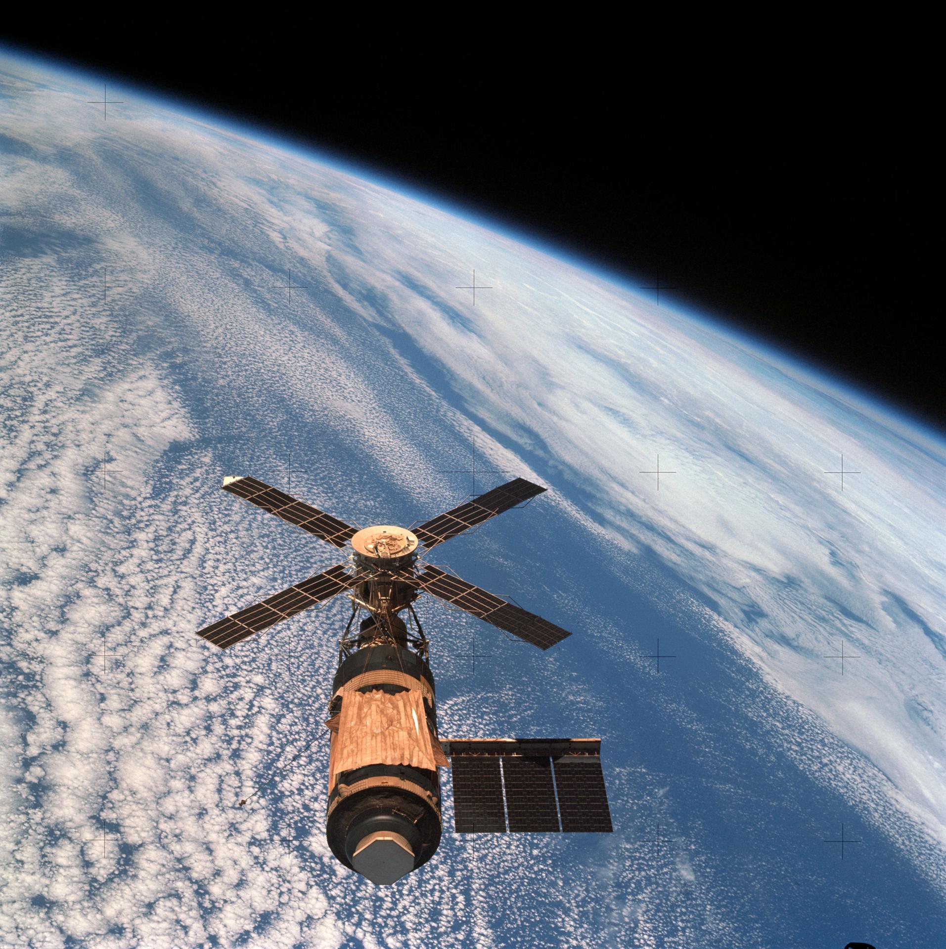
The United States took a different route. Skylab was essentially an enormous converted Saturn V upper stage. Launched in 1973, it gave its crews something previous spacecraft had lacked: room.
Three crews occupied Skylab, staying as long as 84 days. They conducted solar astronomy, Earth observations, medical studies, and experiments designed to determine what happens when human beings spend months rather than days in weightlessness. After all, why build a giant rotating station if people could simply learn to live without gravity?
Then again, we learned that long-term microgravity isn’t free. Bones, muscles, cardiovascular systems, eyes, and assorted other bits of the human body complain when they don’t have proper gravity. Still, a nonrotating station was far easier to build, so rotating wheels stayed on the drawing board.
Freedom Isn’t Free
By the 1980s, NASA was ready to try again. In his 1984 State of the Union address, President Ronald Reagan directed NASA to build a permanently occupied space station within a decade. What eventually became known as Space Station Freedom was supposed to be a large modular facility assembled by the Space Shuttle.
It would support research, Earth observation, satellite servicing, and eventually serve as a staging point for missions beyond Earth orbit.
Freedom went through redesign after redesign as costs and requirements fought each other. It did not rotate. While NASA redesigned Freedom, the Soviets quietly launched something considerably more important.
Peace In Orbit
Mir seen from STS-89 (NASA).
On February 20, 1986, the Soviet Union launched the core module of Mir.
The name means “peace,” although the Russian word can also mean “world.” Unlike the earlier Salyuts, Mir was designed from the beginning as a modular station. Additional laboratory and equipment modules arrived over the years and docked around its core.
It looked nothing like Noordung’s wheel. It looked more like somebody had been assembling an enormous machine in a garage and kept finding useful places to bolt things on.
Mir represented decades of incremental Soviet experience: Soyuz, docking, Salyut, Progress, long-duration crews, orbital repairs, and modular construction. It demonstrated that a space station could become not merely a spacecraft but a place — one that crews could maintain, modify, repair, and inhabit for months at a time.
Where’s My Wheel?
That may be the most surprising thing about the history of space stations. The rotating station wasn’t some goofy 1950s science-fiction invention. Serious engineers were proposing artificial gravity before anyone had launched anything into orbit. Oberth discussed rotating stations in 1923. Noordung drew a remarkably complete wheel station in 1929. Von Braun made the concept famous in the 1950s. NASA seriously studied rotating stations in the 1960s. The physics works.
We’ve simply never needed artificial gravity badly enough to pay the cost.
If you can tolerate microgravity, a station can be a collection of pressure vessels, trusses, solar arrays, and docking ports. If you insist on one g at a comfortable rotation rate, suddenly you are contemplating a structure hundreds or perhaps thousands of meters across.
Still, Edward Everett Hale put people aboard an artificial moon in 1869. Noordung put them aboard a rotating wheel in 1929. Kubrick had airline passengers walking around one in 1968. So after more than a century and a half of talking about space stations, I have only one question: When do I finally get my rotating space station?
People have lived in space stations for decades now, but something is wrong with them. Where are the big rotating wheels? You know the ones. They show up in old paintings of the future and, perhaps most memorably, in 2001: A Space Odyssey. Spin a great wheel in space, and people can stroll around inside with something that feels suspiciously like gravity. It seems like an obvious idea.
It is also an old idea. Much older than actual spaceflight, in fact. But to find the beginning of the space station, we have to go back to a time when powered aircraft were still several decades in the future.
A Moon Made of Bricks
In 1869, Edward Everett Hale published The Brick Moon in The Atlantic Monthly. The moon in question wasn’t natural. Hale imagined building a 200-foot-diameter sphere made from bricks and putting it into orbit as a navigation aid. Sailors could sight it and use its known orbit to determine their longitude. There was only one small problem: the thing was accidentally launched with people aboard.
That makes The Brick Moon generally regarded as not only the first fictional artificial satellite, but also the first fictional space station. Hale followed it in 1870 with Life on the Brick Moon, describing how the accidental colonists got along up there.
Hale didn’t have rockets. He proposed flinging the thing into the sky with giant flywheels, but, then again, it was 1869, so we’re inclined to cut him some slack. As the 19th century turned into the 20th, however, people started doing the math.
Konstantin Tsiolkovsky is best remembered for putting rocket flight on a sound theoretical footing. The Russian schoolteacher wrote extensively about orbital flight and space habitation, envisioning people living in orbit long before anyone had demonstrated that a liquid-fueled rocket actually worked. His ideas included rotating habitats to provide artificial gravity.
Hermann Oberth’s 1923 book Die Rakete zu den Planetenräumen — The Rocket into Planetary Space — Oberth went beyond fiction and seriously considered a permanently inhabited station. He envisioned it being periodically supplied by smaller rockets, serving as an observation and communications platform, and even acting as a jumping-off point for trips farther into space. He also suggested spinning the station to give the crew artificial gravity.
Enter The Wheel
Noordung’s space station concept from his 1929 book.
But the space station that looks like the space station in your head probably comes from a different Hermann. Herman Potočnik was an Austro-Hungarian army officer and engineer who wrote under the name Hermann Noordung. In 1929, he published Das Problem der Befahrung des Weltraums, translated by NASA many years later as The Problem of Space Travel: The Rocket Motor.
Noordung didn’t merely say, “We should have a space station.” He drew one. His station consisted of several components, but the memorable one was the Wohnrad — literally the habitation wheel. Living quarters occupied a rotating ring connected to a central hub. Rotation provided artificial gravity, while other portions of the complex could remain weightless. He considered power, communications, observing Earth, astronomy, docking, and the practical business of living in orbit. NASA calls his work one of the first detailed technical designs for a space station.
If you have seen Wernher von Braun’s famous wheel station from the 1950s, you may notice something. Von Braun certainly knew Noordung’s work — he had cited it years earlier — and the family resemblance between Noordung’s 1929 Wohnrad and the wheel station that von Braun and Willy Ley presented to American readers in Collier’s in 1952 is hard to miss. The only place we have found the articles is the reprints in Horizons, by the AIAA (start with page 46).
Whatever the exact family tree, von Braun was the man who put the wheel-shaped station into American popular culture. In 1952 he described a 250-foot-class rotating station in Collier’s, accompanied by some gorgeous Chesley Bonestell artwork. A few years later he took the idea to television with Walt Disney.
If you’ve never seen these, they are worth your time. Disney’s 1955 Man in Space and Man and the Moon let von Braun explain a remarkably detailed vision of rockets, orbital stations, and trips to the Moon to a mass television audience. A generation of kids grew up expecting this stuff. What happened?
Gravity, More Or Less
The attraction of the wheel is simple. You can’t really make gravity, at least not without bringing along a planet-sized lump of mass, but acceleration will do nicely. Stand on the inside of a rotating ring, and the floor keeps accelerating you toward the axis. In your rotating frame, it feels as though something is pushing you outward against the floor.
The acceleration is a=ω2r where (r) is the radius and (ω) is the angular velocity. Sadly, the numbers explain part of the problem.
If you want one Earth gravity at the floor, you need to either spin fast or have a large ring. For example, at 1 RPM the ring has to be 1.79 km in diameter. Speed up to 2 RPM, and you can get away with 447 meters. At 4 RPM, you are down to 112 meters.
Seems like you could just keep going faster, but there’s a problem. Four RPM doesn’t sound very fast until you are inside the thing moving your head around.
Humans can adapt to rotation, but increasing the speed makes Coriolis effects increasingly noticeable. Move your head, climb a ladder toward the hub, throw something, or even walk spinward instead of anti-spinward, and the results aren’t quite what your inner ear expects. NASA artificial-gravity studies have often used approximately four RPM as an important practical region for human tolerance, although this isn’t a hard physical limit and training matters.
There’s also a gravity gradient. Your feet are farther from the axis than your head, so they weigh slightly more. Make the radius large enough, and you won’t notice. Make the station small enough, and things get strange quickly. So bigger is better except when it comes to cost, of course.
Space Station V, still under construction. Note the window placement.
There is another oddity that movies sometimes get wrong. The outside circumference of the wheel is the floor. “Down” is away from the hub. Imagine a tire in space. You aren’t walking around on one of the flat sidewalls with the axle beside you. You are walking around the inside of the tread. So when a movie gives you a nice conventional room with a picture window on what looks like the outer wall, stop and think about where gravity ought to be pointing. Depending on the geometry, that window would probably be underfoot.
Stanley Kubrick got this wonderfully right in 2001: A Space Odyssey. Both Space Station V and the rotating centrifuge aboard Discovery make “down” follow the rotation. The famous jogging sequence works precisely because the circular wall of the set becomes the floor as the camera watches.
Next Time
Next time, I’ll look at early attempts to make a space station ranging from TASSEL, MTSS, and MARS to real Soviet and U.S. stations that had varying degrees of success. Spoiler alert: none of them are going to rotate for gravity.
Of course, people didn’t just imagine space stations. They also imagined moon bases, both fictional and actual.
Powered machinery started the industrial revolution, and it was automation that kicked it up another notch in the 20th century. The ability for machines to make things by themselves spurred increased output and in turn boosted economic growth. The concept became widely popular for manufacturers to implement, as any change with serious economic benefit tends to do. Fast forward to today, and advanced robots and fancy machine vision systems running on powerful computers are the norm in modern factories which create the many wonderful products that we all purchase, use, and enjoy.
Once upon a time, though, things weren’t so sophisticated. [Nicola Cimmino] came to Hackaday Europe 2026 to tell us all about a remarkably simple 1-bit CPU that used to run factories.
Logic, But Make It Cheap!
Nicola Cimmino used to frequent a facility that used to recycle electronic waste, which sold old bits and pieces of hardware by the kilo. Many times, Nicola would pick up odd boards with an eye to repurposing components for future projects. Eventually, one unremarkable looking chip caught his attention—the Motorola MC14500B. This chip was rather unique, being a rather simple processor with just 16 instructions and a 1-bit data bus.
The simple architecture of Motorola’s basic 1-bit chip. Credit: talk slides
It’s worth examining the era in which this chip existed. Intel dropped the 4-bit 4004 in 1971, with the famous 8-bit 8080 landing in 1974. The Zilog Z80 came along in 1976, similarly an 8-bit design. And yet, when Motorola released the MC14500 in 1977, it landed with a rather slimline 1-bit design instead. Nicola notes that this likely came down to price, since populating a chip with more transistors cost more money quite significantly back in the 1970s. If the job could be done with less, it would make the part cheaper and thus more popular in the market. Bearing this out, Nicola explains that a 1976 Zilog Z80 used 8,500 transistors and cost around $200 USD, while an MC14500 used just 500 transistors and could be had in 1977 for the bargain price of just $5 USD.
It doesn’t take much supporting hardware to get an MC14500 up and running. Notably, though, there is no memory or program counter on board, so those have to be added externally. Credit: talk slides
Back in the mid-1970s, automation in industry often consisted of simple logic that was handled by cabinets full of relays. This took plenty of bulk, required hard-wiring everything, and also involved plenty of electromechanical parts that could wear out. Changing logic required manually rewiring things which could be fussy and tedious at the best of times. In those days, the Programmable Logic Controller was just coming into use, developed to be a reprogrammable system for industrial automation tasks that was more flexible and reconfigurable just by reprogramming it.
The MC14500 sprung up as a useful tool at this time, powering a great many programable industrial systems. It was designed to offer the bare minimum requirements for its application, while leaving extraneous hardware for designers to implement if and when it was needed. The architecture is simple enough for Nicola to explain with a single slide. The chip came with a 1-bit logic unit, operating with a result register, a 1-bit accumulator and the data bus. A minimal system could be lashed up with the MC14500, a counter, some external RAM or ROM (since none was onboard), and an input decoder and output latch of 8 bits each. This setup would only allow for doing combinational logic, since there is nowhere to store the current state of the system. However, hooking some outputs back to the inputs could allow for sequential logic, since it would allow for storing the current state of the system via those outputs. Nicola then steps through various other configurational changes to addressing and system architecture that could be made to optimize the MC14500 for use in different ways.
Nicola built a homebrew MC14500 system, allowing him to get to grips with the classic chip. Credit: talk slidesA more polished version came later, built on a custom PCB. Credit: talk slides
If you wanted to get to grips with using an MC14500 in industrial contexts, you would do well to pay attention to this talk, even if it came out some 40 years past the part’s heyday. Beyond the basic system architecture, Nicola explains how to use the limited instruction set, and how to get such a system executing simple programs in ladder logic, which remains somewhat of an industrial standard to this day. Beyond that, he steps up to more complex logic, like if/else conditionals and the use of some of the weirder instructions of the chip. He then shows off the hardware he built himself—both a breadboarded MC14500 setup built with wirewrap, and a more polished version on a custom PCB.
It’s not every day you get to learn about the nitty-gritty details of working with industrial hardware from the ground up. And yet, that’s exactly what Nicola brought to Hackaday Europe 2026. It’s an excellent primer on the topic, and also simply just good fun if you’re a fan of electronics and logic itself!
These days open source is everywhere, and frankly, we couldn’t be happier about it. But even with as prevalent as open software and hardware has become, we still occasionally hear about a project that takes the concept somewhere unexpected. Which is precisely why we were so eager to hear more about the fascinating work [Phil Underwood] has been doing.
In his talk Open Source Caving: 20 Years of Making Cave Mapping Tools at Hackaday Europe 2026, [Phil] takes us through a series of progressively more advanced open hardware devices that he’s designed to increase the speed and accuracy of underground mapping efforts. Along the way, he’s learned a number of valuable lessons about designing hardware that’s robust enough to handle the uniquely challenging environment underground while still being accessible enough for a hobbyist to build and use.
Improving on the Old School
It’s not much of a stretch to assume that most Hackaday readers haven’t spent a lot of time crawling through underground passages, and as such, may not be immediately aware of how one begins to map a cave in the first place. Helpfully [Phil] starts off his talk by explaining the traditional process — which generally involves a compass, an inclinometer, a tape measure, and plenty of intricate notes.
Once you’ve collected all that data and successfully returned to the surface with it, you can plug it into software and create a three dimensional map of the cave. Sprinkle in some surface topography, and you’ve got a pretty slick overview of whats above and below ground.
Like so many other cavers, [Phil] wanted a way to make that first half of the process a bit less tedious. He imagined an electronic device that could take at least some of the necessary measurements for him, but was limited by the technology and at-home production capabilities available to hobbyists in the early 2000s. There was also the cave environment to contend with: any piece of equipment used in a cave not only needs to be able to handle the dusty and cramped conditions, but must be reasonable shock resistant. If that wasn’t tricky enough, there’s also a non-zero chance that it will need to spend some amount of time underwater.
Incremental Improvements
The first-generation of [Phil]’s surveying device. Undaunted, [Phil] put his first electronic caving aid together in 2008. Inside the off-the-shelf Radio Shack enclosure was an 8-bit PIC18LF2550, a dot-matrix display, an accelerometer, and a magnetometer. The data from the two sensors could be used to determine the heading and angle that the device was being held at, and while it still required the operator to manually take a distance measurement along that vector, having two-thirds of the information already computed saved considerable time and effort during surveys.
The first-generation of [Phil]’s surveying device.The next big technological leap came in 2020 — not just in terms of the device itself, but in the tools [Phil] had access to. This new device utilized a 32-bit microcontroller, a 3D printed frame, and included a laser rangefinder.
Thanks to the the increased computational capabilities offered by the modern MCU, more of the necessary calculations could be done on the device itself, which further sped up the surveying process. But [Phil] notes that the data from the laser module wasn’t always reliable, and keeping the more complex device protected from the elements introduced new challenges.
Now evolving at a faster clip, by 2023 [Phil] had improved on the design with a better integrated 3D printed case, custom silicone buttons, and a more polished user interface. At this point, he also switched over to writing the device’s firmware in CircuitPython. The lower bar of entry compared to C seemed to better resonate with those in the community, and consequently [Phil] started seeing more code contributions from outsiders.
New Dimension, New Challenges
By this point [Phil] had a pretty solid handheld device to assist in performing cave surveys, but the end result was ultimately the same as if the measurements had been taken manually. Each successive generation of the hardware made the process of gathering spatial data faster and less cumbersome, but didn’t meaningfully improve the final product.
Creating higher fidelity maps would require more data and the computational power to churn through it, which is why the latest generation of [Phil]’s hardware utilizes a Raspberry Pi 5 Compute Module and a pair of low-light cameras to perform photogrammetry. When combined with the heading and angle data, this produces a textured 3D model of the inside of the cave with minimal manual effort on the part of the user.
While this latest generation of hardware is undeniably more capable than what came before it, there’s an argument to be made that it also takes a step backwards in some respects. The cameras represent a physical weak point, and [Phil] says he’s still working on an approach to more adequately handle the increased power requirements of the Pi 5 Compute Module compared to the microcontrollers used in his earlier devices. But just as with the rest of the problems faced over the last two decades, these issues will likely be resolved in time as well.
In the end, this incremental approach to hardware development may be the most valuable lesson to take away from [Phil Underwood]’s talk. It’s a safe bet that the vast majority of those who view this presentation will never find themselves exploring an underground cave system, much less mapping one. But that doesn’t mean they can’t learn from his practical and methodical approach to building the right tool for the job.

 Login
Login