[Bas BotBerg] wanted to use a portable Bluetooth thermal printer to run off reports on sensor data collected by an ESP32-C3 microcontroller. But as is so often the case these days, the only official way to interface with the printer was through a proprietary smartphone application provided by the manufacturer. With no documentation on how the thing works, he set out to reverse engineer the printer’s communications protocol so he could control it from the MCU — but the route he took to get there was a bit different than what we usually see, and is an excellent case study for those who might have similar projects in mind.
The standard procedure for something like this, if it can be called that, is to use Android’s built-in debugging capability to log Bluetooth communications while running the manufacturer’s application. The resulting file can be fed into Wireshark, and with patience and some educated guesses, you can usually work out the various commands and values that get passed to the hardware.
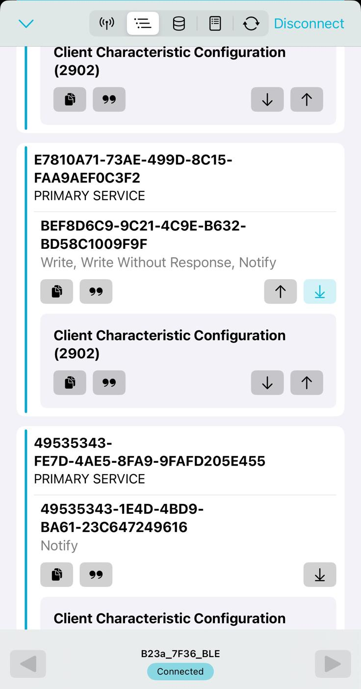
But in this case, [Bas BotBerg] ignored the manufacturer’s software and instead used an application that can query a device and list its Bluetooth Low Energy services and characteristics. Specifically, he looks for services that are marked as writable, and starts pushing data into them to see how the printer responds. For this he uses Python with the Bleak library, as it allows him to rapidly iterate and adapt his code. After a bit of poking and experimentation, he finds the proper incantation to get the printer’s motor to kick on an advance the paper — a critical first milestone that tells him he’s on the right path.
Once [Bas BotBerg] mapped out what data needed to be sent to what endpoints to operate the printer in Python, it was a relatively straightforward process to send those same payloads using C++ code on the ESP32. For extra style points he also brought in the Adafruit GFX library so he could produce icons and more easily format the output of the printer.
Being able to monitor voltages and currents is essential for many applications, with the national electrical grid being no exception. The obvious complication here is that the voltages and currents are massively higher than for those other applications, making safely monitoring these somewhat of an engineering challenge. The used systems for current monitoring are detailed by [Jordan Taylor], also known as [The Electric Brit], in an explainer of grid-level current transformers (CTs) and associated elements that help to provide galvanic isolation for safe current measurements.
Even if the basic principles remain the same, when you’re dealing with currents of 5 kA and more, the associated clearances and penalties for getting a detail wrong increasingly correspondingly. The CTs help to implement over-current protection (OCP), over-voltage protection (OVP) as well as differential protection, which is useful to detect leakage and shorts, which could also happen inside the CT if the windings become damaged.
Any such failure condition can trigger a circuit breaker to be tripped, or other corrective measures to be taken. Incidentally this also how it can be detected when someone is tapping off power in an illicit manner. As with all transformers they’re never perfect due to issues like core saturation, and thus performing accurate measurements and picking the right type of transformer is an art in itself, as explained in the video.
Ultimately CTs and the associated equipment are what makes an AC power grid responsive to any changes and with it into the reliable foundation of modern-day society.
If you’re in motorsport, or maritime, or mining fields, you can always call on a technician to come down and fix something when it’s broken. You can lay hands on the parts, reconfigure things, make repairs, and get something working again. In space, that’s seldom possible. If you’re lucky enough to have a manned mission, you might be able to make some running repairs; if you’re working with an unmanned robot, probe, or satellite, your potions are altogether more limited. If you can’t find a fix, it’s game over—a particularly brutal result when huge budgets and years of work are on the line.
Janelle Wellons came down to Hackaday Europe to talk about space. More particularly, the engineering and debugging operations that keep all sorts of space programs alive. Her talk dives into some of the creative solutions engineers have had to come up with to save million-dollar missions from becoming unrecoverable boondoggles.
Janelle came down to Hackaday Europe to talk about space, because she lives and breathes it. An experienced aerospace engineer, she’s worked at NASA JPL and iSpace, contributing to the success of missions taking place far from our humble globe. She drew on that experience to talk through what it takes to keep a mission on the rails when things go a little sideways, which happens in space, just as it does anywhere else.
Galileo was supposed to have a powerful high-bandwidth link back to Earth. When the antenna failed to deploy, NASA engineers had to get creative to find a solution, as Janelle explains in her talk. Credit: talk slides
A fantastic example of that, retold in her talk, is the Galileo mission. It was built to travel far across the solar system, eventually winding up at Jupiter to study the Red Giant and its moons. The probe was engineered with a pair of communication systems—a low-gain antenna for vital signs and management, and a high-gain antenna for sending science data and images back to Earth. The high-gain antenna was key to the mission, capable of offering 10,000 times the bandwidth of the low-gain antenna.
Tragically, though, the high-gain antenna never got to play its starring role. It didn’t deploy properly after launch, and that left NASA with a probe capable of capturing all this fantastic science data, but no way to send it home at a reasonable data rate. Janelle steps through the multiple hacks that make the most of the communication link with the low-gain antenna. NASA engineers whipped up compression algorithms for images and science data, and figured out how to array several Deep Space Network antennas for better signal. This netted an effective data transfer rate of 1,000 bits/second with the low gain antenna. It was still a far cry from the 134 kilobits per second that should have been possible with the high-gain antenna, but a huge leap forward from the 8-16 bits originally possible with the low-gain rig. Ultimately, it saved the mission, allowing the capture of mountains of scientific data on the largest planet in the solar system.
“NASA Astronaut Christina Cook is also working through troubleshooting steps of the waste management system that’s aboard the Integrity spacecraft.” – Ground control, Artemis II mission, 2026
Left—the Artemis II toilet, a leap forward in space-based waste management technology. When it’s working, anyway. Right—the collapsible contingency urinals (CCU) used to capture and store liquid waste when the Artemis II’s main toilet was out of order. Credit: talk slides
Another great story told by Janelle concerned the Artemis II mission. The lunar flyby was part of NASA’s efforts to eventually return to the Moon itself, and was notable for debuting some special new hardware—the toilet. Unlike previous visits to the moon as part of the Apollo program, Artemis astronauts travel in luxury, with a proper commode built to handle the specific requirements of the zero-gravity space environment. Unfortunately, though, this new hardware had plenty of teething problems.
Early attempts to repair the system involved attempting to reprime the toilet’s pump by adding water to the system. It wasn’t long before the toilet threw another error, though. On the short-duration Artemis II mission, the toilet was set up to vent urine to space. Only, venting wasn’t working—with the suspicion being that the vent pipes had frozen over. The trick to solve this was simple—turning the spacecraft to face the vents towards the sun, so as to heat them enough to melt the blockage. Janelle also notes that during the multiple periods the toilet was down, the astronauts had to rely on alternative means of passing waste—showing a slide of the “collapsible contingency urinals” that did the job.
Janelle’s selfie, taken with the Perseverance twin rover at NASA JPL. Credit: Talk slides
There’s also a great look at Perseverance’s twin, which lives here on Earth. Janelle has been down to the Mars yard at NASA’s Jet Propulsion Laboratory, where engineers, in her words—”test before you do.” The problem is, when you’re driving a robot on a foreign planet, you can’t just send someone over to repair a broken wheel or flip it back up if it tips over. Thus, many maneuvers and operations are rehearsed in the Mars yard with the twin of Perseverance, running it over recreated obstacles to determine a safe plan of attack.
It is a classic Hackaday situation. You have an Egret GT E-scooter. It has a screen that shows the usual dash stats, but that led to an annoyance. You could accidentally enter firmware update mode and, from there, enter operational mode without the security PIN. [Ben] couldn’t let that stand, so he reverse-engineered the protocol and rewrote the firmware in Rust. As he put it, “… because I have to break… everything I own…” We get it.
The mobile app was useful for some basic info, since sniffing Bluetooth is fairly easy and analyzing mobile code is, more or less, straightforward. Analysis revealed some data that doesn’t show on the display and that several things are sent back to home base tagged with the scooter’s unique ID — another reason to gut the existing firmware.
Internally, the scooter uses the CAN Bus, so out came the oscilloscope and a homebrew CAN decoder. Surprisingly, the CAN bus is accessible on the USB-C port’s data pins. Officially, the port is only for charging phones, so you have to wonder what your phone makes of the alien signals on the data pins when it is charging.
Firmware updates actually come in at least three flavors: display, input panel, and main controller. Reverse engineering the firmware update process was crucial to installing the new firmware.
If you own a similar scooter, this post is a goldmine. If you don’t, it is still a very detailed breakdown of a reverse-engineering workflow, and you can apply many of the tools and techniques to your next project.
Of course, another option is to just keep the scooter and replace the brains. If you want to learn more about reverse engineering, there are literally dozens of Hackaday posts to help you get started.
During his continuing analysis of the architecture and microcode of Intel’s highly influential 8087 floating point unit (FPU) co-processor, [Ken Shirriff] has now arrived at the point where he can put together how the 8087’s microcode implements various x87 instructions. One of these, the FSCALE instruction turned out to be far more complicated than assumed, with one might assume to be a straightforward powers-of-two scaling turning out to entail over 140 micro-instructions and three levels of sub-routine calls just to handle all cases.
The annotated die shot in the heading image shows the functional blocks that are used by this one x87 instruction, to give some kind of idea of what amount of hardware even ‘just’ scaling a floating point number involves.
Much like with the x86’s CISC-style ISA, these 8087 instructions break down into individual steps that involve everything from loading values into registers, performing operations, checking for and handling error conditions as well as stack management. As can be seen in [Ken]’s breakdown of the FSCALE implementation in the 8087 it’s all very logical, taking a high-level instruction and doing all that’s needed for a robust implementation, without bothering the developer with the details.
Of note is that the 8087’s implementations led to the IEEE 754 floating point standard, providing what definitely at the time was one of the most mathematically accurate FPUs that somehow still was financially responsible enough to make it into a relatively affordable PC.
The Philips PM5139 is not famous. It won no great victories on the battlefield, nor was instrumental in changing the political landscape. It was just a useful function generator that you might find on a workbench somewhere, doing its job quietly and relatively accurately. [doctormord] has been doing the work to reverse engineer this humble piece of hardware.
The PM5139 is poorly documented; the only existing service manual out there is for the PM5138A, a less-capable sister model. Hence, there was some value in reverse engineering the device to understand it better. Work started with two EPROM dumps capturing what Philips put in the box all the way back in the early 1990s. From there, the code was examined and tinkered with until [doctormord] felt confident to modify it and improve upon what was already there. This was achieved with the aid of an 8051 emulator that could run the code to make it obvious what was going on. The result was a custom “V2.0” firmware that adds six arbitrary waveforms to the function generator and the ability to play simple music, amongst other tweaks.
The NEC V20 is an Intel 8088-compatible processor that features the same use of microcode, though with its own characteristics. This makes it important to use this same microcode if your goal is to create a cycle-accurate emulator of this processor, as [GloriousCow]’s goal is. Cue decoding the microcode ROM in a die shot of this CPU, in order to create a usable ROM image.
As with any fabricated ROM you can technically do it by hand, the ROM section in the die shot contained 29,928 bits which even at a pretty zippy pace would take up a considerable amount of time to parse. Here you can divide-and-conquer by handing parts of the ROM off to good friends, or you can use automation and some machine vision and theoretically get an answer as soon as you have finished writing and testing the tool.
Close-up of some of the microcode bits.
Although [Travis Goodspeed]’s MaskRomTool exists exactly to automate bit detection, it was found that there wasn’t enough contrast in the die shot for it to work reliably. What it did provide were the locations of the bits and from it 42×42 pixel PNG files of each bit.
Next a convolutional neural network (CNN) was trained to determine the difference between a 0 and 1 bit. This still took the manual classifying of 1,000 images, but seemed to work fairly well. Although some bits were marked as ambiguous, it was easy enough to use Mark 1 eyeballs to run a classification on these handful of images than to tweak the CNN model.
With this microcode in hand it was then possible to match it against the V20’s internal architecture to fully determine what each part does. Although not quite finished yet, there’s a GitHub repository containing the progress so far.
The V20’s microcode has been the focal point of much legal fighting back when NEC and Intel were still duking it out in how far one could make a CPU compatible with that of a competitor.
Resin 3D printing has opened up a whole new scale of resolution for hackers, but the technology can go still finer; commercial micro-SLA and two-photon polymerization printers can print items with sub-micron feature sizes, but the machines are well out of reach for hackers. There’s more than one way to get such high resolution, though, as [Diffraction Limited] demonstrated with his micron-scale resin printer.
The printer builds on [Diffraction Limited]’s previous micro-manipulator and fiber-coupled laser. The micro-manipulator holds the end of the optical fiber just in front of the build plate, which is coated with resin. A 405-nm laser shines through the fiber, curing the resin in a narrow cone in front of the fiber’s core, which the micro-manipulator can trace in a pattern to build up objects, much like an FDM printer. Since the fiber’s inner core is only three microns across, the cured resin shears cleanly away from it when the fiber moves. Since the principle is so similar to an FDM printer, a standard slicer could be used to generate the tool paths.
Early testing proved that the principle worked, but the resin wasn’t absorbent enough for very high resolutions; UV light passed through previously cured resin too easily, limiting the minimum layer height. A UV-absorbent dye dissolved in the resin solves this by limiting the light’s penetration depth. [Diffraction Limited] found that curcumin, the natural dye responsible for turmeric’s bright yellow colour, worked well for this; as an added bonus, alcohol easily extracts it from turmeric powder. This solved the resolution issues well enough for [Diffraction Limited] to print a series of Benchies 150 µm long, a Stanford bunny dwarfed by a human hair, and a few other microscopic pieces. Conveniently, the curcumin dye leaves the printed objects slightly fluorescent under UV light, making them easier to pick up under a microscope.
If you tear into old TVs or recording equipment, you may see shields made from some exotic-looking metal. Old timers will tell you it’s called mu metal, and its purpose is to — sort of — shield things from magnetic fields. The qualification is important. Unlike a conductive RF shield, mu metal doesn’t really stop a magnetic field. Instead, it gives magnetic flux an easier path to follow around whatever you’re trying to protect.
What’s In The Metal?
Mu metal belongs to a family of soft magnetic nickel-iron alloys. A typical modern formulation is about 80% nickel and 15% iron, with molybdenum and a few other elements making up most of the remainder. What makes it useful is its extremely high magnetic permeability. Commercial material can have relative permeability around 100,000 or more, and some specialty alloys can reach even higher.
You can think about reluctance as the magnetic equivalent of resistance. Put a high-permeability shell around something sensitive, and magnetic flux would much rather travel through the shell than through the space inside it, just like current tends to take the path of least resistance.
This works particularly well for DC and low-frequency fields, exactly where your usual copper or aluminum EMI shield isn’t much help.
You May Have Seen It Before
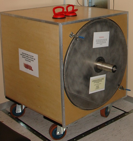
A multilayer magnetic shield box. (Photo by [Zureks] CC-BY-SA-3.0)Classic applications included shielding CRTs, tape heads, transformers, photomultipliers, and sensitive analog instruments. Put a transformer too close to the wrong part of an old television or audio amplifier and 60 Hz magnetic fields could cause very visible — or audible — trouble. The disappearance of CRTs and magnetic tape might make mu metal sound like another material destined for the antique electronics cabinet.
However, mu metal is still around. Modern applications include magnetometers, precision current sensors, electron microscopes, scientific instruments, and experiments that require extremely low magnetic fields. Commercial multi-layer mu-metal chambers are still sold for creating near-zero-field environments; with suitable construction and degaussing, some claim attenuation of static and low-frequency fields by factors approaching a million.
Quantum and cryogenic instrumentation have also created some 21st-century magnetic shielding problems. Ordinary mu metal loses performance at very low temperatures, so related nickel-iron alloys are made specifically for operation at liquid-nitrogen and liquid-helium temperatures.
Don’t Bend It
There are a couple of catches. First, mu metal gets much of its impressive permeability from its metallurgical structure. Machining, stamping, welding, or even bending it can introduce stresses and seriously degrade its magnetic properties. High-performance shields are therefore commonly formed first and then hydrogen annealed to restore their permeability.
So buying a sheet of wonderfully permeable material and folding it into a box isn’t necessarily the recipe for a wonderfully permeable box.
The second surprise is saturation. Mu metal is superb with weak fields but isn’t necessarily what you want closest to a powerful magnet. Its saturation induction is only around 0.75 tesla. In strong fields, manufacturers recommend combining it with a lower-permeability material having higher saturation capability, letting that outer layer tame the field before the mu metal handles what’s left.
History
British scientists Willoughby S. Smith and Henry J. Garnett patented mu metal in 1923 for inductive loading of submarine telegraph cables for a British company that built the Atlantic undersea telegraph cables. The seawater surrounding these cables added capacitance, requiring inductance to compensate. This was first done by wrapping the conductors with a helical wrapping of metal tape or wire of high magnetic permeability, which confined the magnetic field.
Mu-metal was invented to directly compete with permalloy, the first high-permeability alloy used for cable compensation, but it belonged to competitor Western Electric. Mu-metal was developed by adding copper to permalloy to improve ductility. Each 1.6 km of cable needed about 80 km fine mu-metal wire so there was a great demand for the alloy.
Other Tricks
Mu metal isn’t the only way to fight magnetic interference, as you can see in [FesZ’s] video below. Ordinary steel and other high-saturation magnetic alloys can redirect stronger fields. At higher frequencies, conductive copper or aluminum shields become effective through induced eddy currents. Ferrite is good at high frequencies, too, but is not very ductile nor is it very conductive. When you really need a quiet magnetic environment, active compensation coils can measure the ambient field and generate an opposing one.
But if the problem is a weak DC or low-frequency magnetic field, the basic trick hasn’t changed much. You just give the magnetic flux an easier path. Sometimes the old material in that 50-year-old television can be at home in a quantum computer, too.
Needing less than 70 grams of filament, [Chefkoch]’s 3D printed PCB vise solder station might be a good way to use up some filament spool leftovers and get yourself a handy tool in return.
What we like about this design is that it is multi-functional, and cleverly uses the solder spool as a counterweight to add stability that might otherwise be lacking in such a compact design.
The assembly can be reconfigured so that the jaws are either horizontal or vertical; the solder spool is held conveniently either way. The whole thing is 3D printed, so there’s no other hardware or fasteners involved. It’s probably best suited to small boards, but it’s also compact, entirely 3D printed, and doesn’t need much filament.
Still have some filament left over and want a nifty solder feeder to go with it? Check out the solder scroll, a pen-like DIY tool that makes handheld solder feeding a little less of a hassle.
The phones! They were one of the basic utilities of the 20th century, and were just about as reliable as death and taxes. Even when then power grid went down, you still had a fair shot of getting a phone call through thanks to the reliability of the Plain Old Telephone Service.
Generally, we expect our telecommunications networks to be supremely reliable. There is no moment of the day when someone doesn’t need to make a call, particularly in emergencies, and the wheels of industry and commerce depend on constant connectivity these days. Tolerance for failure is generally very thin. Despite this, and the efforts of engineers to maintain uptime at as many nines as possible, Telstra fell badly short on July 8th, 2026. The company had a nationwide outage that affected 8.8 million people, leaving them unable to make calls or connect to the network at all.
The cause of the outage would prove to be particularly embarrassing. Telstra owns and operates a highly advanced cellular network, offering 4G and 5G service across the nation’s cities and much of its outback areas. The company may outwardly appear to be a shining beacon of modern connectivity, but there was something dank lurking in the company’s server closets. Namely, three aging network time servers that had the capacity to bring the whole system to its knees.
The NTP server in question is old enough to still rock a vacuum fluorescent display, something you don’t see on a lot of modern network hardware. Credit: Microsemi
The culprit? A Microchip Technologies SSU 2000 NTP server. The model dates back to the early 2000s. Twenty four years later, Telstra still relied upon three of the units to provide network time protocol (NTP) services across its network. The servers were generally perfectly adequate in this role on any given day. That was, until the Melbourne server had a wobble.
A technician was working in the early morning to replace a backup power feed in the chassis housing the server. This caused the server to be rebooted at 3:38 AM, which normally would not be a problem. However, at some point in the last two decades or so, the server had gone through a configuration change. While it was originally intended to be a Stratum 3 NTP server, getting its time reference from a Stratum 2 unit, that process had failed at some point. It had been reconfigured instead to use its internal GPS card to gain time directly from the satellite network instead. Unfortunately, the server was also remarkably old, and suffered from a well-documented GPS date rollover bug, such that when it rebooted, it reported the time as 2006 rather than 2026.
Victoria’s V/Line train services were unable to run, as the Telstra network outage made communication across the system impossible. Credit: Thomas Hobley, CC BY-SA 4.0
The problem that stemmed from this was because time is critical to authentication. An endless cascade of devices downstream of the NTP server picked up the wrong time, and started using it to sign digital certificates and the like. This immediately caused other systems on the network to reject the spurious traffic with certificates that were 20 years out of date. The impact was swift and vast—Telstra was quickly facing a nationwide outage affecting millions of customers.
The issue was first detected at 4:20 AM. The naughty server was isolated by 7:11 AM, but it would take until 10:30 AM to identify all the network components which had received erroneous time data. It took several hours further—until 4 PM—to properly quell the NTP issues. In the meantime, a significant portion of the country had seen its phones offline all day, and entire rail networks had ground to a halt as their Telstra-based communications systems went completely offline.
Later submissions to a government inquiry would reveal Telstra had received two reminders to patch the GPS card, in 2020 and 2022. The vendor itself had issued warnings about the GPS rollover bug as early as November 2000. A decision not to fix the bug had been taken as recently as January 2026, because the undocumented change to have the server rely on GPS time was unknown, and thus the update was considered unnecessary. Simply patching the system would have prevented the issue from ever occurring in the first place.
When the outage became apparent, Telstra notified the Triple Zero Custodian, a body founded in 2025 to oversee the integrity of the emergency service. Credit: Telstra submission to government inquiry
The issue once again brought telecommunications availability in Australia to the forefront of the conversation. Repeat outages across Australian mobile networks have led to particular concerns about the ability for people to reach emergency services by calling Triple Zero from mobile handsets. The latest failure on Telstra’s behalf has led the local telecommunications industry to issue new guidance to the public on what to do when a call to Triple Zero doesn’t go through.
Modern handsets are designed to switch to a different cellular network in the case an emergency call can’t be connected—a process called emergency camp-on. However, this process takes time, and the caller will often hear silence on the line while the phone is attempting to connect. The new advice is that callers should hang up and try again straight away if their first call to Triple Zero doesn’t connect within a few seconds. On the second call, though, the phone should be given up to a minute to find another network to get the call through.
In the case of this outage, camp-on functionality worked—some 3,200 Triple Zero calls were passed to Optus and TPG networks when Telstra’s failed. However, there were some ongoing issues that saw a further 604 Triple Zero calls fail over the period to 2 PM the next day.
Overall, Telstra’s failure was a major one. It’s rare for a major network to go down so completely and over such a wide geographical area. The fact that it happened because of an undocumented change to an ancient network appliance is all the more embarrassing. It will drive home the message that documenting even seemingly minor changes is important, with the lesson likely to be told in the halls of the Australian telco for some decades to come.
We’ll start this week off with some disappointing, though not entirely unexpected, news — the ambitious commercial mission to save NASA’s Neil Gehrels Swift Observatory is officially a bust. The space agency provided an update earlier this week explaining that the attitude control issues with the LINK spacecraft that started a few weeks after it launched will prevent it from being able to safely dock with the Swift Observatory and boost its altitude. As such, the space telescope is now expected to reenter the Earth’s atmosphere and burn up before the end of the year.
Although LINK won’t be able to live up to its name, NASA did say operator Katalyst Space has been given permission to continue with the rendezvous attempt. The two craft won’t actually make contact with each other, but teams on both sides feel there’s lessons to be learned and data to be collected by seeing the orbital dance of these two vehicles play out for as long as possible.
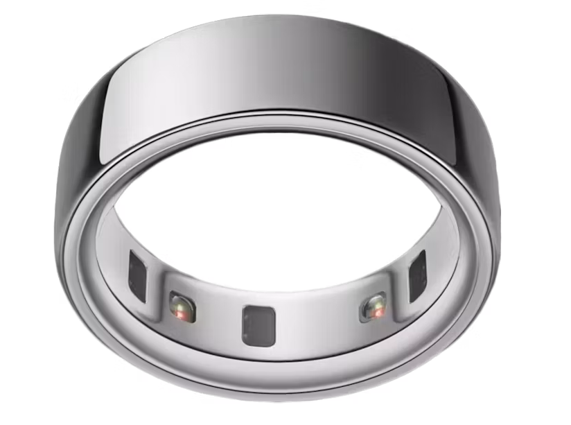
Speaking of hardware that couldn’t quite hit its design goals, TechCrunch is reporting that a class action lawsuit has been filed against Oura by customers that say the company made misleading claims about the sleep-tracking accuracy of their smart rings. Namely, that the rings could somehow detect which stage of sleep the wearer was in with only the pulse and temperature sensors it has onboard.
The complaint argues that sleep stages can only be accurately determined with an electroencephalogram (EEG), and that there’s no way for the ring hardware to actually know what’s happening in the wearer’s brain. For their part Oura has released a statement defending their methodology, and say that the ability of their rings to estimate sleep cycles compares favorably with data collected from clinical sleep studies. It should be interesting to see how this one plays out.
On the subject of products not quite doing what you expected, there’s been a story buzzing around online about a number of computer games failing to work properly on Windows machines that have installed the August system updates. Microsoft has investigated the issue and is currently pointing the finger towards RGB lights as the potential culprit.
On the surface it might sound like some kind of exotic hardware clash or interference, but the actual issue is disappointingly mundane. According to Microsoft, the August update fiddles with a system component that the software which drives some of these lights ties into, namely inpoutx64. As a quick fix they’ve provided some instructions on keys that can be modified in the Windows Registry to prevent the conflict, but it sounds like such gefingerpoken und mittengrabben may prevent the blinkenlights from performing their critical function.
Finally, we’ll end this week with an update on the ASCII CITY project that’s been making the rounds online. For those who haven’t seen it yet, this is 3D engine implemented in a single HTML file that renders a cyberpunk 3D city for players to wander around in. The latest version brings many new features to the non-game, notably the ability to enter the various buildings scattered throughout the world.
Like a lot of us [Liam Kloppers] had a problem with doomscrolling. Unwilling to go cold-turkey because he does find some utility in social media. He tried a number of things before deciding to say “Screw it” and just go full Pavlov on himself with some old-fashioned classical conditioning. Who needs willpower when you have electric shocks to dissuade you?
The key here was finding an electric-shock dog collar that could be controlled via a smartphone application, which meant he could reverse-engineer its Bluetooth protocol and get it linked up to his own software. The initial implementation ties his quick-and-dirty Python control program with a web server living on his laptop, which he’s configured MacroDroid to call on when his personal criterion for ‘doomscrolling’ is met.
With the shock collar wrapped around his leg, [Liam] was ready to test. It turns out dogs are a lot tougher than people, because even when set to a low level, the shock from the device made him toss his phone across the room and had him hesitant to even pick it up again.
Since he couldn’t bring himself to put the shock collar back onto his leg, he’s now thinking of an audible alarm, something we’ve seen work before. If you’re as unhappy with your habits as [Liam], perhaps consider a device like Commodore’s social-media-free phone before resorting to self-electrocution.
The Ting FX EP-2350 by Teenage Engineering is a standalone microphone with a few extras, including samples and built-in effect presets that can be modified by the user. It also has a distinctive design, and [Sam Holland] does an in-depth teardown that offers some insights that are worth keeping in one’s back pocket. The large, side-mounted lever in particular is an interesting bit, but more about that in a moment.
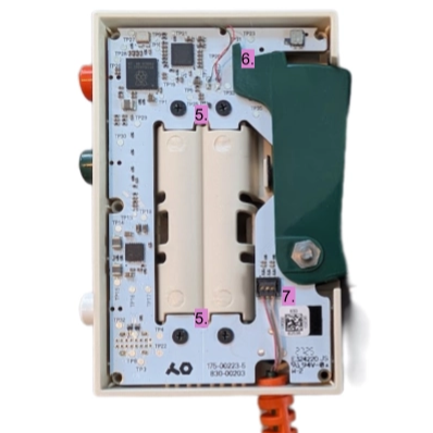
Inside the device is a single PCB, which has a cutout in the middle for a pair of AAA cells. A Raspberry Pi 2350 drives the device’s functions, supported by various components which [Sam] identifies, although he mostly looks at everything from the perspective of a mechanical engineer as he critiques the design. It’s a clean-looking, intentionally low-fi design that belies how complex the device really is.
The multi-function, chunky, spring-loaded side lever is of particular interest. It has three sensors: two switches and a potentiometer. One switch detects when the lever is at rest, or depressed by any amount at all. The potentiometer mates with the pivot point of the lever, allowing the device to directly sense how far the lever is pushed. The last switch triggers when the lever is pushed all the way in. Together, it forms an intuitive input that combines powering on (the device wakes up from sleep mode as soon as the lever is pressed) with the ability to adjust effects in proportion with how far the lever is pressed, while also bottoming out with a distinct click that itself acts as an input signal.
One other interesting bit is the light pipes that carry light from multiple indicator LEDs to the outside of the device. A textured surface acts as a diffuser and helps the lit surface look smooth, while a coating of silver paint prevents light bleed and (probably) maximizes light transmission through the plastic. Hot glue makes a pretty good light pipe material but if DIY light pipes end up in your next project, sanding the exit surface and giving the rest a coating of silver paint just might be worth a shot.
If you are a regular reader, then the odds are you have taken apart an electronic gadget, either for a fix, or simply because your curiosity got the better of you. Once inside, it’s all but impossible to help yourself from doing at least a little reverse engineering. That’s what happened when [PRBS23] took a look inside a MasterBuilt Gravity 800 Grill for a simple wire fix. But one thing led to the next, and now open source firmware for the grill is freely available!
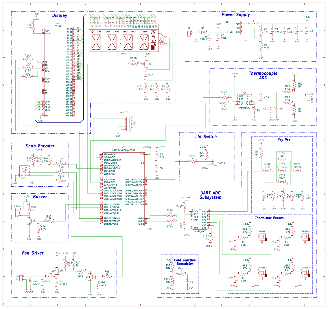
The thermistor along with the physical inputs are connected to a 16 pin chip, interfacing with the MCU over a 9600 baud UART connection. [PRBS23] cannot determine an ADC chip meeting these specifications, so the most likely answer is a cheap MCU programmed to act as a simple analog fronted.
The neatly labeled programming header is used to quite easily dump the firmware with the espflash utility. Analyzing this dump reveals a rather strange ADC correction function used by the original firmware. The necessity and overall utility of this function remains unclear, does corrects a maximum of around 40 degrees Fahrenheit.
Most of the other features ended up being at least somewhat easier. The CS1621 segmented display driver is reasonably well documented with datasheets making its implementation far easier. Likewise, the other odds and ends were implemented in a far more normal manner compared to the thermistors.
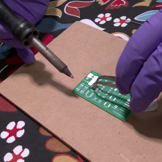
A manual skill like soldering is so much easier to learn and grasp when one can watch it in action, and there’s a brand new way to do that using virtual reality (VR). It isn’t just a series of 3D videos shot at someone’s workbench, either.
See soldering in action from any angle, with fine details preserved even close up.
PCB Hand-Soldering Basics is a series of thirteen videos that demonstrate soldering using Gaussian splats, a method of displaying 3D content that allows the viewer to freely look at things from any angle. Gaussian splats aren’t new, but what makes this different is the sheer level of detail and the fact that it’s focused on handheld tool use rather than displaying a famous location, landmark, or something similarly “big”.
Throughout the videos fine detail on the iron, parts, and the PCB itself remain visible from any angle and even from close up. Here’s a short video captured from within a VR headset that is probably the next best thing to seeing it yourself.
An educational production, it was was made in cooperation with the Department of Electrical and Electronic Engineering at Imperial College London. A few more details are in a LinkedIn post by [Tanmay Lad], who was part of the team involved in the production. The goal is to offer a unique, front-row seat to hand soldering with the ability to zoom in or look at it in 3D from any angle.
Not familiar with Gaussian splats? We’ve previously covered a great overview. They look great and are computationally cheap to render, and being able to get up close and see such detail is not really something one expects.

 Login
Login

 The standard procedure for something like this, if it can be called that, is to use Android’s built-in debugging capability to log Bluetooth communications while running the manufacturer’s application. The resulting file can be fed into Wireshark, and with patience and some educated guesses, you can usually work out the various commands and values that get passed to the hardware.