For a little while vacuum tubes and semiconductors were fighting a heated battle for dominance, with bipolar junction transistors and 1959’s RCA Nuvistor both allowing you to build a compact circuit with relatively low power usage and no high voltages. Although we now know that semiconductor technology won out overwhelmingly, that doesn’t mean that you cannot build a brand new Nuvistor board in 2026, as [Eric Schlaepfer] AKA [TubeTimeUS] recently did.
Nuvistors saw their most use in small-signal radio frequency applications, like VHF and UHF, with excellent low-noise characteristics that saw them used until the early 1970s in television sets, radios and oscilloscopes, as well as in space probes like the 1960s US Ranger Moon missions, so by that metric they had a good run.
Nothing so exciting is built in this video, sadly, but alongside a breakdown on how nuvistors work, we do see a discrete 555-style timer built using a gaggle of tetrode nuvistors, giving a pretty good idea of what using them in a project is like. Being a vacuum tube at its core, nuvistors still have the heater element, which is what gives vacuum tubes their reputation for being slow to start working and large current draw.
Despite their drawbacks, nuvistors still have a range of benefits compared to modern-day transistors, including being practically immune to electrostatic discharge (ESD) and electromagnetic interference (EMI) all the way up an EMP that will destroy most semiconductor electronics.
That said, the somewhat limited 8-nuvistor implementation of the 555 had to get a few extra pins for the heater supply, which burns up about 7.5 Watt just to allow the circuit to function. Terming it the ‘hollow-state 555 timer’, it works effectively just like any semiconductor 555, just with that extra power cost and of course no significant prospect of making it smaller, barring a semiconductor evolution as with the pixels-sized CRTs in the SED and FED type displays.
We covered the nuvistor before, including a great reference on this device, and its history that was much longer than people often assume today, as well as the vacuum tubes we use every day in for example our microwaves.
A typical response to the previous article on why PLA filament is so darn brittle. This has led some people to not use PLA filament at all, while others promote using PLA only for prototyping and throw-away parts, especially in light of PLA being compostable under the right conditions. For many mechanical parts, people turn to PETG.
Much like the PET polymer used for everything from food containers to drink bottles, PETG is durable, more resistant to degradation through mechanisms like hydrolysis and its filament form doesn’t need to be coddled like PLA does. PETG, on the other hand, tends to come from crude oil and shrugs at industrial composting conditions.
In terms of durability, degradation mechanisms and recyclability, is PETG the basic FDM filament which we should all just be using?
Polyethylene Terephthalate
PET (backbone: C10H8O4) is a polyester, just like PLA (backbone: C3H4O2). Due to how common PET is in both packaging and textile applications it’s usually just called “polyester” when used for textiles, where it is often blended with cotton and other fibers. When used in packaging PET has the sometimes rather unfortunate property of being permeable to oxygen and carbon dioxide, so that it may have to be combined with an additional oxygen-blocking layer.
This aspect of using PET for packaging is detailed for example in a 2017 review paper by Youri Michiels et al. in Applied Sciences. The main drive for using polymers like PET in packaging is due to these being more economical than traditional materials like glass and aluminium, both of which are highly impermeable to oxygen and carbon dioxide.
Consequently, a number of active and passive barriers were developed, something that is also essential in organic electronics like OLED displays when the traditional glass layers are replaced with polymers for making something like flexible displays. Active barriers can be oxygen scavengers, while passive barriers would be the application of additional materials to the basic PET film or bottle, usually in the form of a coating. This also helps to prevent the infusion of PET with colorants and aromas from food or drink, which is a common issue with recycling PET bottles.
Naturally, this can pose issues when trying to use PET materials for 3D printing, as you cannot be certain what percentage of PET waste is actually PET and what other polymers make up the remainder. This was studied by Mikołaj Garwacki et al. in a 2024 paper in Materials, with a PET-PETG blend containing PET film waste. They found it necessary to add an elastomer additive (IM) to prevent brittleness.
And this is how we get the “G” in PETG.
Triple Copolymer
Structural formula of PETG, with glycol and CHDM monomer sections. (Credit: CLauterb, Wikimedia)
The name polyethylene terephthalate (PET) already suggests that it’s more than just a polymer of purified terephthalic acid (PTA) monomers. Thus, in addition to said PTA we also see ethylene glycol (EG) monomers. This creates the basic PET copolymer as we know and love it. When we talk about PETG (polyethylene terephthalate glycol-modified), we thus do not mean the addition of glycol, but rather the replacement of said EG monomers with another monomer.
Thus PETG has a third monomer added, usually in the form of cyclohexanedimethanol (CHDM), which replaces some of the EG monomers in the resulting copolymer. In addition to PETG the ratio of CHDM monomers can create additional copolymer types:
PET -> PTA + EG.
PETG -> PTA + EG + <50% CHDM.
PCT -> PTA + CHDM.
PCTG -> PTA + EG + >50% CHDM.
Typically PETG is chosen for its high transparency and toughness properties, which is a property that’s rather useful in packaging like bottles. Although PETG FDM filament is basically PETG, something like a plastic ‘PET’ bottle can thus be PETG as well, and likely is due to the aforementioned properties.
Stability
Degradation routes of PET. (Credit: Ali Chamas et al., ACS Sustainable Chem. Eng. 2020)
One of the complaints with PLA filament is generally that it’ll become brittle no matter what, owing to the combination of increasing crystallization reducing movement within the polymer matrix, and hydrolysis shortening the polymer backbones. PETG filament has a much better reputation here, with it usually considered to be basically immune to brittleness.
The bad news here is that PETG still attracts moisture from the environment and – it being a polyester – still has a backbone that is susceptible to hydrolysis. Another common degradation mechanism is that of photo-oxidation, along with thermal degradation.
This is detailed in this 2020 review paper by Ali Chamas et al. in ACS Sustainable Chemistry & Engineering on the degradation mechanisms of various plastics within a range of environments.
As noted in the paper, hydrolytic cleavage of PET chains is very slow under neutral pH, but strongly enhanced in acidic environments. Fortunately carbonated drinks stored inside PET(G) bottles aren’t at too much of risk here, as the carbonic acid from dissolving CO2 in water is only a mild acid and thus shouldn’t hasten degradation too much.
In order for thermal degradation to occur, fairly high temperatures are required, above that for PLA, while exposure to UV light can cause photodegradation as is typically observed with many plastics. Overall long-term stability of PET polymers is not a commonly cited concern, with the cynical take of discarded PET single-use bottles potentially outliving human society being not too far from the truth.
Barring PET polymers ending up in a particularly acidic, UV-irradiated and high-temperature environment, it’s remarkably stable, even if not as much as polypropylene or polyethylene. While there are now enzymes that can dispose of PET polymers, such as PETase and MHETase, these probably are no real risk factors to your spools of PETG filament and rather just convenient ways to dispose of misprints and waste in the future.
Sample Size Of One
A pleasant sight to behold when printing with an old spool of filament.
In addition to the above theory and the perusal of the scientific literature on the topic, I figured that I would also try printing with a rather old spool of PETG filament. It dates back to the time when I was still printing on the Creality Ender 3 v2, with receipts showing a purchase date of March 2023. This spool has spent considerable time just lounging about on the FDM printer’s spool holder before being stuffed back into a sealed plastic bag and forgotten about until recently.
Digging this Reprapper-branded spool of clear PETG filament out of storage, I was momentarily dismayed at it having been stored by past me in just a resealable bag with no attempt at a vacuum, just with a probably expired baggy of forbidden silica candy tossed inside the bag. Let’s consider this a worst-case scenario.
Feeling particularly adventurous, I decided to not even dry this much-abused spool of PETG filament and just see what happens when printing on my Neptune 4 bed slinger. After some initial fiddling with loading issues I fixed this by snipping off of the dodgy tip of the filament, presumably due to its mangling by the Ender 3 v2’s extruder gear and hotend.
I still had my worries about the extruder teeth marks from the previous printer and the presence of a few bends in the filament that made me suffer PLA-related flashbacks, but after slicing up a cable chain model that I had printed many times in PLA before, the printing was very much uneventful.
As can be seen in the photo, I was greeted by a happy print result. While keeping an eye on it for the first layers I did notice a bit of oozing, but after a few minutes it normalized and the cable chain elements were printed cleanly, including the big overhangs. I was able to clip the elements together as well without any brittleness or other issues.
I probably should have turned on the auxiliary cooling fan on the Neptune 4 as PETG prefers things cool unlike PLA, but even with this YOLO printing attempt with a neglected spool of PETG I was left impressed. After my recent experiences with PLA I was bracing for at least a few hours of troubleshooting, but this was almost boring.
Vibe Check
With this printing experience and the scientific literature put side by side, I think that they concur. Despite me taking no precautions at all, even a more than three-year old neglected spool of PETG filament printed just fine. There were no signs of stringing or other issues that would prevent me from just queueing up another print. Although I’d still advocate at least for keeping PETG spools in at least a sealed bag or container, it’s not nearly as fragile as PLA.
Since my previous article on PLA’s brittleness, I have opened its still factory-sealed twin in the form of black PLA and found that although it’s not nearly as brittle as its white sibling, it too began to snap off if left at anything beyond a gentle curve. Clearly this puts a pretty big expiration data on PLA filament, but it’s still an open question whether it was just this particular batch of Sunlu PLA filament.
In light of all this, I think it is fair to say that PETG is by far the most ‘no fuss’ filament for general use, with PLA only having its theoretical composting advantage. Yet when taking into account that this is only guaranteed for pure PLA without additives, and PET-degrading enzymes exist, that theoretical advantage doesn’t seem so convincing anymore.
The phones! They were one of the basic utilities of the 20th century, and were just about as reliable as death and taxes. Even when then power grid went down, you still had a fair shot of getting a phone call through thanks to the reliability of the Plain Old Telephone Service.
Generally, we expect our telecommunications networks to be supremely reliable. There is no moment of the day when someone doesn’t need to make a call, particularly in emergencies, and the wheels of industry and commerce depend on constant connectivity these days. Tolerance for failure is generally very thin. Despite this, and the efforts of engineers to maintain uptime at as many nines as possible, Telstra fell badly short on July 8th, 2026. The company had a nationwide outage that affected 8.8 million people, leaving them unable to make calls or connect to the network at all.
The cause of the outage would prove to be particularly embarrassing. Telstra owns and operates a highly advanced cellular network, offering 4G and 5G service across the nation’s cities and much of its outback areas. The company may outwardly appear to be a shining beacon of modern connectivity, but there was something dank lurking in the company’s server closets. Namely, three aging network time servers that had the capacity to bring the whole system to its knees.
The NTP server in question is old enough to still rock a vacuum fluorescent display, something you don’t see on a lot of modern network hardware. Credit: Microsemi
The culprit? A Microchip Technologies SSU 2000 NTP server. The model dates back to the early 2000s. Twenty four years later, Telstra still relied upon three of the units to provide network time protocol (NTP) services across its network. The servers were generally perfectly adequate in this role on any given day. That was, until the Melbourne server had a wobble.
A technician was working in the early morning to replace a backup power feed in the chassis housing the server. This caused the server to be rebooted at 3:38 AM, which normally would not be a problem. However, at some point in the last two decades or so, the server had gone through a configuration change. While it was originally intended to be a Stratum 3 NTP server, getting its time reference from a Stratum 2 unit, that process had failed at some point. It had been reconfigured instead to use its internal GPS card to gain time directly from the satellite network instead. Unfortunately, the server was also remarkably old, and suffered from a well-documented GPS date rollover bug, such that when it rebooted, it reported the time as 2006 rather than 2026.
Victoria’s V/Line train services were unable to run, as the Telstra network outage made communication across the system impossible. Credit: Thomas Hobley, CC BY-SA 4.0
The problem that stemmed from this was because time is critical to authentication. An endless cascade of devices downstream of the NTP server picked up the wrong time, and started using it to sign digital certificates and the like. This immediately caused other systems on the network to reject the spurious traffic with certificates that were 20 years out of date. The impact was swift and vast—Telstra was quickly facing a nationwide outage affecting millions of customers.
The issue was first detected at 4:20 AM. The naughty server was isolated by 7:11 AM, but it would take until 10:30 AM to identify all the network components which had received erroneous time data. It took several hours further—until 4 PM—to properly quell the NTP issues. In the meantime, a significant portion of the country had seen its phones offline all day, and entire rail networks had ground to a halt as their Telstra-based communications systems went completely offline.
Later submissions to a government inquiry would reveal Telstra had received two reminders to patch the GPS card, in 2020 and 2022. The vendor itself had issued warnings about the GPS rollover bug as early as November 2000. A decision not to fix the bug had been taken as recently as January 2026, because the undocumented change to have the server rely on GPS time was unknown, and thus the update was considered unnecessary. Simply patching the system would have prevented the issue from ever occurring in the first place.
When the outage became apparent, Telstra notified the Triple Zero Custodian, a body founded in 2025 to oversee the integrity of the emergency service. Credit: Telstra submission to government inquiry
The issue once again brought telecommunications availability in Australia to the forefront of the conversation. Repeat outages across Australian mobile networks have led to particular concerns about the ability for people to reach emergency services by calling Triple Zero from mobile handsets. The latest failure on Telstra’s behalf has led the local telecommunications industry to issue new guidance to the public on what to do when a call to Triple Zero doesn’t go through.
Modern handsets are designed to switch to a different cellular network in the case an emergency call can’t be connected—a process called emergency camp-on. However, this process takes time, and the caller will often hear silence on the line while the phone is attempting to connect. The new advice is that callers should hang up and try again straight away if their first call to Triple Zero doesn’t connect within a few seconds. On the second call, though, the phone should be given up to a minute to find another network to get the call through.
In the case of this outage, camp-on functionality worked—some 3,200 Triple Zero calls were passed to Optus and TPG networks when Telstra’s failed. However, there were some ongoing issues that saw a further 604 Triple Zero calls fail over the period to 2 PM the next day.
Overall, Telstra’s failure was a major one. It’s rare for a major network to go down so completely and over such a wide geographical area. The fact that it happened because of an undocumented change to an ancient network appliance is all the more embarrassing. It will drive home the message that documenting even seemingly minor changes is important, with the lesson likely to be told in the halls of the Australian telco for some decades to come.
One of the stories of the last few weeks has been that AI companies have been scanning books in very large numbers in order to train their models with content guaranteed to have been written before 2002, and thus AI free. It’s caused some outrage, because of the size of the operation, and because the scanning process is destructive. In particular the phrase being bandied around is that these are rare books, and it’s this phraseology I find problematic. I think it’s time to unpack why that is the case.
It’s Not Book Burning, Folks
Before I worked for Hackaday I had a long career in and around the publishing industry, mostly on the electronic side, but from time to time crossing paths with my colleagues in the world of paper-based publishing. I understand the appeal of a good book, I’ve spend a lot of my life among bibliophiles, and let’s just say I own a few books myself. In particular I understand the symbolism of destroying books, bringing to mind as it does the actions of repressive regimes. I have stood in Bebelplatz in Berlin where the photo of Nazi student organisation members burning the library of Magnus Hirschfeld’s institute was taken in 1933, and if you know me, you’ll have an idea why that’s close to home. But for all that, what the AI companies are doing is not the same thing.
In this case they’re destroying the books for two reasons. Firstly, as I remember from a previous employer in the publishing world, it’s much easier to digitise a stack of papers than it is a bound book. Thus I’m pretty sure that’s one reason they remove the binding before digitising the pages. Then secondly, as I understand it it’s a copyright issue. If they buy a book, digitise it, and destroy the physical copy, they can legitimately claim that only one copy of it exists, and they hope, sidestep copyright claims from publishers.
When Rare Maybe Isn’t Really Rare At All
You’ll only see one of these numbers on a book published since 1970.
Perhaps the most pertinent question then is just what are the books being scanned and destroyed? They’re almost universally described as “rare”, but is that accurate or sensationalist? It brings to mind a dusty library filled with priceless tomes hand-transcribed by monks which it would be a crime to destroy, but there’s something that explodes that vision in an instant.
If you read the reports of what’s happening, they are ordering books by ISBN number. That’s an international system for identifying books, which was only introduced in 1970. If they’re ordering a book by its ISBN, it’s no medieval illuminated manuscript.
So the books being scanned and destroyed are relatively new, but can they still be described as rare? In that case just like anything else mass-produced since 1970, how many survive depends on the size of the original print run and how valued they have been since. So a few of these books can be physically rare in the sense of being uncommon, but if they are next-to-valueless, it’s fairly obvious nobody has particularly cared about their survival up to now. It’s likely that any books printed since 1970 which are both rare and of value will have their future assured, so the AI industry is not committing the wanton destruction of culture the reports would like to suggest.
You Need To Know Just How Many Books Get Pulped Every Year
People are often shocked when they find a dumpster full of books for recycling. Ricky Shore, CC BY-NC-ND 2.0.
I’m left feeling that a combination of the symbolism of destroying books along with a distaste for AI companies has inflated the status of these books well beyond their worth. If people truly had a care for old books they would be shocked to know how many are pulped each year by the paper recycling industry.
The publishing industry has been churning out mass-produced books for centuries now, so the world is awash with old books. Where do these newly-minted bibliophiles imagine they all go, to the Great Library In The Sky? I haven’t even touched yet upon the publishing industry, which pulps vast quantities of brand new unsold books every year. Where is the outrage, I ask?
We all love to dunk on AI companies, and Heaven knows, there are plenty of reasons to do so. Among all those reasons, sadly destructively digitising books is pretty low on the list. Please, ask the other questions, the ones they really don’t want to answer!
When I got back into SLA resin printing recently, I knew that I’d inevitably have to deal with the agony of failed prints and of course resin spills. This moment eventually came, and I felt motivated to treat mistakes as teaching moments on aspects like how to properly prepare an SLA build plate in terms of angles and supports or how to deal with failed print aftermaths.
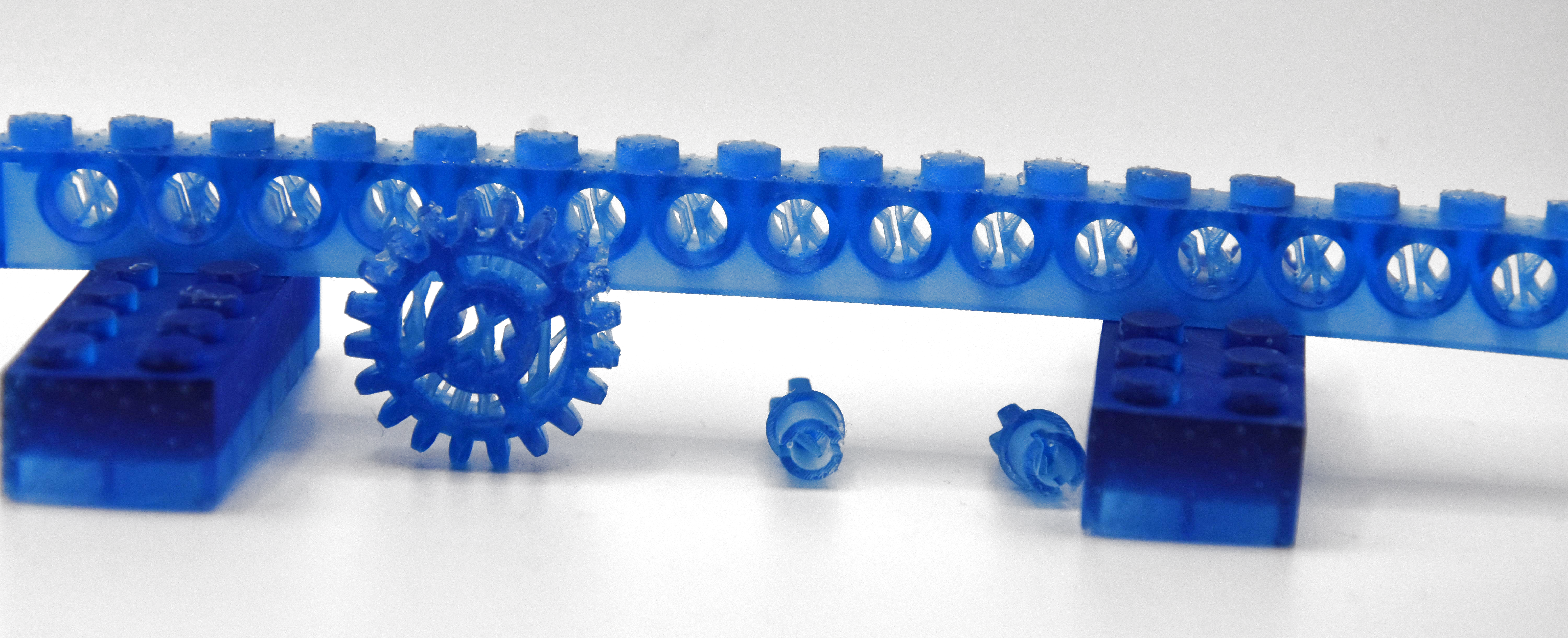
Before moving on to the disaster, I’d like to first start with a look at the resin print of the previous article, which contained a number of fairly small parts. These I had oriented and supported almost fully using the automatic methods provided by the ChituBox slicer software, and worked about 90% as I had hoped, while leaving plenty of room for improvement as well.
Overall, preparing an SLA build plate in the slicer isn’t quite the same as for an FDM printer, mostly due to one phrase that strikes fear in the heart of anyone who has ever done resin printing: “peeling forces”.
Not Bad, Not Great
For last article’s resin print, I had to put a number of models onto the build plate in the slicer, after which I mashed ‘auto arrange’, ‘auto orient’ and then ‘auto support’ in their respective tabs. I did change the orientation of the beam so that it wasn’t pointing straight upward any more, as I wasn’t going to wait a few extra hours for it to print just for that single object.
This then got me the following overview including a veritable forest of supporting structures:
You’re going to enjoy peeling off those supports later.
By playing it safe, I managed to get everything printed without any glitches other than my previously mentioned fight with the resin auto-feed system of the printer. Of course, by leaning heavily on defaults, I also got backstabbed by the slicer’s overzealous use of supports, especially where it was highly undesirable, such as inside parts of the LEGO Technic-compatible parts:
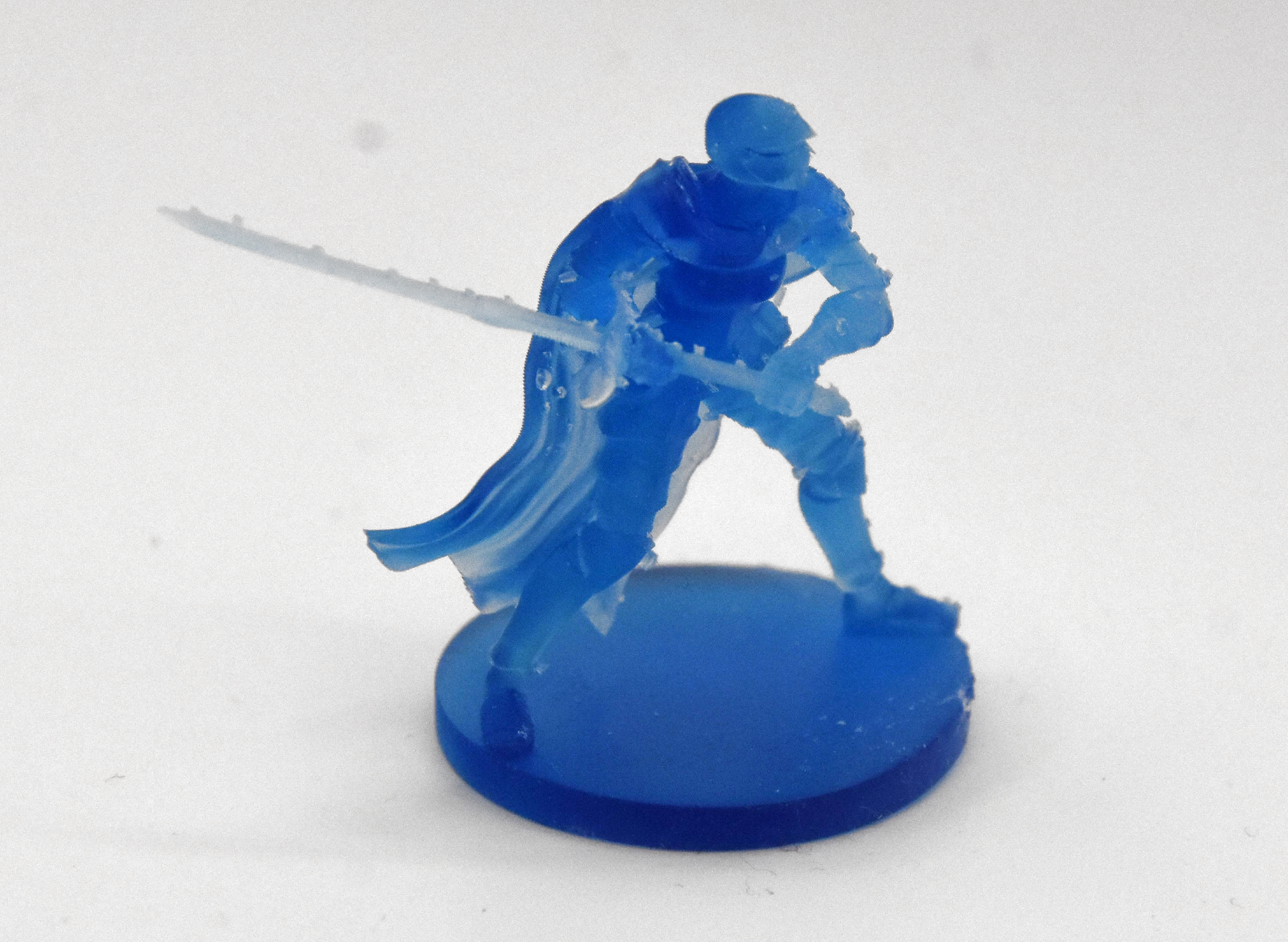
By rotating the figurines to be printed upside-down relative to the build plate this also meant having lots of ugly marks left by the supports, both on the happy buddha and the female knight figurine.
Here the fix seems rather straightforward: angle figurines so that supports contact things like the bottom of a surface where it won’t be as noticeable. Also inspect the auto-generated supports to remove any that are in naughty places and perhaps do some manual supporting if you feel particularly confident.
I did look at a few “how to do supports right” videos and written tutorials, and the general advice seems to be to simply forget about auto-generated supports.
For me an amazing aspect was that both figurines were angled upside-down by the slicer, when everyone prints them with the base towards to the build plate. Exactly how ChituBox’s algorithm here works is a complete mystery to me, but I reckon that this slightly confusing experience may have contributed to the subsequent disaster that occurred with another print.
Simply Bad
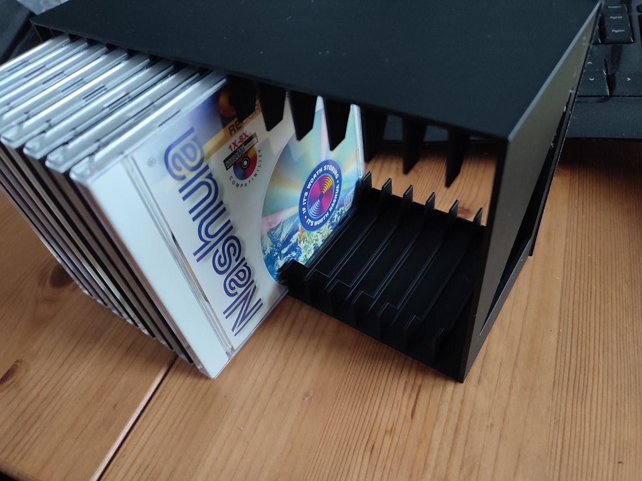
The FDM version of the CD rack in black PLA passing QA.
Where things slid sideways and wrapped themselves at high velocity around a phone pole was when trying to print a 16-slot CD rack, specifically this rather nice model by [zenitar3d] from Thingiverse. On an FDM printer this is braindead simple to print: you slap it on the build plate in the slicer, do a sanity check that it physically fits, slice it and let ‘er rip. My only issue here was that OrcaSlicer deemed it necessary to add a brim, so that took some sanding to clean up a razor sharp edge.
On the resin side of things, you enter a torment nexus: you can slap the part on the build plate, but then you risk elephant foot — a thickening at the base where exposure time is longer than for subsequent layers. Even if that’s of no concern, you still need to violently remove the part from the solid metal build plate, which is highly likely to cause damage.
If I still had the LD-002R printer with its flex plate, an aftermarket modification that I had fitted. This would be of no concern with a mere flex-and-pop, but here I’d have to violently wield a metal scraper to convince the build plate and cured layers to part ways. Clearly I need to look into flexible build plates for current SLA printers.
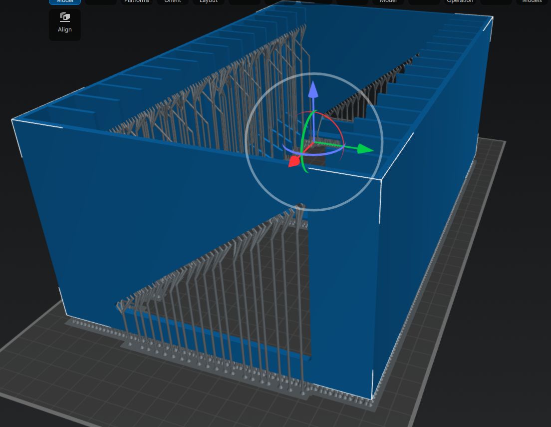
I did try to use the same auto-angle and auto-rotate approach in the slicer, but ChituBox would just always put part of the model outside of the printing area. After a while I grew tired of this and just printed it with the part slightly lifted off the build plate with medium supports like this:
Anyone who has ever done any resin printing cringes at this screenshot.
In my defense, I did this in the midst of yet another European heatwave with zero air conditioning, so maybe that had sufficiently fried my remaining brain cells. Regardless, the results were rather predictable.
Carnage
A little while later I had the good news in the sense that the supports were printing beautifully, but also bad news in that the actual model had been ripped off the supports by the aforementioned peeling forces.
Cue sad trombone SFX.
In hindsight this was obvious: the quite solid surface of the model has significantly more surface area than the area contacted by the supports. At the first attempt to peel the newly cured model layer off the nFEP (PFA) film, the tug of war resulted in the supports winning out and the print being a total failure.
You could call this the ‘FDM spaghetti’ equivalent with resin printing, where the FDM’s extruder is printing in empty air, but unlike with FDM printing the subsequent clean-up is less of a sighing, brushing away bits of thermoplastic and trying again with the glue stick, and more of a chemical hazard situation.
Dealing with an SLA resin printing failure sees you draining and filtering the resin from the vat, carefully removing any solid resin from the vat’s film and curing the failed parts so that they can be safely disposed of. All while suited up with gloves, eye protection, and at least a half-face mask with A1P2 filters that still leave you plenty of opportunity to consider whether SLA resin or IPA smells worse when the copious amounts involved of both try to overwhelm the filters.
Clean-Up Detail
All of this is perfectly fine.
Where the whole kerfuffle got even worse was when the whole auto-feeding of the resin caught up with me. After ripping the bottle out of the machine I had noticed that the GK3 Ultra had for some reason pulled a vacuum inside the bottle, which could explain some of the issues that I had experienced. This did however also mean that its internal volume had decreased due to the bottle’s deformation.
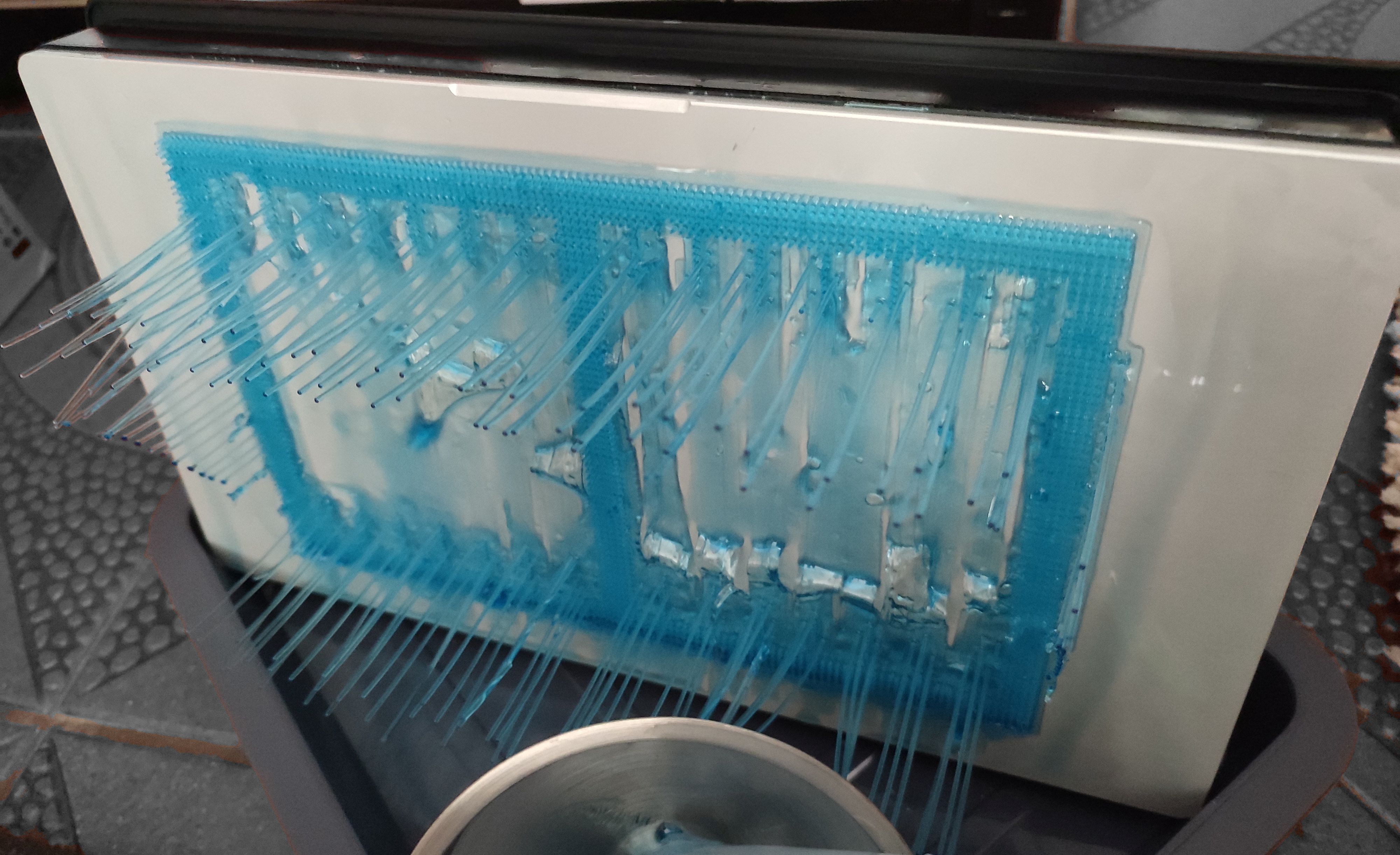
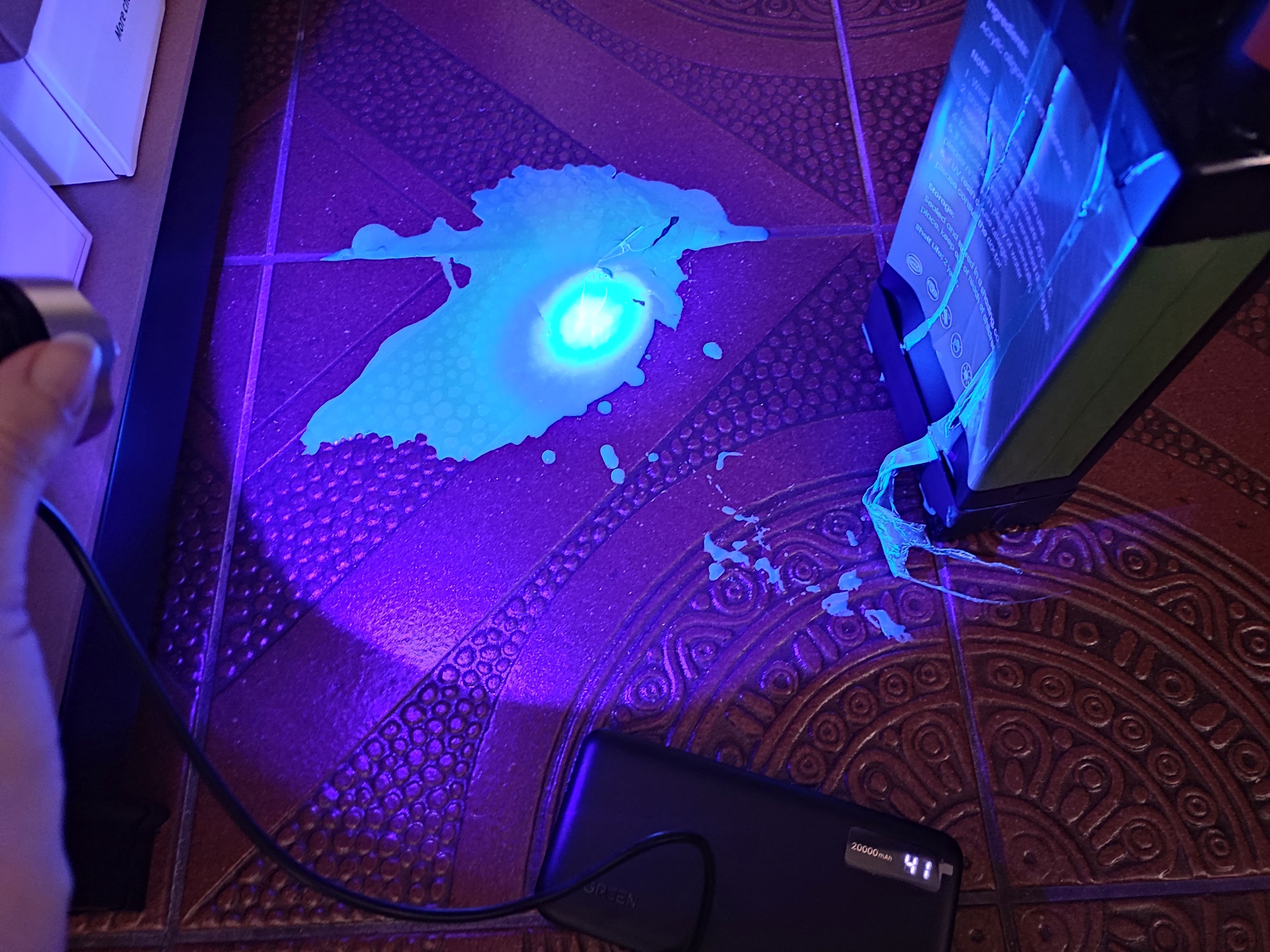
This was a detail that didn’t quite register with me until resin that I was pouring through the filter into the bottle was overflowing onto the floor. Cue copious amounts of colorful cursing and a dash for the paper kitchen towels, followed by a rather illuminating UV exposure session using a handheld UV lamp. Fortunately cured resin doesn’t bond well to tile flooring, so it can be peeled off after curing and tossed into the regular household waste. The pro-tip here is to always use silicone underneath potential resin spills. If only I had done so.
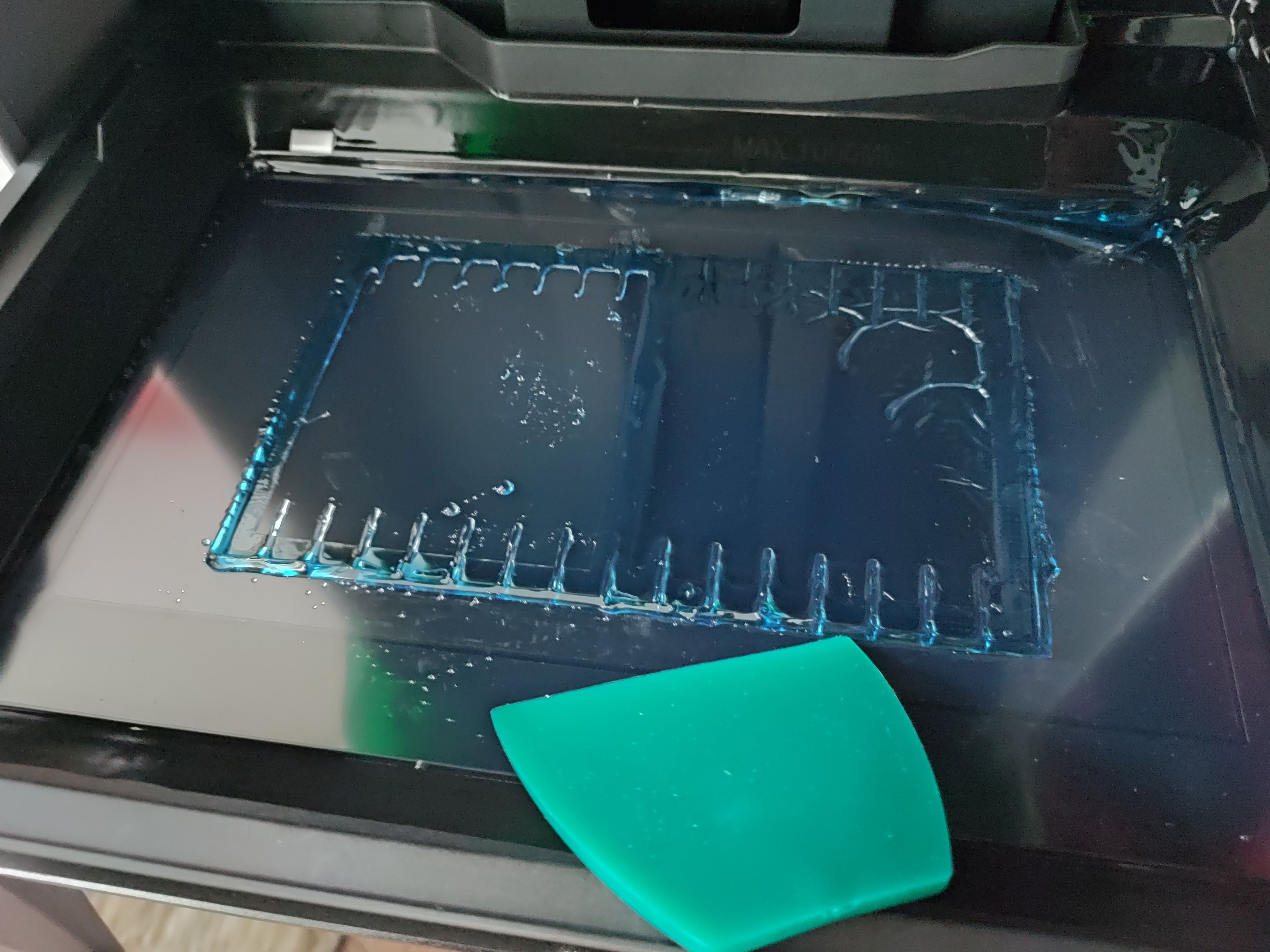
With the floor clean once more, the next challenge was to get the vat cleaned up again. The provided silicone scraper was useful here, but you absolutely need that spray bottle with IPA to soften up the connection between the PFA film and the cured resin.
This calls for IPA and elbow grease.
Using the built-in vat curing feature I could cure most of the remaining resin in the vat, but still had to use the handheld lamp to get to corners where it didn’t reach. This is the part that I’m still working on, making sure everything is clean and the PFA film undamaged before I throw myself again at another printing session.
Lessons Learned
As they say, spilled milk, or resin.
I think the primary lesson that I have learned here is that I still do not comprehend why consumer resin printers insist on having that solid lump of metal that they dare to call a ‘build plate’ — an immovable surface that you have to violently assault with a scraper after printing to make it release printed parts.
After mostly printing with the magnetically attached flex plate on the LD-002R – of course after adjusting its Z-height correspondingly – it still feels like time hasn’t moved at all here.
As a friend of mine remarked when I reported the print failure described in this article, it’s also rather astounding that there’s no simulation of peel forces in slicers to get some idea of whether your supports game is overkill or weak sauce. There are some resin printers that even try to reduce the peel forces by tilting the vat – such as the Prusa SL1S and Form 3 – and there are various ‘tricks’ to reduce the peeling forces, such as lubricating with silicone and PTFE oil, many of which I too have tried with the LD-002R with unclear results, but ultimately you just want to ‘science’ it, as the kids say.
Overall, a resin printing failure isn’t the end of the world, as long as you are mindful of a potential mismatch between the air volume in the target bottle and the resin volume in the vat you’re pouring from. Resin is only nasty until you blast it with UV, when it turns into relatively harmless plastic.
All of that said, I’m still torn on that CD rack model. Theoretically the GK3 Ultra has the build volume for it, surpassing the Neptune 4 in two directions, but it’s not easy to prepare a plate in such a way that the model isn’t ripped off its supports, is not disgraced by a massive elephant’s foot, or worst case the build plate wins and the FEP/PFA film loses the tug of war and rips.
Did I mention rips in the vat’s film? That’s another thing I experienced with the LD-002R back in the day. I was lucky that the resin spill was fairly contained, but I was puzzled for a while why the prints kept failing until I actually drained the vat.
Anyway, after all this learning, it’s time to reorganize and see what I can improve when I next hurl myself at this whole SLA resin printing topic.
Powered machinery started the industrial revolution, and it was automation that kicked it up another notch in the 20th century. The ability for machines to make things by themselves spurred increased output and in turn boosted economic growth. The concept became widely popular for manufacturers to implement, as any change with serious economic benefit tends to do. Fast forward to today, and advanced robots and fancy machine vision systems running on powerful computers are the norm in modern factories which create the many wonderful products that we all purchase, use, and enjoy.
Once upon a time, though, things weren’t so sophisticated. [Nicola Cimmino] came to Hackaday Europe 2026 to tell us all about a remarkably simple 1-bit CPU that used to run factories.
Logic, But Make It Cheap!
Nicola Cimmino used to frequent a facility that used to recycle electronic waste, which sold old bits and pieces of hardware by the kilo. Many times, Nicola would pick up odd boards with an eye to repurposing components for future projects. Eventually, one unremarkable looking chip caught his attention—the Motorola MC14500B. This chip was rather unique, being a rather simple processor with just 16 instructions and a 1-bit data bus.
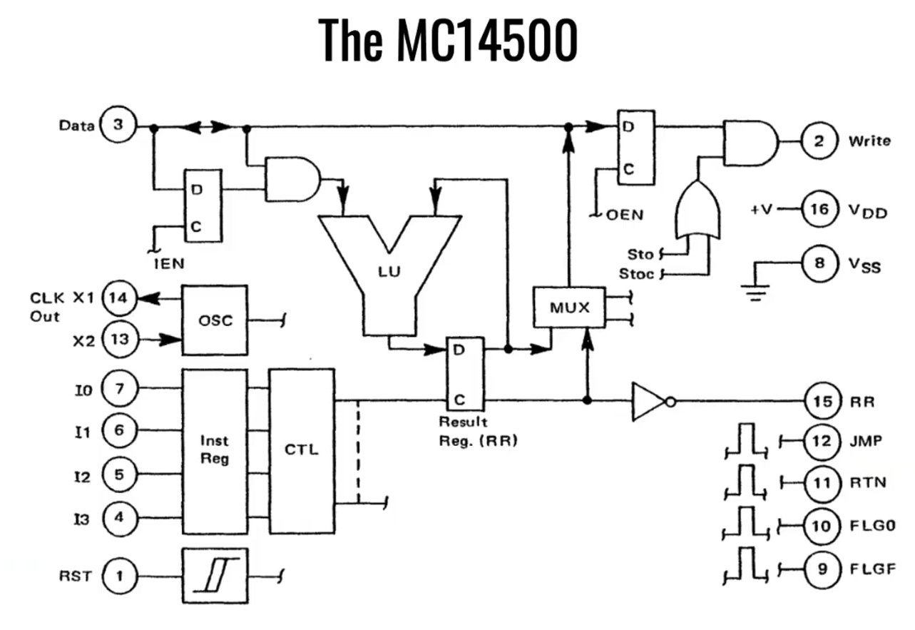
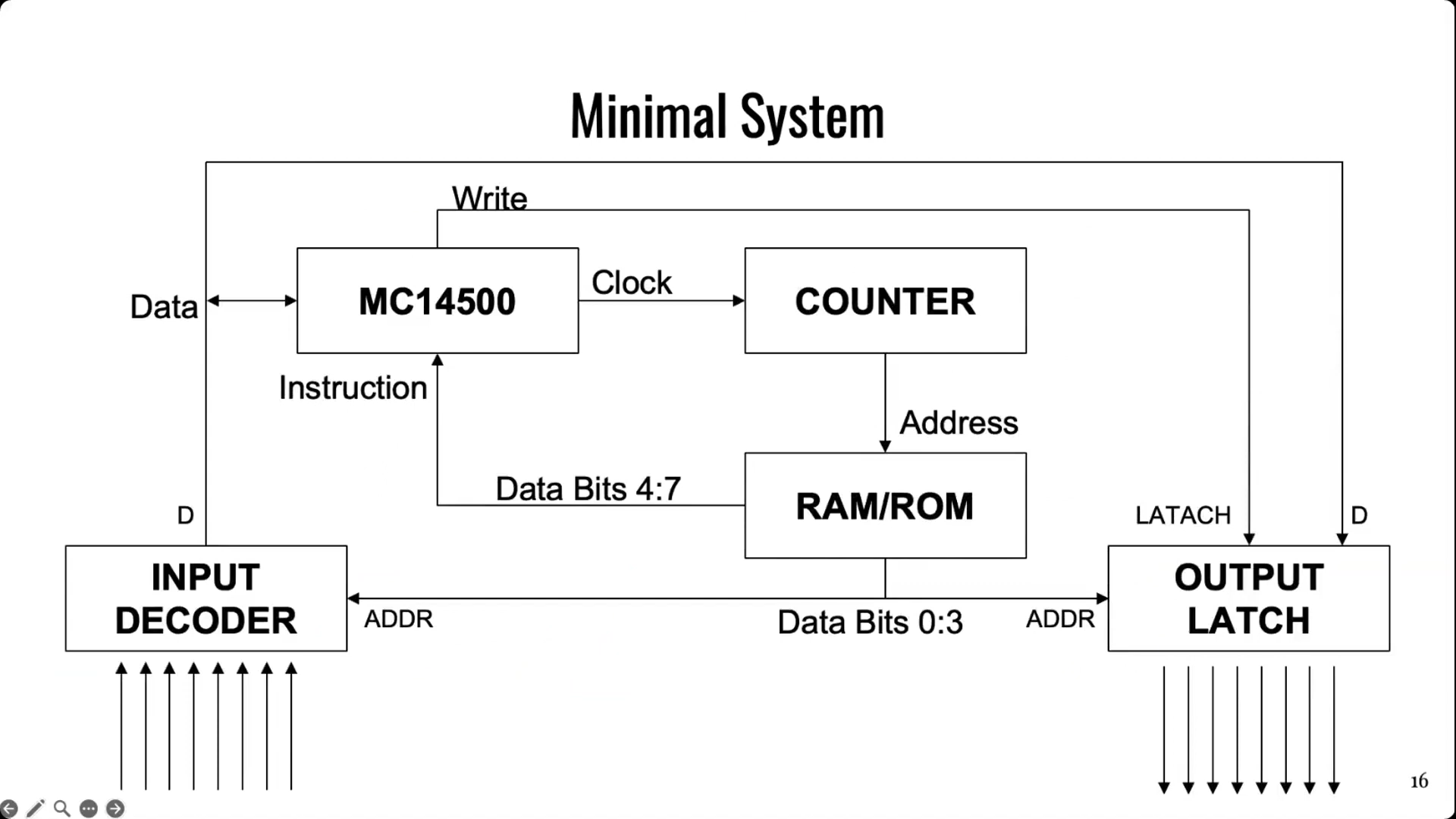
The simple architecture of Motorola’s basic 1-bit chip. Credit: talk slides
It’s worth examining the era in which this chip existed. Intel dropped the 4-bit 4004 in 1971, with the famous 8-bit 8080 landing in 1974. The Zilog Z80 came along in 1976, similarly an 8-bit design. And yet, when Motorola released the MC14500 in 1977, it landed with a rather slimline 1-bit design instead. Nicola notes that this likely came down to price, since populating a chip with more transistors cost more money quite significantly back in the 1970s. If the job could be done with less, it would make the part cheaper and thus more popular in the market. Bearing this out, Nicola explains that a 1976 Zilog Z80 used 8,500 transistors and cost around $200 USD, while an MC14500 used just 500 transistors and could be had in 1977 for the bargain price of just $5 USD.
It doesn’t take much supporting hardware to get an MC14500 up and running. Notably, though, there is no memory or program counter on board, so those have to be added externally. Credit: talk slides
Back in the mid-1970s, automation in industry often consisted of simple logic that was handled by cabinets full of relays. This took plenty of bulk, required hard-wiring everything, and also involved plenty of electromechanical parts that could wear out. Changing logic required manually rewiring things which could be fussy and tedious at the best of times. In those days, the Programmable Logic Controller was just coming into use, developed to be a reprogrammable system for industrial automation tasks that was more flexible and reconfigurable just by reprogramming it.
The MC14500 sprung up as a useful tool at this time, powering a great many programable industrial systems. It was designed to offer the bare minimum requirements for its application, while leaving extraneous hardware for designers to implement if and when it was needed. The architecture is simple enough for Nicola to explain with a single slide. The chip came with a 1-bit logic unit, operating with a result register, a 1-bit accumulator and the data bus. A minimal system could be lashed up with the MC14500, a counter, some external RAM or ROM (since none was onboard), and an input decoder and output latch of 8 bits each. This setup would only allow for doing combinational logic, since there is nowhere to store the current state of the system. However, hooking some outputs back to the inputs could allow for sequential logic, since it would allow for storing the current state of the system via those outputs. Nicola then steps through various other configurational changes to addressing and system architecture that could be made to optimize the MC14500 for use in different ways.
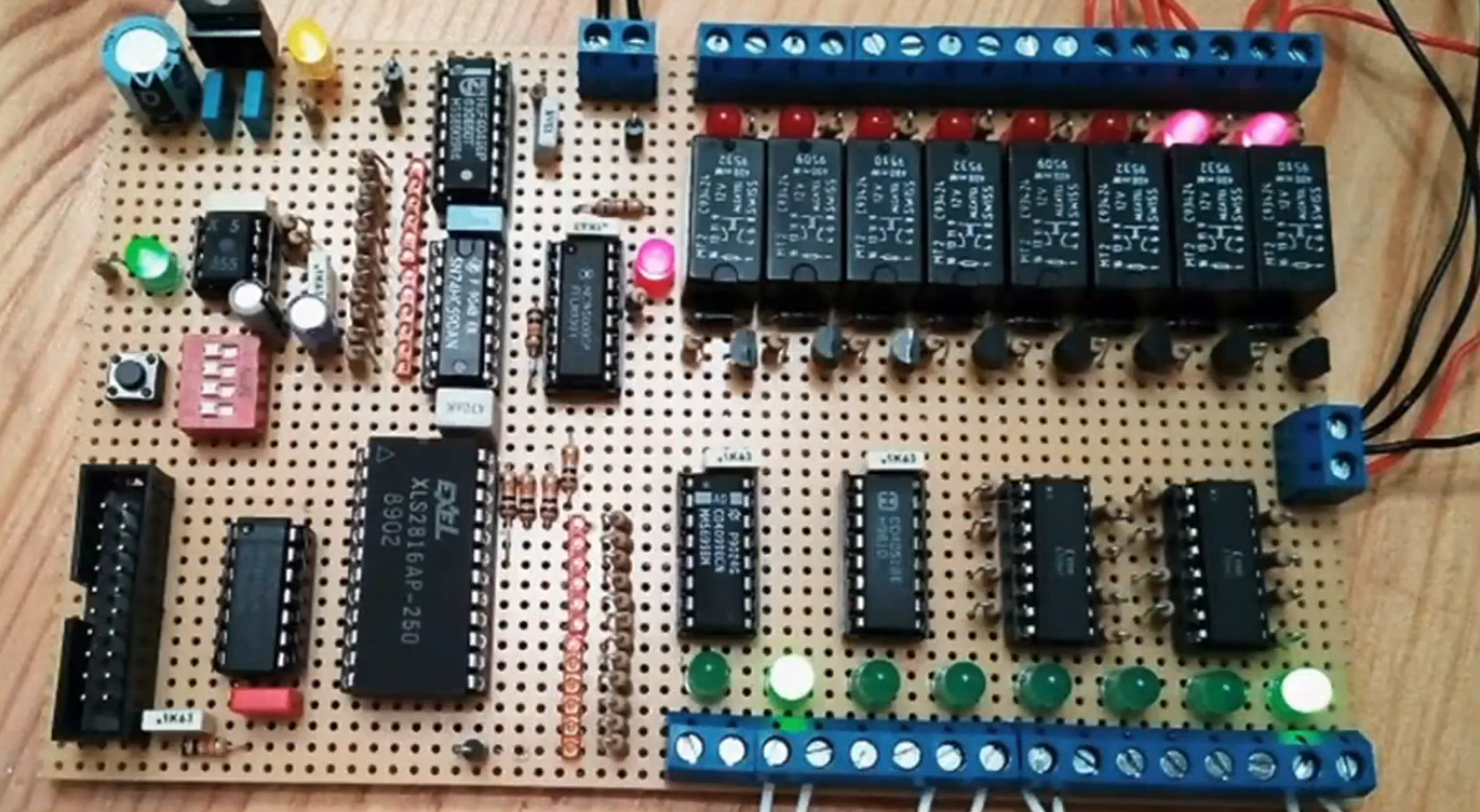
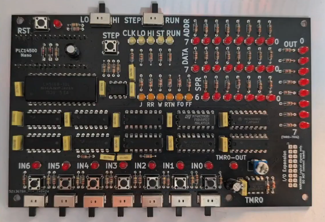
Nicola built a homebrew MC14500 system, allowing him to get to grips with the classic chip. Credit: talk slidesA more polished version came later, built on a custom PCB. Credit: talk slides
If you wanted to get to grips with using an MC14500 in industrial contexts, you would do well to pay attention to this talk, even if it came out some 40 years past the part’s heyday. Beyond the basic system architecture, Nicola explains how to use the limited instruction set, and how to get such a system executing simple programs in ladder logic, which remains somewhat of an industrial standard to this day. Beyond that, he steps up to more complex logic, like if/else conditionals and the use of some of the weirder instructions of the chip. He then shows off the hardware he built himself—both a breadboarded MC14500 setup built with wirewrap, and a more polished version on a custom PCB.
It’s not every day you get to learn about the nitty-gritty details of working with industrial hardware from the ground up. And yet, that’s exactly what Nicola brought to Hackaday Europe 2026. It’s an excellent primer on the topic, and also simply just good fun if you’re a fan of electronics and logic itself!

 Login
Login