Normal view

There are new articles available, click to refresh the page.
Yesterday — 12 September 2026Hackaday

Big Infinity Mirror Clock Invites You To Gaze Deeply

12 September 2026 at 16:00

[Andy Huot] has a fantastic-looking infinity mirror digital clock that really raises the bar. It uses high quality components, smart use of RGB LED animations, and a clever “stacked diffuser” vertical design to the 7-segment display elements that really enhances the infinity mirror effect. It needs to be seen in action, so check it out.

The end result is expressly portal-like, with the smooth animations of the LEDs really playing into the effect. The size helps, too. It’s 24 inches in diameter, giving it considerable presence.
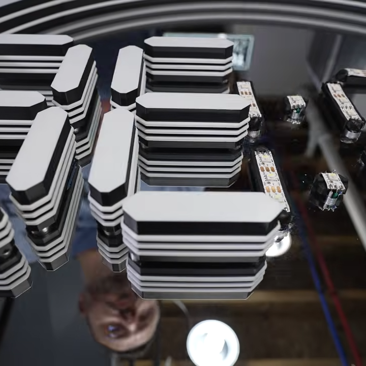
The stacked diffuser design for each display element really enhances the effect.

A basic infinity mirror design consists of lit elements sandwiched between a reflective back surface and a partially-reflective, partially-transmissive top cover. That same basic principle is used here, but with great care given to ensure nothing so much as a fingerprint spoils the illusion. For example, the top cover is a disk of acrylic with a 90% reflective film affixed to the inside surface. That’s easy enough to DIY with some car tint, but [Andy] found that for the very best results it was worth having high-quality film professionally applied.

We like the use of 3D-printed custom jigs for soldering the segments of RGB LED strips, and holding the pre-measured wires in place with some putty is a great way to keep them in place while working. In case you’re wondering, the mirrored acrylic making up the back wall has holes in it for mounting each segment’s LED strip in a holder, and running the wires to the rear.

The video (embedded below) documents every step of the assembly, and it’s a serious build. While the design files for the 3D-printed parts are not free, there’s certainly enough detail for an enterprising hacker to replicate the design in their own way.
The Heavy Disco-Ball Satellite Designed to Do… Nothing

12 September 2026 at 07:00

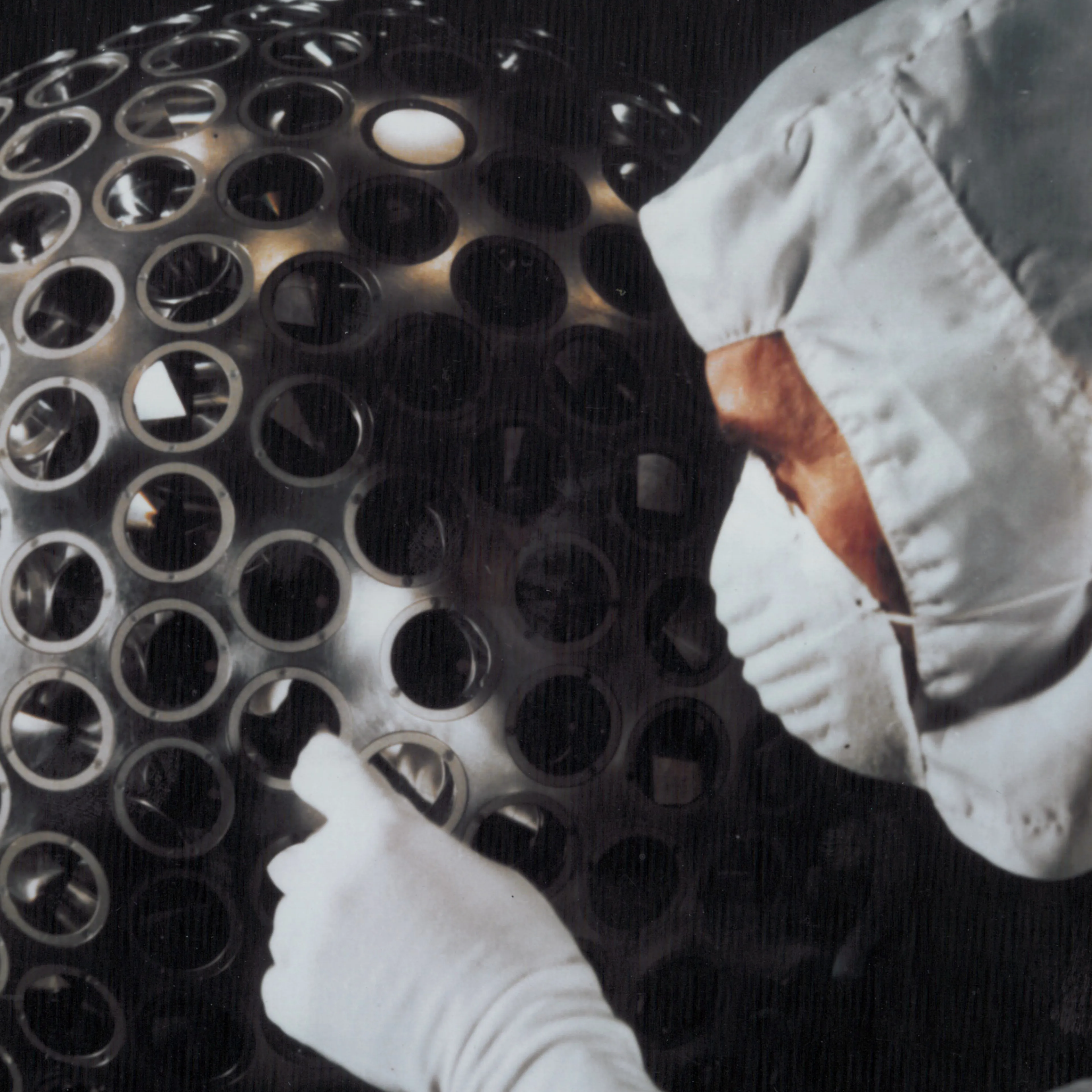
Launched in 1976, LAGEOS-1 (LAser GEOdynamic Satellite) is unusual in that it contains no instrumentation, no electronics, no power supply, and no means of propulsion. It’s spherical, weighs just under 407 kg, and looks a bit like a disco ball. It may not be accurate to say it does nothing, but unlike most satellites its role is entirely passive. It’s also one of the oldest scientific satellites still in service.

The lens-like objects covering the surface of LAGEOS-1 are corner cube retroreflectors, which have the nifty effect of always reflecting incident light right back towards its source.

Ground stations fire short laser pulses at it and measure the time it takes for the light to return, a form of time-of-flight ranging. Since LAGEOS-1’s orbit is highly stable, it provides a reliable reference point for measuring even tiny changes in the Earth itself. The size, shape, rotation, and more of our planet can be measured as a result. LAGEOS data (LAGEOS-2 was launched in 1992) has also been used in tests of general relativity.

Its orbit and construction were deliberately chosen so that atmospheric drag and other disturbances would be minimal. The simple, maintenance-free design combined with an extraordinarily stable orbit means LAGEOS is expected to circle our world for millions of years to come.

LAGEOS-1 also contains a message to the future in the form of two identical plaques prepared by Dr. Carl Sagan just in case there’s anyone around to find it some day. Check out the short 1975 video from NASA, embedded just below.

Before yesterdayHackaday

How To Fold Curved Lines in Metal Without Fancy Tools

11 September 2026 at 22:00

Folding a sheet of metal in a straight line is one thing, but how does one fold multiple curved lines into a sheet of aluminum without fancy machines? [John] demonstrates how to do exactly that with little more than hand tools and a fair bit of patience. The secret is drilling a lot of small holes along each fold line.

Complex shapes are possible with planning, hand tools, and patience.

First, a bit of background. [John] wanted to fabricate a curved piece of aluminum as cover that would match the sleek aerodynamic lines of a Belly Tank Lakester. The trick is that there isn’t a single straight line to be found, and the fold lines are all curves. How can one do such folding with only hand tools?

[John] found that fabrication was possible by drilling small holes all along each fold line, then carefully bending as needed. The line of holes weakens the metal, acting like a score line, and allow the required curves to be made cleanly. There’s some finishing work and straightening involved, but the hard part of making the actual folds is taken care of.

One method that didn’t work was cutting a shallow groove in the metal to create something like a pre-scored fold line. [John] tried this and found that while the metal does indeed fold along the weakened line, the aluminum tends to crack in the process. When making a line of holes instead, the metal between each hole bends nicely.

This technique does mean the finished part ends up with small perforations along each fold, but the part is mounted on the bottom of the car and [John] says that he’d have to look quite closely to notice. A little polishing goes a long way, too.

We have covered many ways to bend sheet metal and while machinery exists to do it exceedingly well, great results can be had with little more than simple tools and some patience.

Watch [John] go through the process in the video embedded below, or skip to 7:55 if you just want to see the end result.

Custom AMOLED Wearable Makes Great Icebreaker

10 September 2026 at 11:30

Nifty little AMOLED screens are easy to get nowadays, and [Sophie D] demonstrates they are both thin and light enough to be worn with OpenChoker, a design for a choker necklace that was a hit at DEF CON.

The choker consists of an AMOLED touchscreen flanked by short RGB LED strips. Behind the display is the PCB which contains an RP2350 and micro SD card slot for external storage, and at the rear of the choker is an 18650 cell to power it all. The display plays an eye-catching animation that gets generated on the fly while the LEDs sparkle away.

[Sophie] shares a number of interesting takeaways from designing and building this device. One is that the bulk of the PCB design work was interfacing to the display, since no existing footprint or reference design could be found. So if you find yourself with a Hello Lighting HL020E21-02 2.14″ touchscreen display you’re hankering to use in your own project, do yourself a favor and check out [Sophie]’s board design instead of starting from scratch.

Battery life was more than enough for a device like this. A single 18650 cell powered the choker effortlessly for a 16-hour stretch and still the cell measured a robust 3.7 V. While a light-up choker used indoors isn’t a great candidate for wearable solar power, it’s encouraging that there’s no need for a tethered battery pack.

Another tip to consider relates to the screen’s touch sensitivity. In short, the capacitive touch screen responded perfectly when plugged into a development computer, but when mounted and isolated on the choker it responded so poorly as to be useless. It didn’t keep the rest of the choker from doing its job, but it might be worth keeping in mind as something to watch out for with a device like this.

There’s one final mystery [Sophie] ran into: with only one day to spare, glue used to affix some wires ended up melting away the wire insulation, revealing bare copper. We’re not sure what happened there, but if nothing else it’s a reminder that Murphy’s Law is always ready to strike when one is on a deadline.

The Different Ways To Look at Negative Resistance

8 September 2026 at 22:00

[lcamtuf] has an in-depth look at the concept of negative resistance that goes somewhat further than one might expect. Normally, as voltage across a resistance increases so too does the current. Negative resistance is the concept of current decreasing as voltage increases. But beyond the raw concept, there are a few other ways to look at this idea.

The usual way to think about it is negative differential resistance (NDR). Not everything has a linear relationship between voltage and current, and for a device to exhibit NDR means that in certain ranges the I–V curve actually slopes downward; increasing one of voltage or current decreases the other. This kind of thing occurs in neon lamps. Once they are glowing, increasing current can result in decreasing voltage.

True negative resistance, that of a literal -100 Ω resistor, does not exist. Not in the sense of a passive component, anyway. Such a device would supply power into a circuit rather than dissipating it, and would therefore require an external power source to do so. If that’s not a deal breaker, then it’s actually fairly simple to build one. [lcamtuf] provides a design for a device that uses an op-amp to exhibit ideal constant negative resistance. Naturally it only does so within its operating range; going beyond risks letting out the magic smoke.

Is making a literal negative resistor of practical use? Perhaps only in very specialized situations. But it is worth having a basic understanding if for no other reason than it rears its head in unusual places: the strange tunnel diode comes to mind.

Are Desktop PC-ABS Prints Outperformed by Industrial FDM? Not Really

8 September 2026 at 16:00

[Igor] of [My Tech Fun] set out to discover what differences, if any, can be found between parts printed in PC-ABS filament on an industrial 3D printer, and those from prosumer-grade machines and filament. His video is full of his usual attention to detail as he compares a test suite of parts printed at home in Polymaker PC-ABS with those from a Stratasys Fortus 450mc using proprietary PC-ABS filament.

PC-ABS is a filament that strives to deliver the benefits of both polycarbonate and ABS. It’s durable and has fantastic impact resistance, but it costs a bit more than either PC or ABS and requires a heated chamber.

In the end, PC-ABS from a home printer compares favorably to an industrial system, at a fraction of the price.

[Igor] has previously compared industrial ABS with comsumer ABS, but what made him curious about PC-ABS in particular was the large difference in print temperatures between Polymaker PC-ABS, and Stratasys’s own proprietary PC-ABS.

[Igor] prints Polymaker filament at 280º C in a 60-65º C  chamber, whereas the Stratasys filament prints at 325º C with a chamber temperature of 95º C. That’s quite a difference. The industrial printer has over double the print time, to boot. Would test objects printed from the industrial filament, on an industrial machine, be noticeably different from those printed at home?

To find out, [Igor] orders a test suite of parts from a company with a Stratasys Fortus 450mc (who was also kind enough to take a short video of the machine in action) and prints his own on both a Prusa Core One L, and a Bambu Labs H2D. He then proceeds to compare them in a variety of ways while testing them to destruction.

What’s the bottom line? The industrial prints have better dimensional accuracy, but the home prints have the edge in appearance. When it comes to performance the differences are mostly minor, and not always in the industrial system’s favor. Broadly speaking, PC-ABS from the home workshop compares very favorably from an expensive industrial system and proprietary filament, at a fraction of the price. See it for yourself in the video, embedded just below.

Voicebox FX is a Blueprint for CircuitPython I2S Audio

5 September 2026 at 13:00

[Adafruit]’s Voicebox FX gadget is a fun, well-documented project that serves another useful purpose: being a fantastic reference design for audio on CircuitPython, with I2S audio components. Be sure to check it out if you have a project that involves any of that and could use a few pointers, or if you just want to jog a few ideas loose.

I2S (Inter-IC Sound) is a protocol aimed squarely at moving audio data between components as digital signals. Our own [Jenny List] can tell you everything you need to know about I2S. It’s a relatively simple interface that is not at all fussy about actually being used for audio, and that has led to it being put to some unusual uses.

The Voicebox FX uses an I2S microphone, an I2S amplifier, and an RP2350 microcontroller to record and play sound as well as offer a variety of effects controlled by physical inputs. It’s all wrapped up in a slick 3D printed case, and while it’s a fantastic reference design, it looks like a fun toy in its own right.

Parchment Paper Paired With 3D-Printed Grid Gives a Nice Glow

4 September 2026 at 22:00

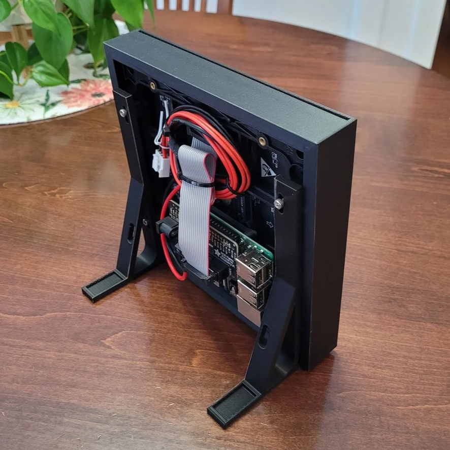
This custom enclosure for a 64×64 RGB LED matrix by [Davisan1001] not only provides a mount point for a Raspberry Pi, but presents a clean and smooth face with square pixels thanks to a 3D-printed grid, some parchment paper, and a sheet of clear plastic.

The first clever thing in this design is the way [Davisan1001] created the grid that acts as a light blocker for each LED in the matrix, preventing light from “spilling” over into its neighbors. Instead of designing the grid from scratch, the solution was just to leverage slicer settings. By printing a flat square with a grid pattern infill and zero solid top and bottom layers, the slicer creates the grid all by itself. A little trial and error was required to get the spacing just right, but it seems to have worked out fine. We’re not sure it’s better than designing a grid in CAD, but it was certainly a clever way to avoid having to do so.

[Davisan1001] also struggled to find an effective and economical solution for a diffuser. Certainly, high-quality diffuser films are available for sale, as are specialty acrylic sheets, but surely there was some household DIY option to do the trick. A sheet of plain white paper blocks too much light. Wax paper handles poorly, and off-angle viewing is poor. The sweet spot was parchment paper.

Parchment paper is commonly used in baking and is thin, easy to handle, flat and even in color, and just opaque enough to act as an effective diffuser while still transmitting enough light to not impede clarity. Cover the LED matrix with the 3D-printed grid, lay parchment paper over that, cover with a sheet of clear plastic, and the job is done.

Light diffusion can be tricky to get just right in a DIY project, and what works for one application won’t necessarily work for another. Our community had loads of suggestions on different solutions, so consider this one more idea to try the next time you have a project that calls for it.

3D Printed Cubes Provide Passive Cooling

4 September 2026 at 11:30

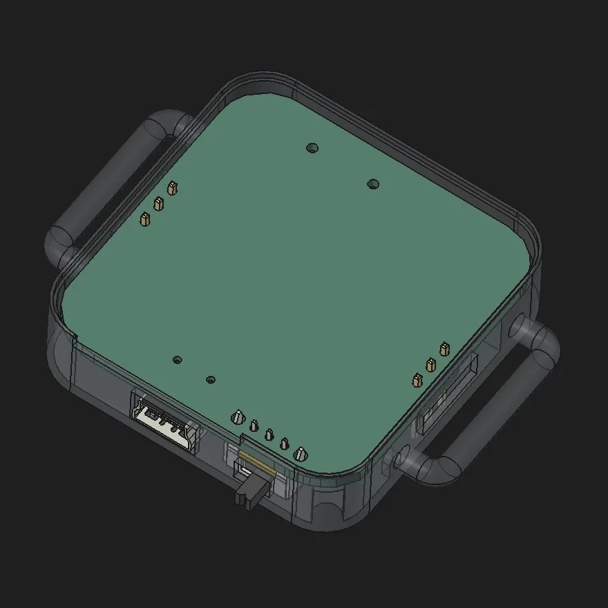
Passive evaporative cooling has been used for centuries to reduce temperatures. Heat is drawn off as water evaporates, which in turn reduces temperature. The more efficiently this process happens the greater the temperature differential, and that’s exactly what the 3D-printed structure pictured above aims for. Created at the Graz University of Technology in Austria, the cubes noticeably reduce surrounding air temperature thanks to their careful construction. As long as they’re kept wet, anyway.

The key is exposing the maximum amount of water to the maximum amount of airflow, and there are two ways the prototype cooling wall — which is 3D printed from a special clay mixture — does this.

First, the macro design of the 3D-printed blocks maximizes surface area. If the cube in the image above looks familiar, that’s because it’s the gyroid infill pattern. Gyroid is a porous pattern with no “dead ends” or closed sections, and the fact that it 3D prints cleanly with no supports also makes it an ideal structural candidate.

The second advantage is the clay used for the blocks themselves. Firing clay at a low temperature keeps it porous, but this particular mixture goes even further. It’s a bio-inspired formulation of clay, fungal mycelium, and wood chips. After printing, the cubes are fired and the fungus and wood chips burn away, leaving a network of thread-like capillaries with occasional larger pockets throughout.

The result is a porous ceramic cube with a massive evaporative surface area relative to its size. A practical test in a hot attic showed the air near a water-laden cube was nearly 7º C lower, a noticeable difference.

A home experimenter might not have access to fancy mycelium-laced clay mixtures, but it still strikes us as something that could be tried out at home. After all, clever hackers have successfully made DIY versions of passive cooling paint.

Take Tool Photo, Generate Custom Gridfinity Bin

4 September 2026 at 07:00

What if the organization and storage benefits of tool shadowing could be had and improved with a modular, semi-automated process? Tracefinity attempts that by generating custom Gridfinity bins from photos of tools, and has quite a few nifty features that are worth a look.

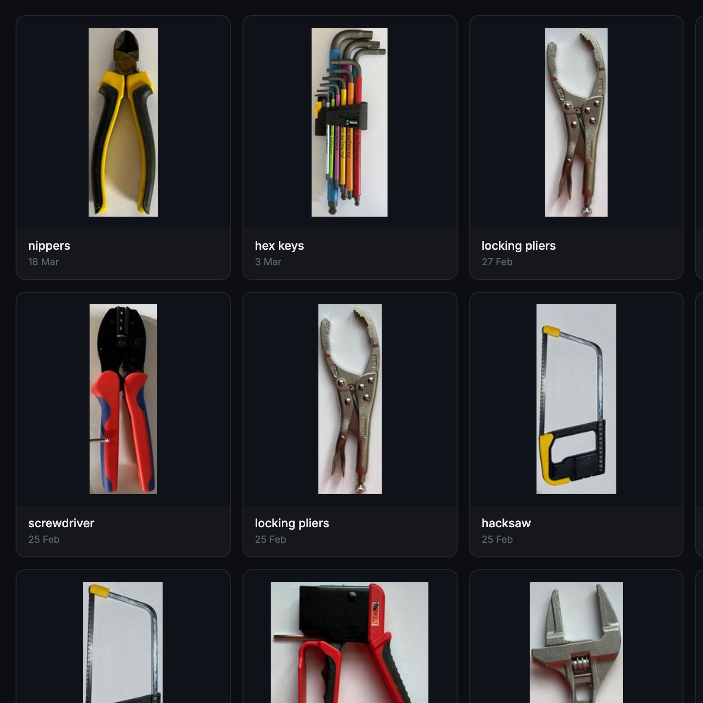
Maintaining a library of tools makes it easy to create project-based custom layouts.

The basic workflow is this: place one or more tools on a sheet of paper, take a photo, then upload the photo and have the system trace and save the outline and add it to a private tool library. When one is ready to create some bins, use the library of saved tool outlines to generate custom Gridfinity layouts.

If you’re unfamiliar, Gridfinity is a modular system of standardized bins and baseplates designed with 3D printing in mind, making it an ideal match for highly-customized organization tasks and a particularly natural fit for a tool-tracing system like this one.

The idea of taking a photo of a tool and generating a custom bin is a compelling one, and a couple years ago we covered a project that did just that. Tracefinity seems like a natural evolution of the idea, and includes handy features like easy design adjustments, optional magnet holes, and we really like the concept of a tool library from which individual tools are scanned once then later selected to create specific, project-based layouts.

Tracefinity takes advantage of new software capabilities like machine learning to improve and streamline the tracing process, but that doesn’t mean it relies on any external services. It can be entirely self-hosted and by default uses a local, CPU-friendly object detection model for tool tracing. There is an option to provide a API key to use Google Gemini instead, but it’s not required. It can come in handy for especially complex tool outlines or dealing with non-ideal source photos, however.

Corners Lifting On 3D Prints? Guide Gives Prevention Tips

3 September 2026 at 22:00

Large prints have a risk of warping, by which we mean corners can lift off the print bed as the object sort of curls inward on itself. It’s not always due to poor filament quality or an unclean build plate. Sound like something you’ve dealt with? Check out this handy roundup to understand why it happens, and learn ways to prevent it.

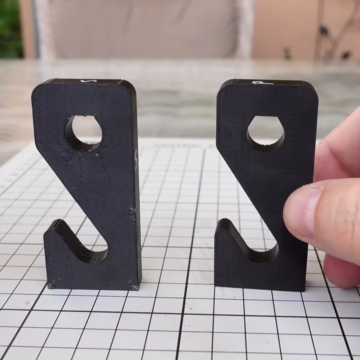
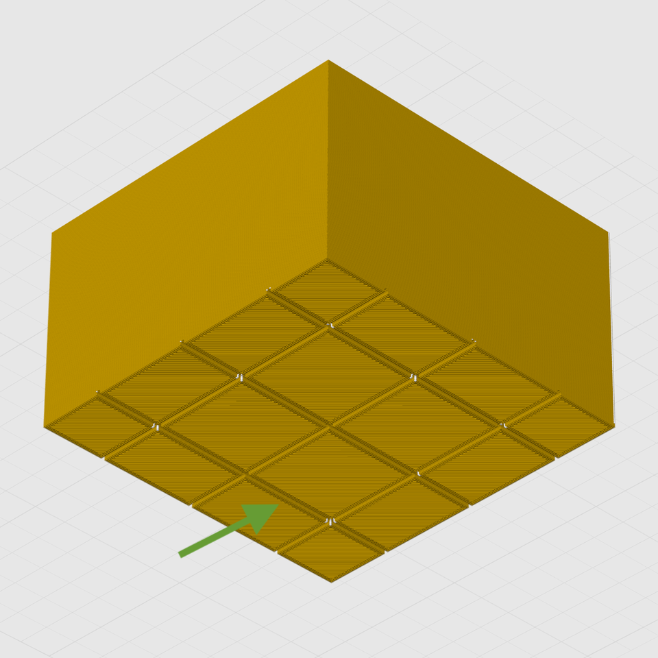
A big flat area with sharp corners is susceptible to warping. Breaking the footprint into a grid pattern helps distribute stresses instead of concentrating them at the corners.

The reason some objects have trouble while others don’t is physics. Deposited plastic shrinks ever so slightly as it cools, and some shapes — like wide, flat surfaces with sharp corners — are worse for this than others. This sort of problem is what the guide addresses with a number of techniques.

Some are simple, like turning on brims which increases an object’s footprint. This increased surface area offers more adhesion, but also increases heat transfer from the print bed into the model, slowing the cooling process. Thinner walls and an altered infill pattern is another option. Other techniques are more complex.

The most effective methods involve modifying the model itself to reduce or eliminate stress points. One such method is to break the model’s footprint into multiple zones with a shallow grid. Instead of one big flat bottom, the object has multiple smaller ones. Because big flat areas are more susceptible to warping than small ones, turning the bottom into a grid pattern helps spread those stresses out and prevent lifting.

If you design your own models, you’ll find several design tips worth keeping in mind. It’s always smart to practice good DFM (Design For Manufacturability) which means taking 3D printer strengths and weaknesses into account when designing an object. In this case, it can help prevent print failures. Good DFM can also make parts much, much stronger just by designing in the right features.

Reactive Heat and Wind Come to VR, Thanks to Smart Plugs

1 September 2026 at 14:30

Want to feel the heat of nearby fire, explosions, or radiation? Or even just the gentle warmth and breeze of a sunny day in the wasteland? If you said yes, you’re in luck because [GingasVR] created an immersive heat mod and wind mod for the VR version of Fallout 4 that leverages economical smart outlets and game scripting to do just that.

The heart of this hack lies in gluing two things that don’t normally go together. In this case [GingasVR] uses a bit of game scripting to control TP-Link HS100 or HS110 Smart Plugs, allowing virtual events to control things in the real world. An ordinary fan in a smart plug creates wind on demand, and heat comes from a 250 watt infrared heat lamp aimed toward the player. For heat, an IR lamp is the way to go because it’s highly directional, can be quickly cycled on and off, and responds rapidly.

The range of immersive effects opened up by this is pretty compelling. Sunny weather yields a gentle glow of warmth, but nearby explosions cause a short full-blast flash of heat. The heat of fires also grows and fades with proximity. This being Fallout, [GingasVR] ensured local radiation has an effect on the heat level as well. Want to see it in action? She briefly explains around the 3:20 mark in this video.

Using ordinary appliances and smart plugs controlled from within VR to modify environmental effects is clever, and we like that it’s entirely nondestructive. The scripting mod for the game doesn’t overwrite any game files, and the hardware used requires no modifications.

Not into Fallout? [GingasVR] has similar Skyrim VR mod, if that’s more your bag. And if you’re modding Skyrim VR anyway, consider adding a “meditation device” headband to make magic respond to your actual state of mind.

Low(er)-Cost Humanoid Robot Leverages DIY Actuators

30 August 2026 at 10:00

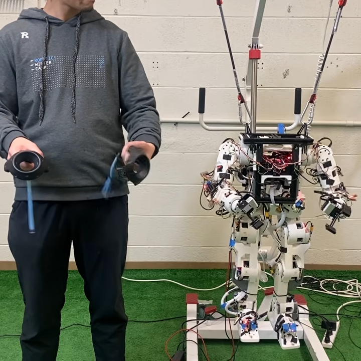
Humanoid robots, even scaled-down ones, tend to be expensive. The Berkeley Humanoid Lite offers a more accessible and economical option by centering the design around 3D printed actuators that make up the bulk of the robot’s frame.

The actuators are made by combining motors with printed cycloidal gearboxes and an embedded magnetic encoder. They’re modular, so even if one has no desire to recreate the whole robot it might be worth checking out the actuator design details to see if they might be useful in some other way.

The Berkeley Humanoid Lite isn’t a finished product so much as an open-source, easily customized reference design. The GitHub repository contains everything one might need, and you can watch some basic demonstrations, including VR-driven teleoperation, in the video embedded below.

At a total hardware cost of under $5,000 USD it’s still expensive, but much more economical than other humanoid robots, open-source or not. As mentioned, even if one doesn’t plan to build one, the modular actuator design is worth keeping in mind for other purposes.

Compact PCB Vise Uses Up That Leftover Filament

29 August 2026 at 19:00

Needing less than 70 grams of filament, [Chefkoch]’s 3D printed PCB vise solder station might be a good way to use up some filament spool leftovers and get yourself a handy tool in return.

What we like about this design is that it is multi-functional, and cleverly uses the solder spool as a counterweight to add stability that might otherwise be lacking in such a compact design.

The assembly can be reconfigured so that the jaws are either horizontal or vertical; the solder spool is held conveniently either way. The whole thing is 3D printed, so there’s no other hardware or fasteners involved. It’s probably best suited to small boards, but it’s also compact, entirely 3D printed, and doesn’t need much filament.

Still have some filament left over and want a nifty solder feeder to go with it? Check out the solder scroll, a pen-like DIY tool that makes handheld solder feeding a little less of a hassle.

Cheap AI Token Resellers: The Secret Ingredient is Fraud

25 August 2026 at 22:00

[Matt Lenhard] has an interesting writeup explaining exactly how fraudsters offer access to cutting-edge AI models at a tenth of the price. Perhaps unsurprisingly, the secret is to get tokens for free from anywhere they can and by any means necessary. Then wrap them in a pretty relay API, and sell access to it.

Relaying tokens is not by itself a shady practice. That distinction belongs to services that obtain tokens fraudulently, opening the door to selling them at rates far below market value. This practice is widespread and profitable, in part because the abuse is so hard to pin down and stop.

One source of tokens is free credits on new accounts. New accounts are spooled up as fast as possible, hammered until they’re empty, then it’s done all over again. Another method is to sign up as pay-after, possibly with a stolen card, and simply ensure the account has no valid payment method once the bill comes due. Or set up a temporary card, pay some minimum up front and consume as much as possible, then initiate a chargeback. It doesn’t matter if individually each of these doesn’t amount to much before they get flagged, because it’s being leveraged relentlessly on a massive scale by automated systems.

There are the shadier methods, too. Fraudsters don’t just target providers directly. Consumer software products with AI features get reverse-engineered, then the back ends hammered for all they are worth. Poorly-coded support chatbots can be highjacked into serving fraudsters’ traffic instead of just their own. It doesn’t actually matter where the tokens come from, after all. As long as the fraudsters are obtaining them for free (or at least below their costs) then it’s profit.

That last point is one [Matt] zeroes in on with advice on how to mitigate this abuse. He goes into detail in his writeup but what it comes down to is recognizing that it’s a numbers game. Fraudsters depend entirely on obtaining tokens for free, or nearly free. So just like using an AI to keep phone scammers tied up, anything that raises friction increases the fraudster’s costs, in turn encouraging them to find an easier target.

Quest VR Headset Becomes Unlocked Hardware

25 August 2026 at 07:00

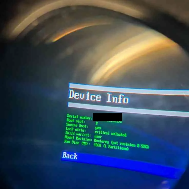
The Quest virtual reality headset gets a fully unlocked bootloader thanks to the QuestStack tool, which automates a complex process of privilege escalation to provide stable, privileged access to the hardware. This solidly frees the headset from its existence as a device tied to Meta’s walled garden, although the tool only works on the Quest 1.

Image credit: notmastergamerok on Reddit

Not simple enough? No problem, there’s also a web version by [darknight1050] that makes the unlock process as simple as plug in headset, visit web page, receive unlocked bootloader.

The first-generation Quest headset is an older (released in 2019) piece of hardware that is still perfectly capable, although it has been surpassed by later models in terms of performance and optics.

It has also been essentially forgotten as far as parent company Meta is concerned, with no requirement for new content to be compatible with it, nor consideration in general given to the device for some time now.

Hardware that is no longer supported should be opened. The Oculus Go got an official unlocked OS build which was a positive thing, but the Go was also a pretty limited device. The Quest 1 — the ‘Oculus’ part of the name having been dropped around the time Facebook renamed itself to ‘Meta’ — is considerably more capable than the Go was. Now people can have privileged access to its hardware, which may help save some of them from junk piles while enabling folks to do as they please with the hardware they purchased.

Straight Talk on 3D Printing Footwear At Home

25 August 2026 at 01:00

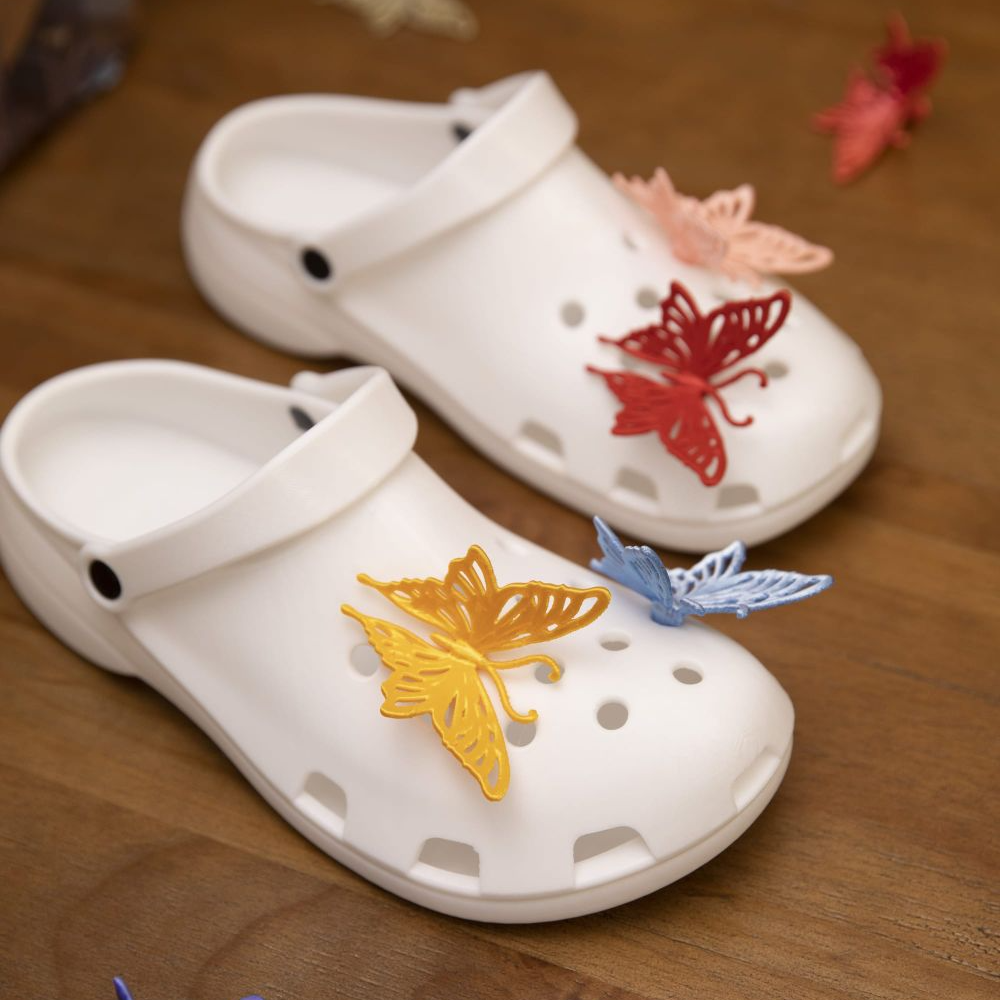
Printed footwear is an intriguing idea, but as far as projects go it is somewhat more complex than it first appears. This guide to 3D printing your own clogs not only provides a solid process, but also acts as a list of the challenges and pitfalls involved. After all, a piece of footwear is actually a fairly large object. Failed prints can be costly and time-consuming, so a guide like this is a valuable resource.

First of all, a 3D printer that can handle multi-material printing is called for. The footwear itself will be printed in TPU 90A as a sweet spot for hardness, but the print will require supports and those supports will need to peel away cleanly. The solution is a shoe printed in TPU with a rigid support structure of PLA. Using two different materials in the same print with anything remotely resembling efficiency calls for either a dual-nozzle print head, or a multi-toolhead printer.

3D printing one’s own clogs can be rewarding, if not necessarily cost-effective.

Here we want to take a moment and say that while the guide itself suggests PETG is also a suitable support structure, we suspect this might only be true for the exact filament formulations used in the guide. The safer approach is to use PLA. Why? As we’ve seen in other tests, PETG has been observed to stick extremely well to flex filaments in general, whereas PLA doesn’t really want to stick to anything other than PLA. The exact formulations of TPU and PETG used in the guide might be compatible with one another, but in general we recommend sticking to PLA as a rigid support for flexible filament.

Assuming a capable printer and suitable materials are nailed down, one also needs to worry about keeping the TPU dry. It is very sensitive to moisture, which directly affects print quality. You’ll also need to dial in the settings — a gyroid-patterned infill of 15% provides the right amount of “squish”, which is most effectively fine-tuned by changing the infill pattern rather than the density.

Is it worth the time and effort and filament cost to print one’s own pair of slip-ons versus simply buying a pair of Crocs®? Maybe not, but it can still be rewarding and this guide will help minimize any failed prints in the process. And if you do get a nice print but the TPU is sticking a little too well to the build plate, reach for the isopropyl alcohol.

Teardown Shows Low-Fi Microphone is Surprisingly Sophisticated

20 August 2026 at 07:00

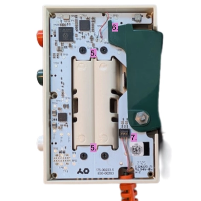
The Ting FX EP-2350 by Teenage Engineering is a standalone microphone with a few extras, including samples and built-in effect presets that can be modified by the user. It also has a distinctive design, and [Sam Holland] does an in-depth teardown that offers some insights that are worth keeping in one’s back pocket. The large, side-mounted lever in particular is an interesting bit, but more about that in a moment.

Inside the device is a single PCB, which has a cutout in the middle for a pair of AAA cells. A Raspberry Pi 2350 drives the device’s functions, supported by various components which [Sam] identifies, although he mostly looks at everything from the perspective of a mechanical engineer as he critiques the design. It’s a clean-looking, intentionally low-fi design that belies how complex the device really is.

The multi-function, chunky, spring-loaded side lever is of particular interest. It has three sensors: two switches and a potentiometer. One switch detects when the lever is at rest, or depressed by any amount at all. The potentiometer mates with the pivot point of the lever, allowing the device to directly sense how far the lever is pushed. The last switch triggers when the lever is pushed all the way in. Together, it forms an intuitive input that combines powering on (the device wakes up from sleep mode as soon as the lever is pressed) with the ability to adjust effects in proportion with how far the lever is pressed, while also bottoming out with a distinct click that itself acts as an input signal.

One other interesting bit is the light pipes that carry light from multiple indicator LEDs to the outside of the device. A textured surface acts as a diffuser and helps the lit surface look smooth, while a coating of silver paint prevents light bleed and (probably) maximizes light transmission through the plastic. Hot glue makes a pretty good light pipe material but if DIY light pipes end up in your next project, sanding the exit surface and giving the rest a coating of silver paint just might be worth a shot.

Watch Soldering Up Close and From Any Angle, in VR

18 August 2026 at 07:00

A manual skill like soldering is so much easier to learn and grasp when one can watch it in action, and there’s a brand new way to do that using virtual reality (VR). It isn’t just a series of 3D videos shot at someone’s workbench, either.

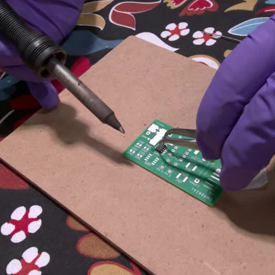
See soldering in action from any angle, with fine details preserved even close up.

PCB Hand-Soldering Basics is a series of thirteen videos that demonstrate soldering using Gaussian splats, a method of displaying 3D content that allows the viewer to freely look at things from any angle. Gaussian splats aren’t new, but what makes this different is the sheer level of detail and the fact that it’s focused on handheld tool use rather than displaying a famous location, landmark, or something similarly “big”.

Throughout the videos fine detail on the iron, parts, and the PCB itself remain visible from any angle and even from close up. Here’s a short video captured from within a VR headset that is probably the next best thing to seeing it yourself.

An educational production, it was was made in cooperation with the Department of Electrical and Electronic Engineering at Imperial College London. A few more details are in a LinkedIn post by [Tanmay Lad], who was part of the team involved in the production. The goal is to offer a unique, front-row seat to hand soldering with the ability to zoom in or look at it in 3D from any angle.

Not familiar with Gaussian splats? We’ve previously covered a great overview. They look great and are computationally cheap to render, and being able to get up close and see such detail is not really something one expects.

❌
❌