It is a classic Hackaday situation. You have an Egret GT E-scooter. It has a screen that shows the usual dash stats, but that led to an annoyance. You could accidentally enter firmware update mode and, from there, enter operational mode without the security PIN. [Ben] couldn’t let that stand, so he reverse-engineered the protocol and rewrote the firmware in Rust. As he put it, “… because I have to break… everything I own…” We get it.
The mobile app was useful for some basic info, since sniffing Bluetooth is fairly easy and analyzing mobile code is, more or less, straightforward. Analysis revealed some data that doesn’t show on the display and that several things are sent back to home base tagged with the scooter’s unique ID — another reason to gut the existing firmware.
Internally, the scooter uses the CAN Bus, so out came the oscilloscope and a homebrew CAN decoder. Surprisingly, the CAN bus is accessible on the USB-C port’s data pins. Officially, the port is only for charging phones, so you have to wonder what your phone makes of the alien signals on the data pins when it is charging.
Firmware updates actually come in at least three flavors: display, input panel, and main controller. Reverse engineering the firmware update process was crucial to installing the new firmware.
If you own a similar scooter, this post is a goldmine. If you don’t, it is still a very detailed breakdown of a reverse-engineering workflow, and you can apply many of the tools and techniques to your next project.
Of course, another option is to just keep the scooter and replace the brains. If you want to learn more about reverse engineering, there are literally dozens of Hackaday posts to help you get started.
During his continuing analysis of the architecture and microcode of Intel’s highly influential 8087 floating point unit (FPU) co-processor, [Ken Shirriff] has now arrived at the point where he can put together how the 8087’s microcode implements various x87 instructions. One of these, the FSCALE instruction turned out to be far more complicated than assumed, with one might assume to be a straightforward powers-of-two scaling turning out to entail over 140 micro-instructions and three levels of sub-routine calls just to handle all cases.
The annotated die shot in the heading image shows the functional blocks that are used by this one x87 instruction, to give some kind of idea of what amount of hardware even ‘just’ scaling a floating point number involves.
Much like with the x86’s CISC-style ISA, these 8087 instructions break down into individual steps that involve everything from loading values into registers, performing operations, checking for and handling error conditions as well as stack management. As can be seen in [Ken]’s breakdown of the FSCALE implementation in the 8087 it’s all very logical, taking a high-level instruction and doing all that’s needed for a robust implementation, without bothering the developer with the details.
Of note is that the 8087’s implementations led to the IEEE 754 floating point standard, providing what definitely at the time was one of the most mathematically accurate FPUs that somehow still was financially responsible enough to make it into a relatively affordable PC.
The Philips PM5139 is not famous. It won no great victories on the battlefield, nor was instrumental in changing the political landscape. It was just a useful function generator that you might find on a workbench somewhere, doing its job quietly and relatively accurately. [doctormord] has been doing the work to reverse engineer this humble piece of hardware.
The PM5139 is poorly documented; the only existing service manual out there is for the PM5138A, a less-capable sister model. Hence, there was some value in reverse engineering the device to understand it better. Work started with two EPROM dumps capturing what Philips put in the box all the way back in the early 1990s. From there, the code was examined and tinkered with until [doctormord] felt confident to modify it and improve upon what was already there. This was achieved with the aid of an 8051 emulator that could run the code to make it obvious what was going on. The result was a custom “V2.0” firmware that adds six arbitrary waveforms to the function generator and the ability to play simple music, amongst other tweaks.
The NEC V20 is an Intel 8088-compatible processor that features the same use of microcode, though with its own characteristics. This makes it important to use this same microcode if your goal is to create a cycle-accurate emulator of this processor, as [GloriousCow]’s goal is. Cue decoding the microcode ROM in a die shot of this CPU, in order to create a usable ROM image.
As with any fabricated ROM you can technically do it by hand, the ROM section in the die shot contained 29,928 bits which even at a pretty zippy pace would take up a considerable amount of time to parse. Here you can divide-and-conquer by handing parts of the ROM off to good friends, or you can use automation and some machine vision and theoretically get an answer as soon as you have finished writing and testing the tool.
Close-up of some of the microcode bits.
Although [Travis Goodspeed]’s MaskRomTool exists exactly to automate bit detection, it was found that there wasn’t enough contrast in the die shot for it to work reliably. What it did provide were the locations of the bits and from it 42×42 pixel PNG files of each bit.
Next a convolutional neural network (CNN) was trained to determine the difference between a 0 and 1 bit. This still took the manual classifying of 1,000 images, but seemed to work fairly well. Although some bits were marked as ambiguous, it was easy enough to use Mark 1 eyeballs to run a classification on these handful of images than to tweak the CNN model.
With this microcode in hand it was then possible to match it against the V20’s internal architecture to fully determine what each part does. Although not quite finished yet, there’s a GitHub repository containing the progress so far.
The V20’s microcode has been the focal point of much legal fighting back when NEC and Intel were still duking it out in how far one could make a CPU compatible with that of a competitor.
Like a lot of us [Liam Kloppers] had a problem with doomscrolling. Unwilling to go cold-turkey because he does find some utility in social media. He tried a number of things before deciding to say “Screw it” and just go full Pavlov on himself with some old-fashioned classical conditioning. Who needs willpower when you have electric shocks to dissuade you?
The key here was finding an electric-shock dog collar that could be controlled via a smartphone application, which meant he could reverse-engineer its Bluetooth protocol and get it linked up to his own software. The initial implementation ties his quick-and-dirty Python control program with a web server living on his laptop, which he’s configured MacroDroid to call on when his personal criterion for ‘doomscrolling’ is met.
With the shock collar wrapped around his leg, [Liam] was ready to test. It turns out dogs are a lot tougher than people, because even when set to a low level, the shock from the device made him toss his phone across the room and had him hesitant to even pick it up again.
Since he couldn’t bring himself to put the shock collar back onto his leg, he’s now thinking of an audible alarm, something we’ve seen work before. If you’re as unhappy with your habits as [Liam], perhaps consider a device like Commodore’s social-media-free phone before resorting to self-electrocution.
Earlier, we wrote an article on the issues that cars have. These issues are still common and car ransomware might soon emerge, hitting not just individual cars but entire fleets as vehicles get more autonomous and packed with different features.
In light of that, we want to show you a tool that makes car hacking more approachable. It’s GearGoat. The tool was built to simulate a car’s internal network so you can play with it.
GearGoat
GearGoat is a car simulator developed by INE Labs. It lets you work with the internal communication network used by most modern vehicles (CAN bus). Every action generates CAN packets on a virtual interface. You can use cansniffer, candump and UDS scanners with GearGoat, just like with any vehicle.
In a real car, you’d connect a CAN adapter (CANable or Macchina M2) into the OBD-II port, located under the dashboard. This port is basically a gateway into the vehicle’s internal network. Your system will treat the adapter as a network interface (can0) and you can start capturing and sending CAN messages. When someone presses the brake or turns on the indicators, it generates messages that travel across the network.
Setting Up
GearGoat runs inside a Docker container, so it’s easy to deploy. Clone the repository and run the script:
kali > git clone https://github.com/ine-labs/GearGoat.git
kali > cd GearGoat
kali > sudo chmod +x initial_setup.sh
kali > sudo ./initial_setup.sh
Then you need to configure the virtual CAN interface (vcan0):
kali > sudo chmod +x vcan_setup.sh
kali > sudo ./vcan_setup.sh
On certain distros you might be missing kernel modules. Here’s how you install them:
kali > sudo apt-get install -y linux-modules-extra-$(uname -r)
It doesn’t always work on Kali Linux though. You can manually load the required modules and create the interface yourself:
kali > sudo modprobe vcan
kali > sudo ip link add dev vcan0 type vcan
kali > sudo ip link set up vcan0
kali > ip link show vcan0
Now everything should be ready. You can start GearGoat:
kali > sudo docker run --network="host" --privileged geargoat
The simulator will be hosted on http://localhost. There you’ll see different car functions. Each button on the interface generates CAN traffic.
Intercepting Traffic
While the simulator’s running, it continuously generates CAN traffic. To see this traffic, use cansniffer.
kali > cansniffer -c vcan0
The output can feel overwhelming. The tool keeps highlighting changing bytes dynamically. It’s very noisy when you’re trying to establish a baseline. You need a way to tell the tool what normal looks like. Press Shift + 3 + Enter multiple times and cansniffer will treat the current state as the baseline. It won’t highlight the background noise anymore, so you’ll only see the changes you make.
Once the baseline is set, you can start playing with the simulator. Click the Left Indicator button and you’ll notice a change in the CAN data.
The first byte of a frame changes and it’s tied to 0x188. That means this identifier controls the indicator state.
When you play with the speedometer, you’ll see a different pattern. The changes happen in the 4th and 5th bytes are associated with 0x244. The speed climbs gradually.
Repeat this with other controls and you’ll see how functions map on the CAN bus.
Sending Input
Now we know which messages control specific functions, so we can interact with them.
To control the indicators, we’ll send CAN frames using cansend:
kali > cansend vcan0 188#0100000000000000  # left
kali > cansend vcan0 188#0200000000000000  # right
These commands will turn on the left and right indicators. The CAN bus runs at high speed, so these changes can be hard to catch. We used the watch command to make it more visible:
kali > watch -n 0.1 "cansend vcan0 188#0200000000000000"
Working with speed gets slightly more complex. Earlier, we found the address (0x244) and that specific bytes that control the value. To set a speed, we need to convert miles per hour into the format the CAN message expects.
To simulate a speed of 50 miles per hour you send:
kali > cansend vcan0 244#0000001F6F
You can see the simulator accelerating. Use the formula V = round(mph / 0.6213751 * 100) to calculate the value, then convert it into hexadecimal using big-endian.
Capturing and Replaying Traffic
You can also capture and replay traffic. That way you can record a sequence of actions and reproduce them.
To capture traffic, you use candump with logging:
kali > candump -l vcan0
It’ll record the CAN messages into a log file. Once captured, you can replay it:
kali > canplayer -I <log_file_name>.log
Summary
GearGoat can get you started with car hacking. You work with a simulated CAN bus to understand the communication patterns and message structure. It’s easy to set up and it’s not resource intensive, so it’ll run on pretty much any computer.
We also have our three-day Car Hacking training, showing you real attacks. It includes CAN protocol exploitation and the use of Software Defined Radio (SDR). There we show you how modern vehicles are actually compromised.
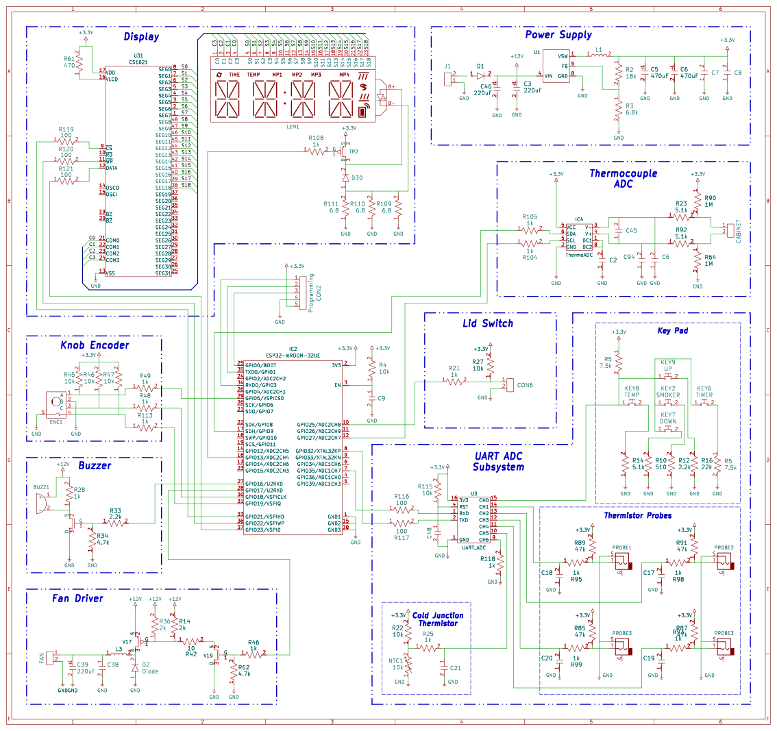
If you are a regular reader, then the odds are you have taken apart an electronic gadget, either for a fix, or simply because your curiosity got the better of you. Once inside, it’s all but impossible to help yourself from doing at least a little reverse engineering. That’s what happened when [PRBS23] took a look inside a MasterBuilt Gravity 800 Grill for a simple wire fix. But one thing led to the next, and now open source firmware for the grill is freely available!
The thermistor along with the physical inputs are connected to a 16 pin chip, interfacing with the MCU over a 9600 baud UART connection. [PRBS23] cannot determine an ADC chip meeting these specifications, so the most likely answer is a cheap MCU programmed to act as a simple analog fronted.
The neatly labeled programming header is used to quite easily dump the firmware with the espflash utility. Analyzing this dump reveals a rather strange ADC correction function used by the original firmware. The necessity and overall utility of this function remains unclear, does corrects a maximum of around 40 degrees Fahrenheit.
Most of the other features ended up being at least somewhat easier. The CS1621 segmented display driver is reasonably well documented with datasheets making its implementation far easier. Likewise, the other odds and ends were implemented in a far more normal manner compared to the thermistors.

 Login
Login