New navigation satellites in low-Earth orbit could provide 100 times stronger signal strength compared to GPS and other global navigation satellite systems operating from higher orbital altitudes—enabling greater location accuracy within dense cities, under thick foliage, and even inside buildings. Such signals would also likely prove more resilient to interference at a time when commercial flights, maritime shipping, and even various smartphone apps face increasingly widespread disruption from GPS jamming.
That vision may start to take shape when the first six production satellites of California-based Xona Space Systems are scheduled to launch in October 2026, with early service starting in 2027. Once the full constellation of 258 Pulsar satellites has been launched in the following years, Xona claims that customers will be able to accurately pinpoint their locations anywhere on Earth to within several centimeters.
“That added power means that we can get into that indoor environment that GPS can't get to today,” Adrien Perkins, co-founder and VP of engineering at Xona Space Systems, told Ars. “Our higher power allows you to get into those jamming environments a lot further than you would with GPS by itself.”
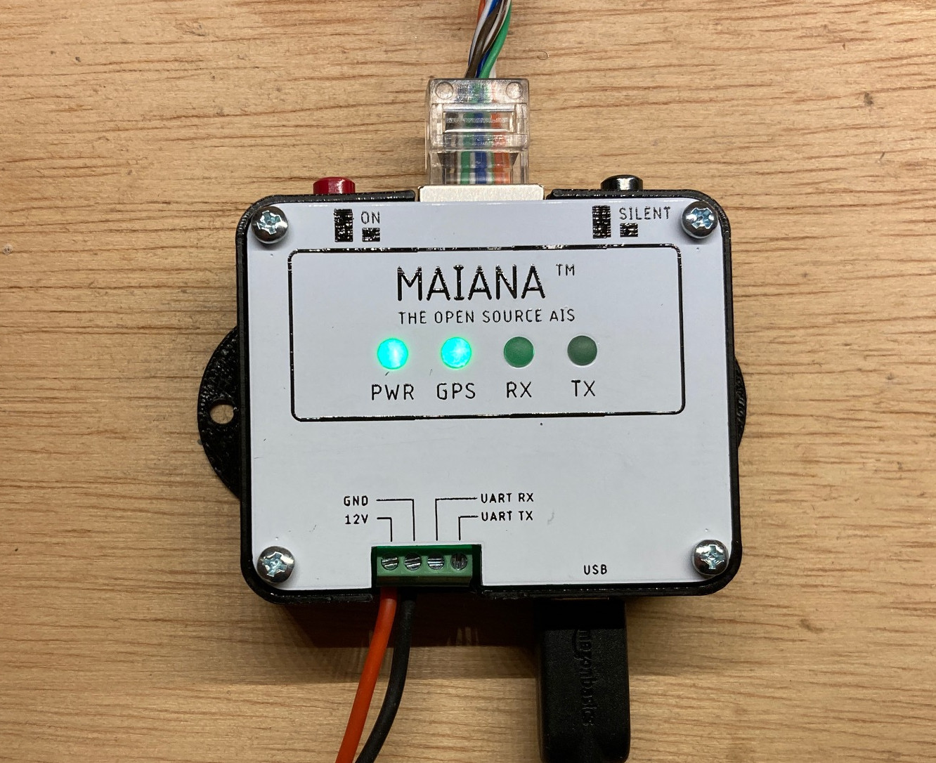
In order to not hit something, you generally need to know where that thing is. On land, the meager human eyesight tends to be sufficient. On the water, however, the prospects are more dangerous and complicated. So, technology is required to ensure safe ocean voyages in the form of the AIS transponder system. The off the shelf solutions tend to work quite well, but [peterantypas] was displeased with the commercial offerings, and built what appears to be the first open source AIS transponder called MAIANA.
Automatic Identification System (AIS) is a GPS tracking system designed for maritime applications. Broadly speaking, it broadcasts GPS and other data at intervals over VHF radio. AIS is what allows the precise tracking of vessels by authorities, and online hobbyists. AIS is also often received by other vessels to augment radar improving boat to boat collision safety.
Most commercial AIS transponders used by sailors are rather bulky, expensive, come with a large power budget. The MAIANA project avoids these pitfalls by being entirely self-contained. The RF portion is largely made up of a STM32L4 micro controller, a SI Labs Si4460 ISM RF chip, and a Quectel L76L-M33 with a Johansson ceramic chip antenna for GPS. With such simple hardware, the PCB is easily small enough to fit inside the antenna assembly.
This design eliminates the need for long runs of multiple shielded RF cables to a bulky transponder unit inside. Instead, a simple Ethernet cable is used to transfer data to and from the mast. Inside the boat, a USB decoder is used to pass the AIS data on to a PC. This whole setup is remarkably simple and reliable, with hundreds of units having been produced since the project’s start.
Every precision strike, every navigation-guided munition, and every soldier’s handheld GPS unit ultimately depends on a network of ground stations most Americans will never see, and the Space Force just handed Lockheed Martin $105 million to keep that invisible backbone working for the next generation of GPS satellites. The contract, awarded July 7, covers modifications […]
We’re all used to satellite navigation systems such as GPS or GLONASS, sheer magic in which the combination of a set of reference transmitters and super-accurate timing information can be used to calculate a position to an astounding precision. They had land based predecessors such as LORAN and Decca Navigator which worked in a similar fashion but with fixed land-based reference transmitters. Terra is an attempt to do the same thing without a network of dedicated transmitters, instead using FM broadcast transmitters as its fixed points.
This might seem like an impossible task without access to the transmitters, but they have a workaround using the Internet as a backhaul. Instead of transmitting their timing information like the systems mentioned above, they rely on a set of reference receivers sharing it online to the client’s receiver software. So far they have a demo running in Denver.
The interesting thing about this system is that it’s open-source, and requires only a relatively inexpensive software defined radio receiver and a computer to operate. Now anyone with a group of internet-connected friends to set up reference receivers can have their own positioning system, it’s no longer the exclusive preserve of governments. We like this idea, and we look forward to seeing it being tested more widely.
When you’re driving your car, you’re probably regularly looking at the speedometer to make sure you comply with the local speed limits. The method by which it works is simple enough: the rotation of the wheels is sent mechanically via a cable to a dial on the dash, or an electronic sensor counts the rotations of the drivetrain and an electronically-controlled needle or display shows the speed.
But what about if you were in an aircraft, and the wheels had nothing to do with how fast you were going? How would you even begin to measure speed? There are two ways: there’s a convenient solution to this problem rooted in simple fluid mechanics, and a far-more-complex modern solution. Today, we’ll explore how planes and helicopters are able to figure out how fast they’re going, by the old ways and the new.
Classical Methods
Measuring airspeed can be achieved by measuring stagnation pressure with a pitot tube, and comparing this to static pressure. This can be done at different points on the aircraft, or a pitot-static tube can be used, which measures both stagnation pressure and static pressure in a single probe. Credit: Chaos386, CC BY-SA 3.0
A key thing most aviators want to know is how fast their aircraft is going. Specifically, it’s nice to know how fast it’s moving relative to the airstream around it, which is referred to as airspeed. This is important, because it’s the aircraft’s velocity relative to the flow, such as wind, that determines the performance of the airfoils, how much lift is generated, and whether or not the aircraft is approaching a stall condition where it might fall out of the sky.
Bernoulli’s equation, rearranged to find airspeed (u), by subtracting static pressure from stagnation pressure, multiplying it by 2, dividing by fluid density, and taking the square root of that result.
Measuring airspeed is most commonly achieved with the use of a device called a Pitot tube. The pitot tube is a tube with a hole in one end that points directly into the airflow in the direction of travel of the aircraft.
As air flows in, it reaches a dead end and the flow slows to a stop, or stagnates, since it has nowhere to go. This allows a pressure sensor or a manometer or other device to measure the stagnation pressure at this point. The stagnation pressure measurement is related to the flowspeed of the incoming air since the kinetic energy of the flow is converted to pressure as the flow comes to a halt.
A secondary tube, pointing perpendicular to the airflow, is then used to measure the static pressure of the surrounding air, without the ram effect of the air being forced in by the aircraft’s forward motion. Then, it’s possible to calculate the velocity of the aircraft relative to the airstream by plugging the stagnation pressure and static pressure into a rearranged Bernoulli’s equation. If the pitot tube and static tube are hooked up to electronic sensors, the airspeed can be calculated electronically, and fed to a display or digital gauge.
A classic airspeed indicator has the pitot tube and static tube feeding right into the gauge in the cockpit. The pressure differential causes the diaphragm to expand as the airspeed increases, which mvoes a mechanism causing the needle to move on the gauge. Credit: FAA, public domain
Alternatively, it’s possible to effectively do this “calculation” mechanically. In earlier days, static and stagnation pressure captured by each tube would be fed to a gauge. Inside, the stagnation pressure would be fed to a diaphragm which moved due to the difference relative to the static pressure which is fed into the gauge body, and the movement of the diaphragm would, via a simple mechanism, shift the needle on the gauge.
A small General Aviation aircraft might mount a single pitot tube on the aircraft, feeding the air speed instrument in the cockpit. Commercial aircraft might mount two or more for safety’s sake, in case one becomes inoperable, while large airliners may have four or even more to provide a high level of redundancy and error checking. Heaters are commonly included on pitot tubes to ensure they can be kept free of ice, which can otherwise completely block a tube and make it impossible to obtain an airspeed reading.
Pitot tubes sticking out in the airstream underneath a Boeing 777-381. Credit: Cassiopeia sweet, public domain
For pilots, not knowing how fast (or slow) the aircraft is going can be highly dangerous, as it can lead to entering unstable flight regimes such as stall. Thus, it’s imperative that the pitot tubes remain unobstructed and functional for safe flight. Many aircraft accidents have occurred because of blocked or malfunctioning pitot tubes or airspeed instruments.
The New Way
Of course, you could fuss about with pitot tubes and pressure sensors and deicing measures, but that’s all very fiddly and old hat. There is an entirely different way to figure out a plane’s speed, though it’s only been available for the last few decades. It’s as simple as throwing a GNSS receiver on the aircraft.
Yes, whether your particular poison is GPS, Baidou, GLONASS, or Galileo, any major satellite navigation system will be able to tell you the speed of your receiver. Simply measuring the change in the receiver’s position over time is enough to calculate out the speed, and any off-the-shelf receiver will present this information as standard. It’s generally not used as a primary indicator in aircraft, because it reports ground speed, not airspeed, the latter being more relevant for aviation purposes. Still, it can prove to be a useful sense check when traditional airspeed indicators are non-operative or reporting confusing data, and GNSS devices are widely used on many aircraft today.
Flying High
Many modern aircraft have so-called “glass cockpit” displays that include feeds from GNSS receivers, which can provide supplementary data such as satellite-based ground speed measurements. However, these readings are generally not used for the primary task of flying the aircraft. Credit: Bluedisk, CC BY-SA 3.0
If you’ve ever wondered how an aircraft measures its speed as it floats through the amorphous gas cloud we call an atmosphere, now you know. Even to this day, where electronics and computer wizardry control our fanciest aircraft, airspeed measurements are still done with the same simple physics, just with some fancier sensors for help. The fundamentals haven’t changed at all. Now you know, you can always dig deeper into the many other rich applications of Bernoulli’s equation and fluid mechanics in general. Happy learning.

 Login
Login