Normal view

There are new articles available, click to refresh the page.
Before yesterdayMain stream

Hackaday Europe 2026: Outdoors with Robots

8 September 2026 at 11:35

Erin Kennedy has been building robots for over a decade now, with a focus on smaller bots that interact with, or maybe even clean up, the outdoor environment. Still other bots are made to interact with people, and when the people are outside in the park, that’s where your robot needs to go.

Whatever the reason, Erin’s talk at Hackaday Europe 2026 is an invitation to take your projects out into the outdoors. But the great wide world outside of your lab is not necessarily the most friendly place for a little bot, and the other half of this talk is about practical design tips and lessons learned to help it survive.

Environments

She structures the talk around different environments, which gives her an opportunity to focus on her bot cleaning up plastic trash on the beach, but also to point out the absolute horrors that sand can work on robot motors. She goes through a number of strategies for dealing with this, including going slow, keeping the motors as high up as you can, and designing the body of the robot to be full of holes and shed sand.

Taking to the water, she demos Otter Force One, which aims to capture invasive sea urchins. But underwater means under pressure, and she gives us some good tips on how to get the cables out while keeping the water in – double-o-ring cable glands potted with marine epoxy. I especially love the Nalgene-bottle-on-a-string with a radio that can be deployed to help retrieval. Her lessons-learned section is as deep as it is understated, including underwater hazards from low visibility to accumulated silt messing up your presumed center of gravity. Over the long term, rubber leaks and barnacles accumulate. Double seals, durable hooks, tether ropes, and bright colors are your friends. Underwater bots have it hard.

Erin’s air-inspired bots are the wildest. Some are just whimsical, like the flappy square bird, or beautiful like the butterfly bots. But her Atmosphinder bot uses the wind for actual propulsion. It’s a rolling wheel with sails that aims to explore long distances on Mars. Whether it’s going to get there or not, it’s got a bunch of great design elements for anything you have that’s going to have to roll. “Magic toboggans” make great plastic sails. But beware, while you can turn off a motor, you can’t turn off the wind. Be prepared to stake your bot down before or after its mission.

Experiences

Whatever the environmental challenges of taking your bot outside, it’s the non-laboratory environment that’s the most challenging, and rewarding. Erin tells the story of when a bird settled down in the shade cast by Bowie, or when the wind blew all of the Aruco markers away. But people and animals are just as delightful and unpredictable as the weather, and that’s an extra level of adventure. If you’re going far, bring hydration for the humans and spare batteries for the bots. Rolling with the changes seems to be the key to having a good time outside with your bots.

And of course, bringing your robot outside is a great opportunity to share what you’ve been working on with the offline world. We absolutely love the mission: normalizing robot hacks among the general public by hanging out with your bot in the park is right up our alley. She has had tremendous success with random encounters – folks just coming up and asking about what it’s doing. Making your bot seem friendly and/or beautiful seems to go a long way here. Don’t neglect the aesthetics.

Take Your Bot Outside

We left Erin’s talk absolutely inspired to build something that can make it through the rough environment that lies just outside our basement. It reminded us of our old days experimenting around with BEAM robotics, another bio-inspired practice aimed at the outdoors. With 3D printable parts and cheap geared motors, you don’t even have to break the bank to build your own Mars neighborhood rover. Watch this talk and get inspired!
Hackaday Europe 2026: The 1-Bit CPU That Ran Factories

19 August 2026 at 10:02

Powered machinery started the industrial revolution, and it was automation that kicked it up another notch in the 20th century. The ability for machines to make things by themselves spurred increased output and in turn boosted economic growth. The concept became widely popular for manufacturers to implement, as any change with serious economic benefit tends to do. Fast forward to today, and advanced robots and fancy machine vision systems running on powerful computers are the norm in modern factories which create the many wonderful products that we all purchase, use, and enjoy.

Once upon a time, though, things weren’t so sophisticated. [Nicola Cimmino] came to Hackaday Europe 2026 to tell us all about a remarkably simple 1-bit CPU that used to run factories.

Logic, But Make It Cheap!

Nicola Cimmino used to frequent a facility that used to recycle electronic waste, which sold old bits and pieces of hardware by the kilo. Many times, Nicola would pick up odd boards with an eye to repurposing components for future projects. Eventually, one unremarkable looking chip caught his attention—the Motorola MC14500B. This chip was rather unique, being a rather simple processor with just 16 instructions and a 1-bit data bus.

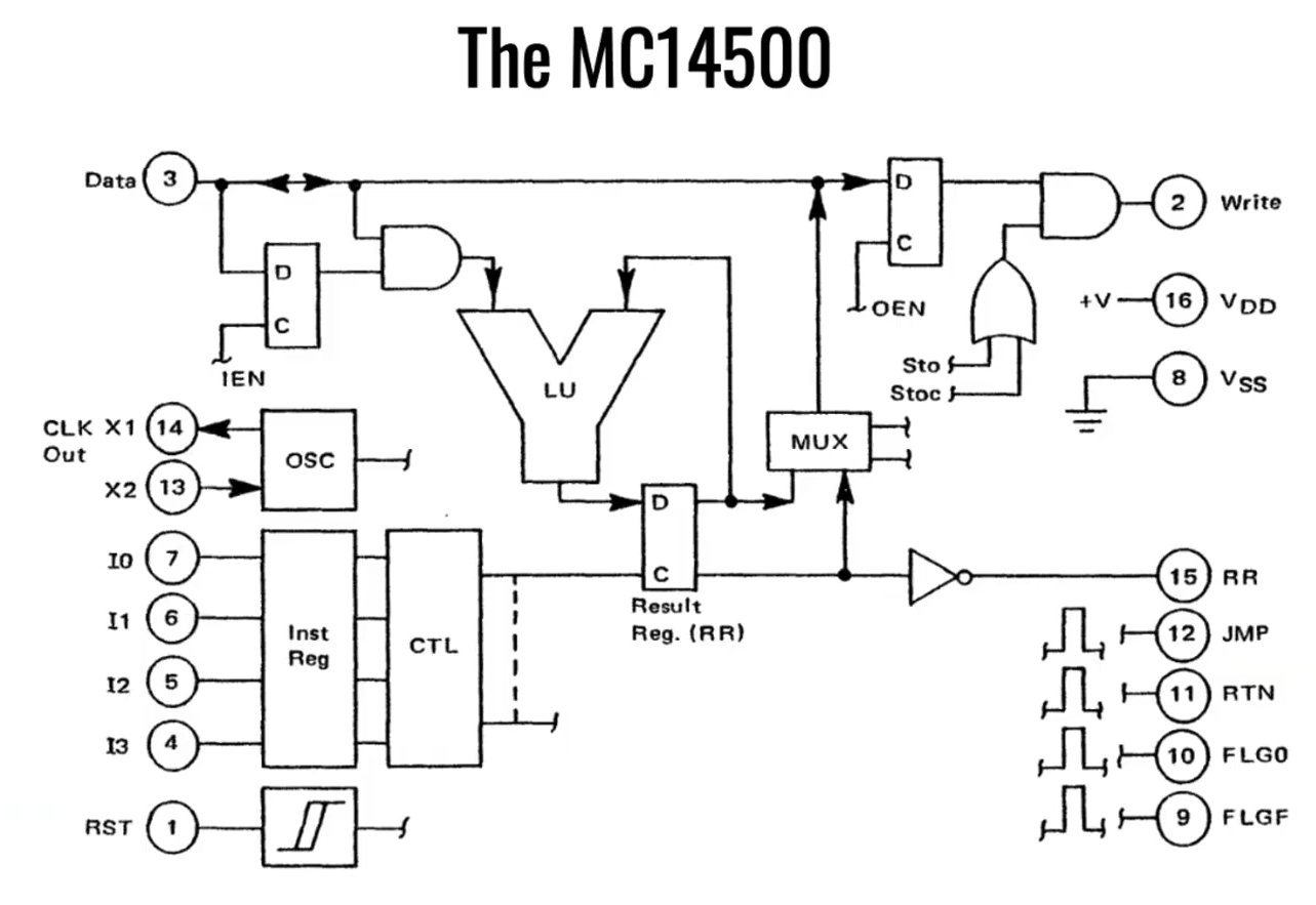
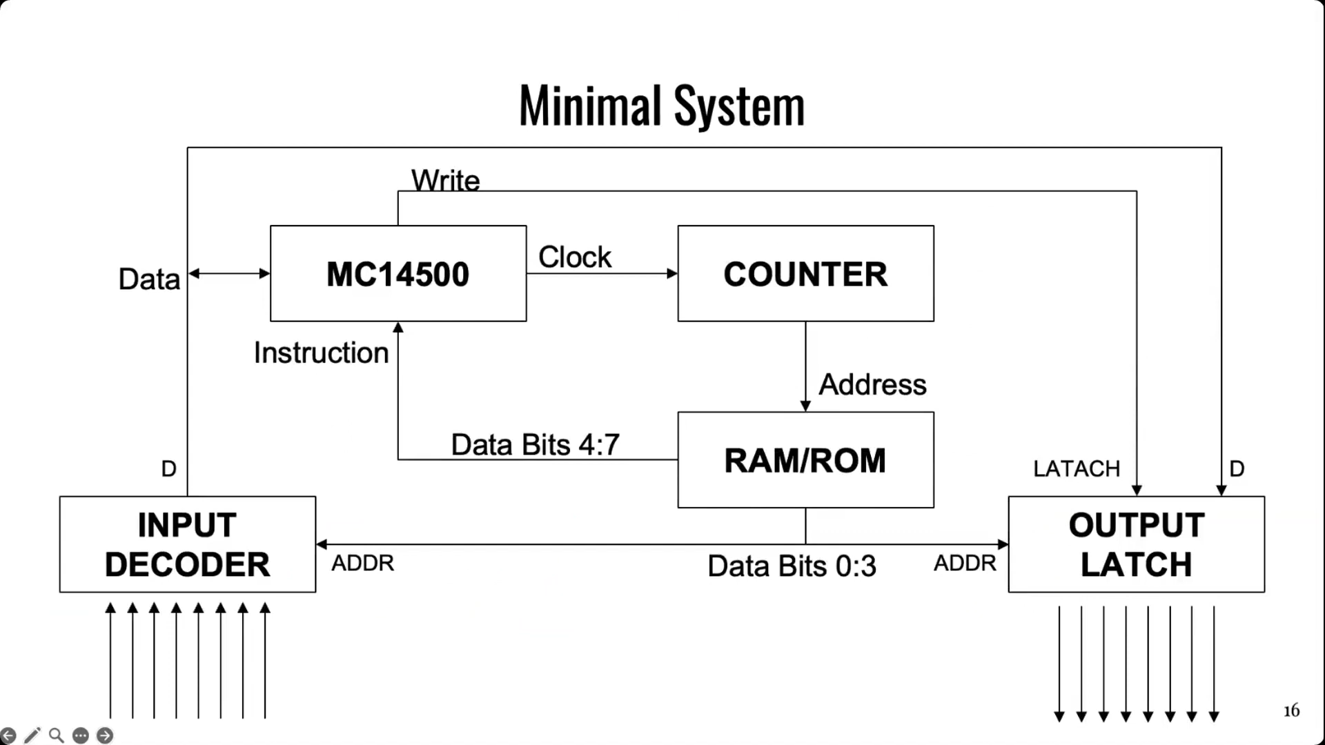
The simple architecture of Motorola’s basic 1-bit chip. Credit: talk slides

It’s worth examining the era in which this chip existed. Intel dropped the 4-bit 4004 in 1971, with the famous 8-bit 8080 landing in 1974. The Zilog Z80 came along in 1976, similarly an 8-bit design. And yet, when Motorola released the MC14500 in 1977, it landed with a rather slimline 1-bit design instead. Nicola notes that this likely came down to price, since populating a chip with more transistors cost more money quite significantly back in the 1970s. If the job could be done with less, it would make the part cheaper and thus more popular in the market. Bearing this out, Nicola explains that a 1976 Zilog Z80 used 8,500 transistors and cost around $200 USD, while an MC14500 used just 500 transistors and could be had in 1977 for the bargain price of just $5 USD.

It doesn’t take much supporting hardware to get an MC14500 up and running. Notably, though, there is no memory or program counter on board, so those have to be added externally. Credit: talk slides

Back in the mid-1970s, automation in industry often consisted of simple logic that was handled by cabinets full of relays. This took plenty of bulk, required hard-wiring everything, and also involved plenty of electromechanical parts that could wear out. Changing logic required manually rewiring things which could be fussy and tedious at the best of times. In those days, the Programmable Logic Controller was just coming into use, developed to be a reprogrammable system for industrial automation tasks that was more flexible and reconfigurable just by reprogramming it.

The MC14500 sprung up as a useful tool at this time, powering a great many programable industrial systems. It was designed to offer the bare minimum requirements for its application, while leaving extraneous hardware for designers to implement if and when it was needed. The architecture is simple enough for Nicola to explain with a single slide. The chip came with a 1-bit logic unit, operating with a result register, a 1-bit accumulator and the data bus. A minimal system could be lashed up with the MC14500, a counter, some external RAM or ROM (since none was onboard), and an input decoder and output latch of 8 bits each. This setup would only allow for doing combinational logic, since there is nowhere to store the current state of the system. However, hooking some outputs back to the inputs could allow for sequential logic, since it would allow for storing the current state of the system via those outputs. Nicola then steps through various other configurational changes to addressing and system architecture that could be made to optimize the MC14500 for use in different ways.

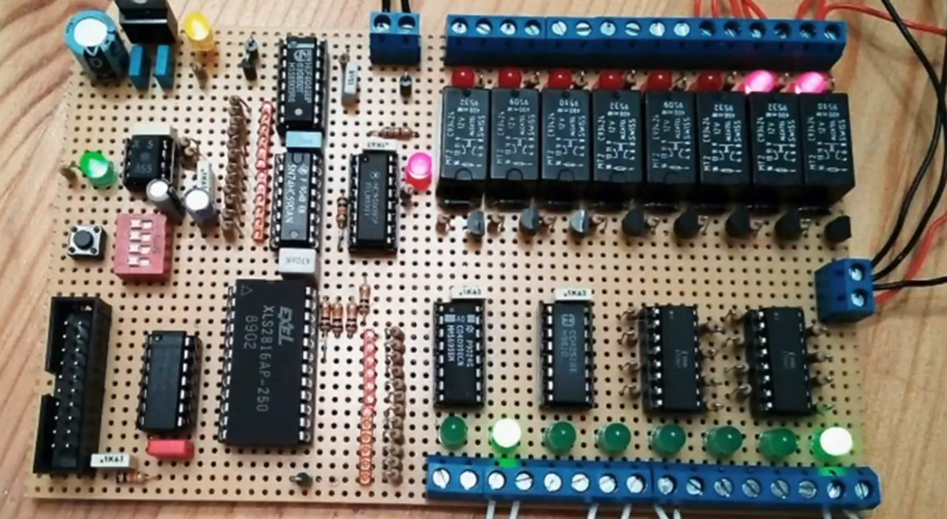
Nicola built a homebrew MC14500 system, allowing him to get to grips with the classic chip. Credit: talk slides
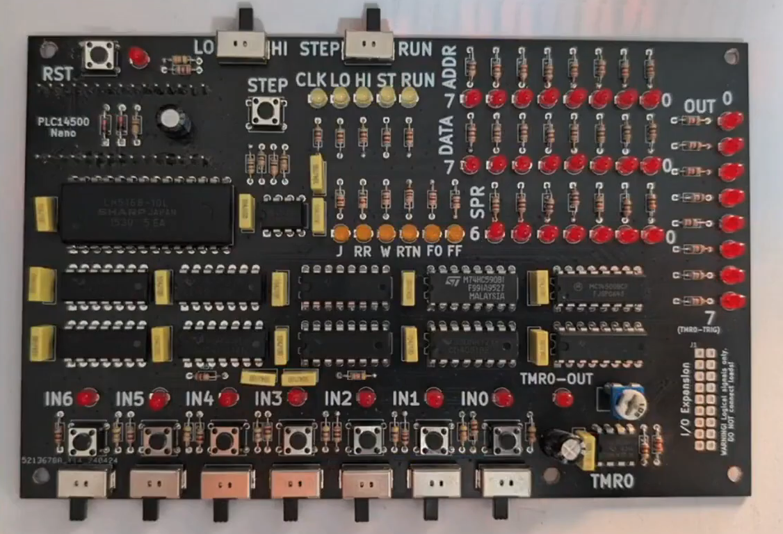
A more polished version came later, built on a custom PCB. Credit: talk slides

If you wanted to get to grips with using an MC14500 in industrial contexts, you would do well to pay attention to this talk, even if it came out some 40 years past the part’s heyday. Beyond the basic system architecture, Nicola explains how to use the limited instruction set, and how to get such a system executing simple programs in ladder logic, which remains somewhat of an industrial standard to this day. Beyond that, he steps up to more complex logic, like if/else conditionals and the use of some of the weirder instructions of the chip. He then shows off the hardware he built himself—both a breadboarded MC14500 setup built with wirewrap, and a more polished version on a custom PCB.

It’s not every day you get to learn about the nitty-gritty details of working with industrial hardware from the ground up. And yet, that’s exactly what Nicola brought to Hackaday Europe 2026. It’s an excellent primer on the topic, and also simply just good fun if you’re a fan of electronics and logic itself!

Hackaday Europe 2026: Open Source Hardware Goes Underground, Literally

By: Tom Nardi
17 August 2026 at 10:02

These days open source is everywhere, and frankly, we couldn’t be happier about it. But even with as prevalent as open software and hardware has become, we still occasionally hear about a project that takes the concept somewhere unexpected. Which is precisely why we were so eager to hear more about the fascinating work [Phil Underwood] has been doing.

In his talk Open Source Caving: 20 Years of Making Cave Mapping Tools at Hackaday Europe 2026, [Phil] takes us through a series of progressively more advanced open hardware devices that he’s designed to increase the speed and accuracy of underground mapping efforts. Along the way, he’s learned a number of valuable lessons about designing hardware that’s robust enough to handle the uniquely challenging environment underground while still being accessible enough for a hobbyist to build and use.

Improving on the Old School

It’s not much of a stretch to assume that most Hackaday readers haven’t spent a lot of time crawling through underground passages, and as such, may not be immediately aware of how one begins to map a cave in the first place. Helpfully [Phil] starts off his talk by explaining the traditional process — which generally involves a compass, an inclinometer, a tape measure, and plenty of intricate notes.

Once you’ve collected all that data and successfully returned to the surface with it, you can plug it into software and create a three dimensional map of the cave. Sprinkle in some surface topography, and you’ve got a pretty slick overview of whats above and below ground.

Like so many other cavers, [Phil] wanted a way to make that first half of the process a bit less tedious. He imagined an electronic device that could take at least some of the necessary measurements for him, but was limited by the technology and at-home production capabilities available to hobbyists in the early 2000s. There was also the cave environment to contend with: any piece of equipment used in a cave not only needs to be able to handle the dusty and cramped conditions,  but must be reasonable shock resistant. If that wasn’t tricky enough, there’s also a non-zero chance that it will need to spend some amount of time underwater.

Incremental Improvements

The first-generation of [Phil]’s surveying device. Undaunted, [Phil] put his first electronic caving aid together in 2008. Inside the off-the-shelf Radio Shack enclosure was an 8-bit PIC18LF2550, a dot-matrix display, an accelerometer, and a magnetometer. The data from the two sensors could be used to determine the heading and angle that the device was being held at, and while it still required the operator to manually take a distance measurement along that vector, having two-thirds of the information already computed saved considerable time and effort during surveys.

The first-generation of [Phil]’s surveying device.
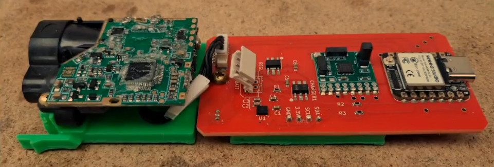
The next big technological leap came in 2020 — not just in terms of the device itself, but in the tools [Phil] had access to. This new device utilized a 32-bit microcontroller, a 3D printed frame, and included a laser rangefinder.

Thanks to the the increased computational capabilities offered by the modern MCU, more of the necessary calculations could be done on the device itself, which further sped up the surveying process. But [Phil] notes that the data from the laser module wasn’t always reliable, and keeping the more complex device protected from the elements introduced new challenges.

Now evolving at a faster clip, by 2023 [Phil] had improved on the design with a better integrated 3D printed case, custom silicone buttons, and a more polished user interface. At this point, he also switched over to writing the device’s firmware in CircuitPython. The lower bar of entry compared to C seemed to better resonate with those in the community, and consequently [Phil] started seeing more code contributions from outsiders.

New Dimension, New Challenges

By this point [Phil] had a pretty solid handheld device to assist in performing cave surveys, but the end result was ultimately the same as if the measurements had been taken manually. Each successive generation of the hardware made the process of gathering spatial data faster and less cumbersome, but didn’t meaningfully improve the final product.

Creating higher fidelity maps would require more data and the computational power to churn through it, which is why the latest generation of [Phil]’s hardware utilizes a Raspberry Pi 5 Compute Module and a pair of low-light cameras to perform photogrammetry. When combined with the heading and angle data, this produces a textured 3D model of the inside of the cave with minimal manual effort on the part of the user.

While this latest generation of hardware is undeniably more capable than what came before it, there’s an argument to be made that it also takes a step backwards in some respects. The cameras represent a physical weak point, and [Phil] says he’s still working on an approach to more adequately handle the increased power requirements of the Pi 5 Compute Module compared to the microcontrollers used in his earlier devices. But just as with the rest of the problems faced over the last two decades, these issues will likely be resolved in time as well.

In the end, this incremental approach to hardware development may be the most valuable lesson to take away from [Phil Underwood]’s talk. It’s a safe bet that the vast majority of those who view this presentation will never find themselves exploring an underground cave system, much less mapping one. But that doesn’t mean they can’t learn from his practical and methodical approach to building the right tool for the job.

❌
❌