The site of the Chornobyl Nuclear Power Plant (ChNPP) remains a unique location, as what’s left of the No. 4 reactor is the only place in the world where you can find significant amounts of what is called corium. An amalgamation of nuclear fuel, fuel rod cladding and whatever materials like concrete that the molten mass came into contact with, Soviet scientists initially struggled to make sense of this material, leading them to even have it shot at to get samples.
In this video documentary by [That Chernobyl Guy] these struggles by scientists both in and outside the USSR to comprehend this wholly new material are detailed. Much like trinitite – created by a US nuclear weapons test – these are amalgamations of material combined under extreme conditions. In the case of the ChNPP accident, the botched turbine spin-up test and disabling of all safeties by the operators allowed the bottom core chain reaction to run unconstrained, producing the massive steam explosion that flipped the biosafety lid of the RBMK reactor, while also fully melting the core material that then melted through the concrete below the reactor.
Although this Elephant’s Foot is only a tiny fraction of the total mass of corium inside the No. 4 reactor, it got rather infamous for supposedly being highly radioactive and lethal. In reality it’s one of the least dangerous parts of the exposed corium, and repeated sampling attempts along with internal degradation due to radioactive decay and weathering before the NSC shelter was installed have led to it mostly turning into slightly radioactive, rusty-looking dust at this point.
Also covered in the video is how the corium in the destroyed reactor is likely to be retrieved for final disposal, with robots cutting into the sides of the reactor building rather than trying to navigate destroyed corridors and staircases. This way it might be possible to remove most of the material without the issues that stymied Soviet engineers in the 1980s during their sampling attempts.
Over the centuries there have been an incredible number of purported medical devices released onto the market, with some having more outrageous claims than others. Released in the 1910s and produced into the 1920s, the Farador electrotherapeutic device claimed to be a thermoelectric device that would cure all disease conditions. In a recent video over at the [Our Own Devices] channel we get an in-depth look at this device and its usage instructions.
It’s a thermoelectric generator. Sort of. (Credit: Our Own Devices, YouTube)
On the Smithsonian’s website you can see the version they’ve got. It’s not identical, but the working principle remains the same — after bypassing the whole ‘is this the right treatment’ questionnaire because it’s a cure-all device, you take the main metal device and its connected electrodes out of the box.
Unlike similar devices of the era that applied an actual electrical current using batteries or similar, this Farador purportedly uses thermoelectric power generation, but there’s no clear hot or cold side to what would be the generator. Despite this, about 20-30 mV can be measured across the electrodes, so surely it’s working?
As it turns out, the Farador is just one of many fake medical devices that cloned the original Electropoise. Naturally such devices have been disassembled by many over the past decades, and as it turns out they are all empty inside, or at least devoid of any mechanisms. Much like many of such fake medical devices today, they mostly bank on the placebo effect. This placebo effect can be so strong that it’s even a confounding factor in real medical trials and medicine.
The more involved and complex the purported medical treatment seems, the stronger the effect tends to be. For the Farador the complex instructions, apparently high-tech thermoelectric generator and such all help to create the illusion and could thus be construed to be the main feature of this product.
Last time we found out the idea of space stations is surprisingly old. By the 1950s, everyone knew we’d be working in beautiful space stations that rotated like a wheel to give us the illusion of gravity. Of course, that didn’t happen. But we did get some practical space stations, even before the current crop. The road to get there, though, was predictably bumpy.
Convair: From TASSEL to MARS
Convair had been studying multi-person orbital stations under Krafft Ehricke since the late 1950s. One result was TASSEL, an acronym for the Three Astronaut Space System Experimental Laboratory. Proposed in 1960, TASSEL was a three-man laboratory intended for an Atlas-Centaur launch into a roughly 200-nautical-mile orbit and missions lasting two or three weeks.
Around the same time, the Air Force asked contractors for proposals for a Military Test Space Station, or MTSS. Convair was one of five companies selected for the study in 1960. The surviving record suggests that Convair’s TASSEL work fed directly into its MTSS proposal.
Then Convair did something unusual for an era overflowing with beautiful paintings of spacecraft that never existed: they built theirs. Well, sort of.
During late 1960 and early 1961, the company constructed a full-scale ground mockup called the Manned Astronomical Research Station, or MARS. The station itself was about ten feet in diameter and fourteen feet high, with two floors for working, cooking, housekeeping, and sanitary facilities. A Mercury-like reentry capsule beneath it brought the whole assembly to about 28 feet tall. You can see a contemporary video about the program below. There’s also a cache of photos and a post by [The Space Review] explaining it all.
MARS obviously wasn’t going to orbit, but that wasn’t the point. Engineers could use it to work on the less photogenic parts of putting people in orbit: life support, oxygen consumption, water regeneration, contaminant monitoring, controls, displays, and simply discovering whether people and equipment actually fit where the drawings said they would. Crews later spent as long as 30 hours inside the mockup.
Exactly where MARS fits among Convair’s various proposals is still being pieced together. Archival evidence indicates that it grew out of TASSEL and closely overlapped Convair’s submission for the Air Force MTSS program. Photographs in the San Diego Air and Space Museum archive are even identified as “MTSS/MARS.” Whatever name was on the proposal of the week, by 1961 Convair had progressed from drawing space stations to building a high-fidelity example on the ground.
Olympus and MOL
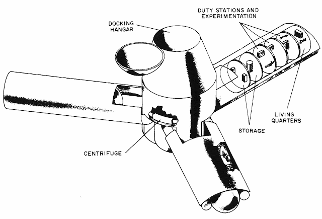
Olympus was nearly 140,000 pounds, 150 feet wide, and each arm provided 35,000 cubic feet (NASA).
NASA wasn’t far behind. In 1962, Edward Olling at the Manned Spacecraft Center proposed Project Olympus. It would have been an 18-person station intended for launch around 1966 or 1967. It wasn’t the classic doughnut. Instead, three long arms extended from a large central hub, and rotation would provide different artificial-gravity levels at different distances from the center. The station would orbit about 300 nautical miles above Earth.
This is especially interesting because Olympus wasn’t a far-future colony study. It was being considered while Mercury was still flying. Then President Kennedy gave NASA a somewhat more pressing assignment involving the Moon.
Olympus joined the large pile of spacecraft that looked great in presentations.
The U.S. Air Force had another station that got considerably closer to hardware: the Manned Orbiting Laboratory, or MOL. Approved in 1965, MOL would have put two military astronauts into a polar-orbiting station attached to a modified Gemini spacecraft (Gemini B). Its actual classified purpose was high-resolution reconnaissance. You can see some silent footage of some of the hardware in the video below.
They selected astronauts. They built hardware. They modified a Gemini capsule with the unnerving idea of putting a hatch through its heat shield so the crew could crawl into the laboratory behind it. MOL was canceled in 1969 without a crewed station ever flying.
Meanwhile, docking — one of the basic tricks required to make stations useful — was becoming real.
Dock of the Bay
On January 16, 1969, Soyuz 4 and Soyuz 5 docked in orbit. There was no pressurized tunnel connecting them. So Yevgeny Khrunov and Aleksei Yeliseyev put on spacesuits, climbed outside Soyuz 5, traveled across the docked spacecraft, and climbed into Soyuz 4. Two spacecraft had effectively become a tiny space station, but changing rooms required going outside.
Apollo 9 flew less than two months later and provides an interesting parallel. The command module and lunar module could dock, and crews could normally transfer internally. But what if the tunnel couldn’t be used? NASA planned to demonstrate a contingency EVA transfer from the lunar module to the command module.
Rusty Schweickart was supposed to perform the exercise, but space sickness caused NASA to shorten his EVA. He tested the lunar EVA suit and portable life-support backpack from the LM porch while Dave Scott partially exited the command module, but the complete external transfer was never performed.
Salyut and Almaz
On April 19, 1971, the Soviet Union launched Salyut 1, the first actual space station. The first crew failed to dock successfully. The second crew, Soyuz 11, spent more than three weeks aboard, but all three cosmonauts died during reentry when their Soyuz depressurized. There is some video from Salyut 1, but no audio.
The Salyut name also concealed a second program. Some of the stations were civilian Salyuts, while others were military Almaz reconnaissance stations similar in purpose to MOL. Salyut 2, 3, and 5 belonged to the Almaz line, although Salyut 2 failed before a crew could arrive.
Later Salyut stations gained a second docking port. That was a huge improvement because Progress cargo ships could bring supplies and fuel while a Soyuz remained attached as the crew’s ride home. Long-duration spaceflight was becoming practical rather than heroic improvisation. Of course, none of them rotated.
Skylab
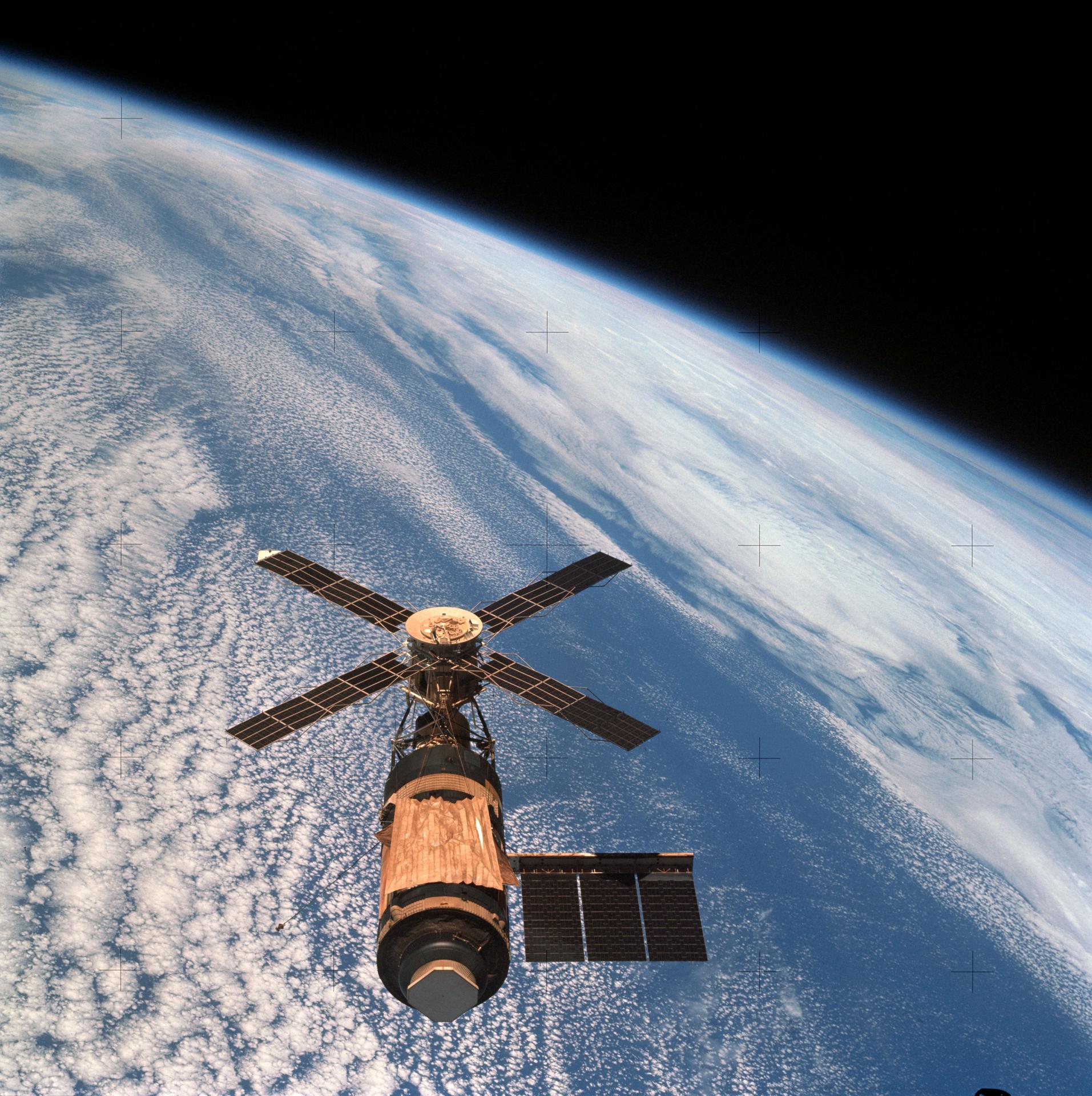
Skylab as the last crew says goodbye (NASA).
The United States took a different route. Skylab was essentially an enormous converted Saturn V upper stage. Launched in 1973, it gave its crews something previous spacecraft had lacked: room.
Three crews occupied Skylab, staying as long as 84 days. They conducted solar astronomy, Earth observations, medical studies, and experiments designed to determine what happens when human beings spend months rather than days in weightlessness. After all, why build a giant rotating station if people could simply learn to live without gravity?
Then again, we learned that long-term microgravity isn’t free. Bones, muscles, cardiovascular systems, eyes, and assorted other bits of the human body complain when they don’t have proper gravity. Still, a nonrotating station was far easier to build, so rotating wheels stayed on the drawing board.
Freedom Isn’t Free
By the 1980s, NASA was ready to try again. In his 1984 State of the Union address, President Ronald Reagan directed NASA to build a permanently occupied space station within a decade. What eventually became known as Space Station Freedom was supposed to be a large modular facility assembled by the Space Shuttle.
It would support research, Earth observation, satellite servicing, and eventually serve as a staging point for missions beyond Earth orbit.
Freedom went through redesign after redesign as costs and requirements fought each other. It did not rotate. While NASA redesigned Freedom, the Soviets quietly launched something considerably more important.
Peace In Orbit
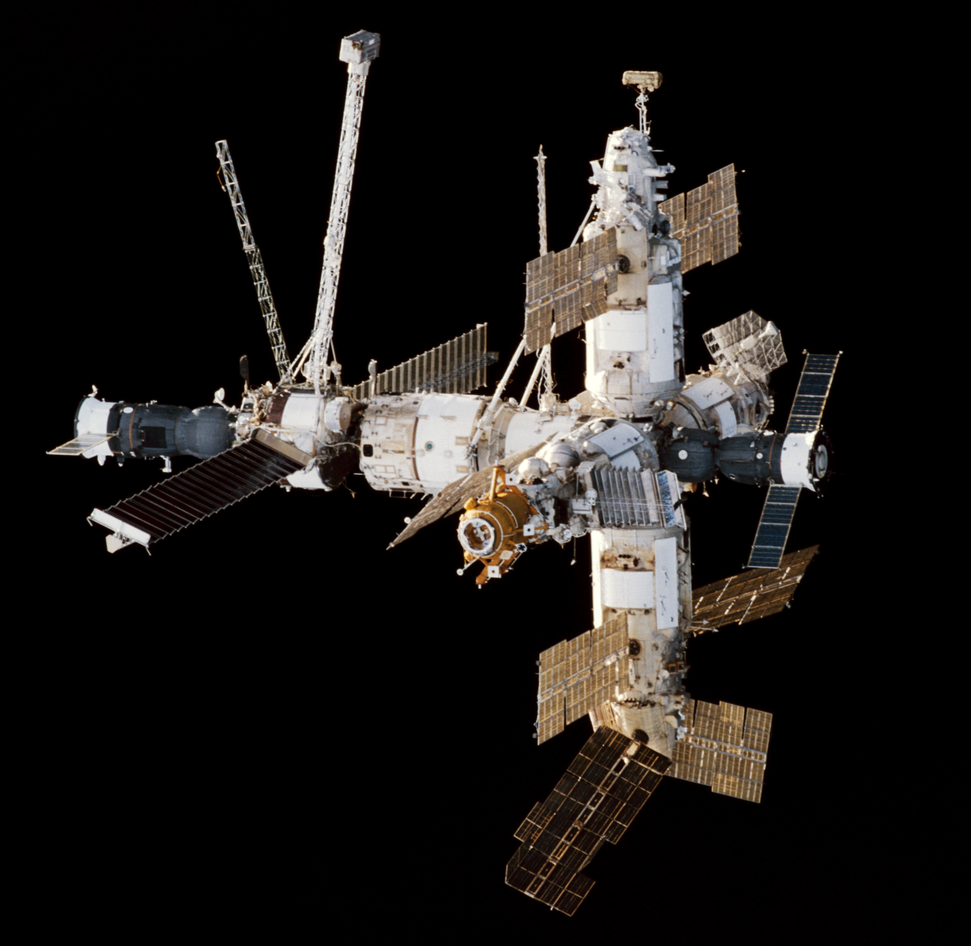
Mir seen from STS-89 (NASA).
On February 20, 1986, the Soviet Union launched the core module of Mir.
The name means “peace,” although the Russian word can also mean “world.” Unlike the earlier Salyuts, Mir was designed from the beginning as a modular station. Additional laboratory and equipment modules arrived over the years and docked around its core.
It looked nothing like Noordung’s wheel. It looked more like somebody had been assembling an enormous machine in a garage and kept finding useful places to bolt things on.
Mir represented decades of incremental Soviet experience: Soyuz, docking, Salyut, Progress, long-duration crews, orbital repairs, and modular construction. It demonstrated that a space station could become not merely a spacecraft but a place — one that crews could maintain, modify, repair, and inhabit for months at a time.
Where’s My Wheel?
That may be the most surprising thing about the history of space stations. The rotating station wasn’t some goofy 1950s science-fiction invention. Serious engineers were proposing artificial gravity before anyone had launched anything into orbit. Oberth discussed rotating stations in 1923. Noordung drew a remarkably complete wheel station in 1929. Von Braun made the concept famous in the 1950s. NASA seriously studied rotating stations in the 1960s. The physics works.
We’ve simply never needed artificial gravity badly enough to pay the cost.
If you can tolerate microgravity, a station can be a collection of pressure vessels, trusses, solar arrays, and docking ports. If you insist on one g at a comfortable rotation rate, suddenly you are contemplating a structure hundreds or perhaps thousands of meters across.
Still, Edward Everett Hale put people aboard an artificial moon in 1869. Noordung put them aboard a rotating wheel in 1929. Kubrick had airline passengers walking around one in 1968. So after more than a century and a half of talking about space stations, I have only one question: When do I finally get my rotating space station?
Using the special pens to remove the wax coating on the template. (Credit: Old Typerwriters and Calculators, YouTube)
Document duplication has been a highly desirable feature, long before medieval monks slaved over yet another illuminated manuscript by flickering candle light. Fortunately one part of the Industrial Revolution was the invention of machines like Cyclostyle copying machines, which covered a range of manual and automated devices. One such crank-powered device from 1890 is demonstrated in this video.
The Cyclostyle and neo-Cyclostyle copying system was quite simple yet elegant: by removing the wax coating on a special piece of paper ink from a screen-printing system could be pressed through the resulting template, and allow for repeat copies to be made.
With the machine demonstrated in the video the ink is applied to the top rollers, with the lower roller inking itself on them during the retraction cycle, before applying the fresh ink to the screen on the cycle following the insertion of a fresh piece of paper to print on. With this method many copies of the design on the waxed template could be made before it had to be replaced, which would have saved countless hours of work by artists.
After the machine in the video more advanced designs were developed, some of which we covered previously. These would automate more parts of the process, making it faster and more precise, before being replaced by newer technologies.
People have lived in space stations for decades now, but something is wrong with them. Where are the big rotating wheels? You know the ones. They show up in old paintings of the future and, perhaps most memorably, in 2001: A Space Odyssey. Spin a great wheel in space, and people can stroll around inside with something that feels suspiciously like gravity. It seems like an obvious idea.
It is also an old idea. Much older than actual spaceflight, in fact. But to find the beginning of the space station, we have to go back to a time when powered aircraft were still several decades in the future.
A Moon Made of Bricks
In 1869, Edward Everett Hale published The Brick Moon in The Atlantic Monthly. The moon in question wasn’t natural. Hale imagined building a 200-foot-diameter sphere made from bricks and putting it into orbit as a navigation aid. Sailors could sight it and use its known orbit to determine their longitude. There was only one small problem: the thing was accidentally launched with people aboard.
That makes The Brick Moon generally regarded as not only the first fictional artificial satellite, but also the first fictional space station. Hale followed it in 1870 with Life on the Brick Moon, describing how the accidental colonists got along up there.
Hale didn’t have rockets. He proposed flinging the thing into the sky with giant flywheels, but, then again, it was 1869, so we’re inclined to cut him some slack. As the 19th century turned into the 20th, however, people started doing the math.
Konstantin Tsiolkovsky is best remembered for putting rocket flight on a sound theoretical footing. The Russian schoolteacher wrote extensively about orbital flight and space habitation, envisioning people living in orbit long before anyone had demonstrated that a liquid-fueled rocket actually worked. His ideas included rotating habitats to provide artificial gravity.
Hermann Oberth’s 1923 book Die Rakete zu den Planetenräumen — The Rocket into Planetary Space — Oberth went beyond fiction and seriously considered a permanently inhabited station. He envisioned it being periodically supplied by smaller rockets, serving as an observation and communications platform, and even acting as a jumping-off point for trips farther into space. He also suggested spinning the station to give the crew artificial gravity.
Enter The Wheel
Noordung’s space station concept from his 1929 book.
But the space station that looks like the space station in your head probably comes from a different Hermann. Herman Potočnik was an Austro-Hungarian army officer and engineer who wrote under the name Hermann Noordung. In 1929, he published Das Problem der Befahrung des Weltraums, translated by NASA many years later as The Problem of Space Travel: The Rocket Motor.
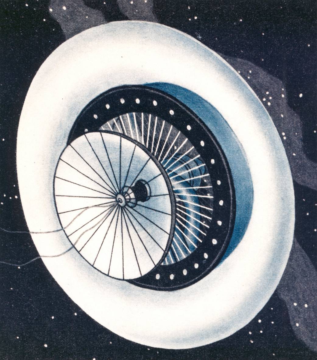
Noordung didn’t merely say, “We should have a space station.” He drew one. His station consisted of several components, but the memorable one was the Wohnrad — literally the habitation wheel. Living quarters occupied a rotating ring connected to a central hub. Rotation provided artificial gravity, while other portions of the complex could remain weightless. He considered power, communications, observing Earth, astronomy, docking, and the practical business of living in orbit. NASA calls his work one of the first detailed technical designs for a space station.
If you have seen Wernher von Braun’s famous wheel station from the 1950s, you may notice something. Von Braun certainly knew Noordung’s work — he had cited it years earlier — and the family resemblance between Noordung’s 1929 Wohnrad and the wheel station that von Braun and Willy Ley presented to American readers in Collier’s in 1952 is hard to miss. The only place we have found the articles is the reprints in Horizons, by the AIAA (start with page 46).
Whatever the exact family tree, von Braun was the man who put the wheel-shaped station into American popular culture. In 1952 he described a 250-foot-class rotating station in Collier’s, accompanied by some gorgeous Chesley Bonestell artwork. A few years later he took the idea to television with Walt Disney.
If you’ve never seen these, they are worth your time. Disney’s 1955 Man in Space and Man and the Moon let von Braun explain a remarkably detailed vision of rockets, orbital stations, and trips to the Moon to a mass television audience. A generation of kids grew up expecting this stuff. What happened?
Gravity, More Or Less
The attraction of the wheel is simple. You can’t really make gravity, at least not without bringing along a planet-sized lump of mass, but acceleration will do nicely. Stand on the inside of a rotating ring, and the floor keeps accelerating you toward the axis. In your rotating frame, it feels as though something is pushing you outward against the floor.
The acceleration is a=ω2r where (r) is the radius and (ω) is the angular velocity. Sadly, the numbers explain part of the problem.
If you want one Earth gravity at the floor, you need to either spin fast or have a large ring. For example, at 1 RPM the ring has to be 1.79 km in diameter. Speed up to 2 RPM, and you can get away with 447 meters. At 4 RPM, you are down to 112 meters.
Seems like you could just keep going faster, but there’s a problem. Four RPM doesn’t sound very fast until you are inside the thing moving your head around.
Humans can adapt to rotation, but increasing the speed makes Coriolis effects increasingly noticeable. Move your head, climb a ladder toward the hub, throw something, or even walk spinward instead of anti-spinward, and the results aren’t quite what your inner ear expects. NASA artificial-gravity studies have often used approximately four RPM as an important practical region for human tolerance, although this isn’t a hard physical limit and training matters.
There’s also a gravity gradient. Your feet are farther from the axis than your head, so they weigh slightly more. Make the radius large enough, and you won’t notice. Make the station small enough, and things get strange quickly. So bigger is better except when it comes to cost, of course.
Space Station V, still under construction. Note the window placement.
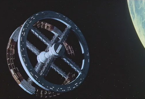
There is another oddity that movies sometimes get wrong. The outside circumference of the wheel is the floor. “Down” is away from the hub. Imagine a tire in space. You aren’t walking around on one of the flat sidewalls with the axle beside you. You are walking around the inside of the tread. So when a movie gives you a nice conventional room with a picture window on what looks like the outer wall, stop and think about where gravity ought to be pointing. Depending on the geometry, that window would probably be underfoot.
Stanley Kubrick got this wonderfully right in 2001: A Space Odyssey. Both Space Station V and the rotating centrifuge aboard Discovery make “down” follow the rotation. The famous jogging sequence works precisely because the circular wall of the set becomes the floor as the camera watches.
Next Time
Next time, I’ll look at early attempts to make a space station ranging from TASSEL, MTSS, and MARS to real Soviet and U.S. stations that had varying degrees of success. Spoiler alert: none of them are going to rotate for gravity.
Of course, people didn’t just imagine space stations. They also imagined moon bases, both fictional and actual.
Here’s a historical hack for you: you have a big, rolling pressurized kettle, also known as a steam locomotive. It needs water to make up for the steam constantly chuff-chuff-chuffing away, or bad things happen. How do you get water from an unpressurized tender into a high pressure boiler with no moving parts? What you need is a some way to inject steam with no moving parts — a steam injector, if you will. [Marc Flint] found that the steam injectors were the hardest part of a loco to understand, so he made a video for all of us once he’d figured it out.
The steam injector isn’t a new idea. [Henri Griffard] came up with it back in the 1850s to replace expensive and maintenance-hungry pumps. It’s rather ingenious and uses the fluid mechanics uncovered by another European bloke by the name of Bernoulli. First, the high-pressure steam from the boiler goes through a converging-diverging nozzle to drop its pressure and speed its flow up, just as you’d guess if you’ve seen Bernoulli’s laws. Even more vacuum-inducing is the presence of water: the steam, already cooled by its expansion, hits the water in the pipe open to the tender, and condenses into it, shrinking a couple of orders of magnitude, creating a vacuum that draws in no small quantity of feed water. That one we did not expect from Bernoulli, but it makes sense. So how to get from below atmospheric pressure to the 180-odd PSI or more in the boiler?
Well, the water is now moving at a good clip, between the Venturi effect and the momentum gained from absorbing that steam, so another converging nozzle is the trick. Bernoulli’s law, once more! A one-way valve lets the now-pressurized water into the boiler, with a gap in between to dump water while the pressure builds up. It’s a clever trick, and since the steam coming from the boiler makes it back inside along with at least some of its heat energy, it’s much more efficient in both coal and water than running a pump. It’s also a bit of a head scratcher how it works unless someone sits you down to explain it, so we’re glad [Marc] did.
Not many of us are likely to use this knowledge directly — unless we’re firing up a 90 year old boiler or building a new steam locomotive — but seeing how great engineers of years past made use of basic physical laws can serve both as education and inspiration.
Powered machinery started the industrial revolution, and it was automation that kicked it up another notch in the 20th century. The ability for machines to make things by themselves spurred increased output and in turn boosted economic growth. The concept became widely popular for manufacturers to implement, as any change with serious economic benefit tends to do. Fast forward to today, and advanced robots and fancy machine vision systems running on powerful computers are the norm in modern factories which create the many wonderful products that we all purchase, use, and enjoy.
Once upon a time, though, things weren’t so sophisticated. [Nicola Cimmino] came to Hackaday Europe 2026 to tell us all about a remarkably simple 1-bit CPU that used to run factories.
Logic, But Make It Cheap!
Nicola Cimmino used to frequent a facility that used to recycle electronic waste, which sold old bits and pieces of hardware by the kilo. Many times, Nicola would pick up odd boards with an eye to repurposing components for future projects. Eventually, one unremarkable looking chip caught his attention—the Motorola MC14500B. This chip was rather unique, being a rather simple processor with just 16 instructions and a 1-bit data bus.
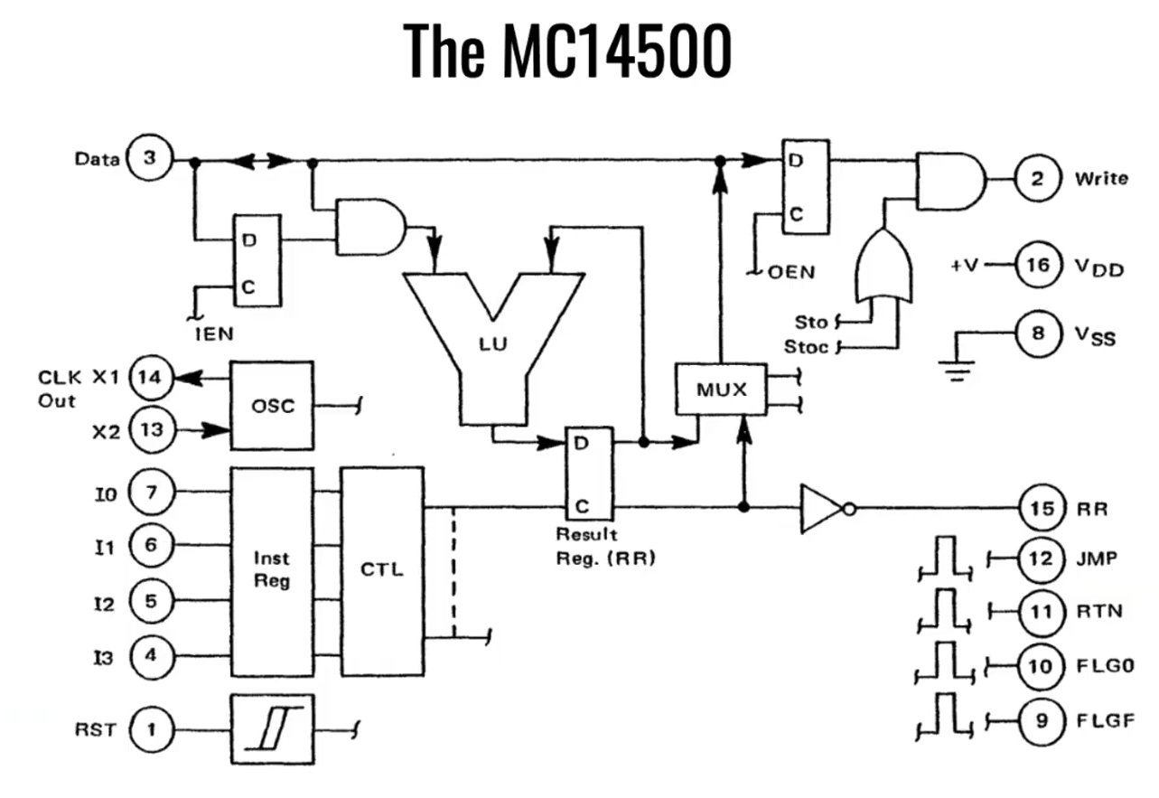
The simple architecture of Motorola’s basic 1-bit chip. Credit: talk slides
It’s worth examining the era in which this chip existed. Intel dropped the 4-bit 4004 in 1971, with the famous 8-bit 8080 landing in 1974. The Zilog Z80 came along in 1976, similarly an 8-bit design. And yet, when Motorola released the MC14500 in 1977, it landed with a rather slimline 1-bit design instead. Nicola notes that this likely came down to price, since populating a chip with more transistors cost more money quite significantly back in the 1970s. If the job could be done with less, it would make the part cheaper and thus more popular in the market. Bearing this out, Nicola explains that a 1976 Zilog Z80 used 8,500 transistors and cost around $200 USD, while an MC14500 used just 500 transistors and could be had in 1977 for the bargain price of just $5 USD.
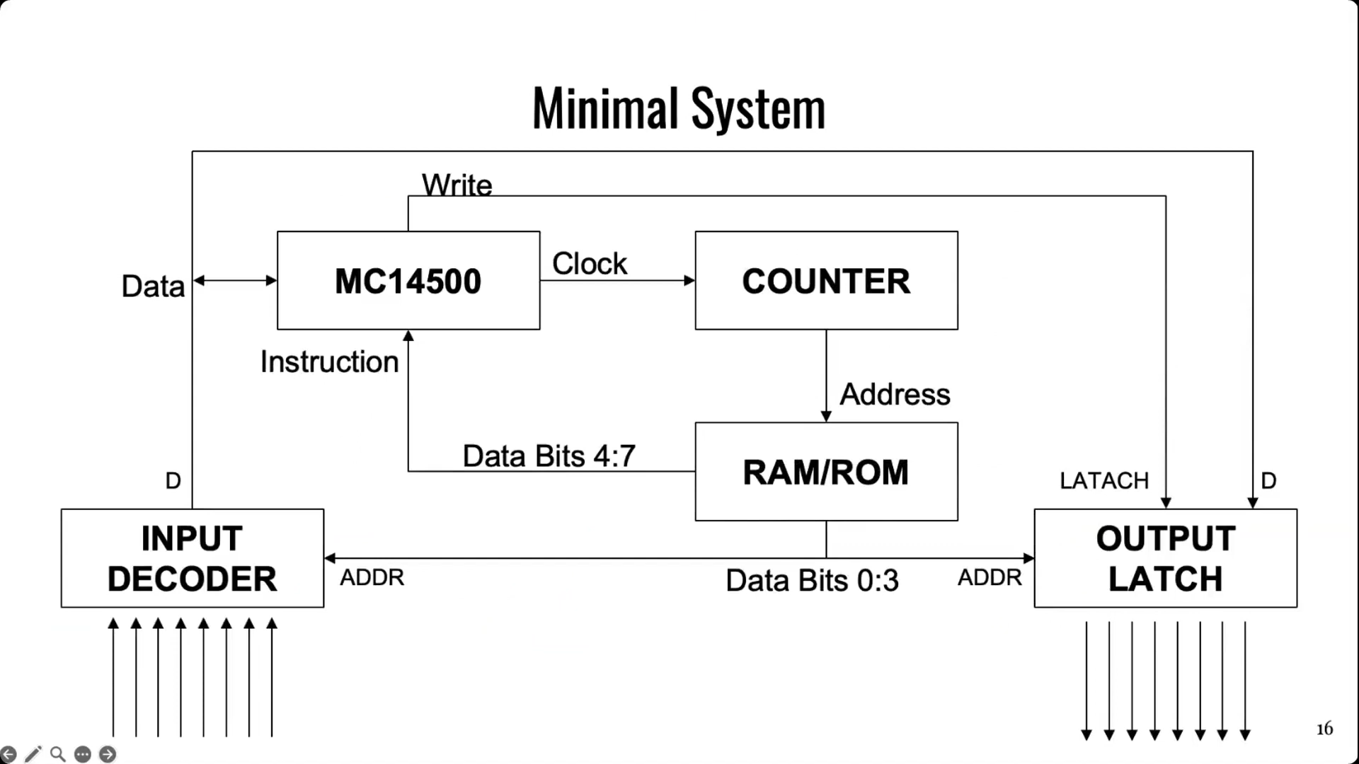
It doesn’t take much supporting hardware to get an MC14500 up and running. Notably, though, there is no memory or program counter on board, so those have to be added externally. Credit: talk slides
Back in the mid-1970s, automation in industry often consisted of simple logic that was handled by cabinets full of relays. This took plenty of bulk, required hard-wiring everything, and also involved plenty of electromechanical parts that could wear out. Changing logic required manually rewiring things which could be fussy and tedious at the best of times. In those days, the Programmable Logic Controller was just coming into use, developed to be a reprogrammable system for industrial automation tasks that was more flexible and reconfigurable just by reprogramming it.
The MC14500 sprung up as a useful tool at this time, powering a great many programable industrial systems. It was designed to offer the bare minimum requirements for its application, while leaving extraneous hardware for designers to implement if and when it was needed. The architecture is simple enough for Nicola to explain with a single slide. The chip came with a 1-bit logic unit, operating with a result register, a 1-bit accumulator and the data bus. A minimal system could be lashed up with the MC14500, a counter, some external RAM or ROM (since none was onboard), and an input decoder and output latch of 8 bits each. This setup would only allow for doing combinational logic, since there is nowhere to store the current state of the system. However, hooking some outputs back to the inputs could allow for sequential logic, since it would allow for storing the current state of the system via those outputs. Nicola then steps through various other configurational changes to addressing and system architecture that could be made to optimize the MC14500 for use in different ways.
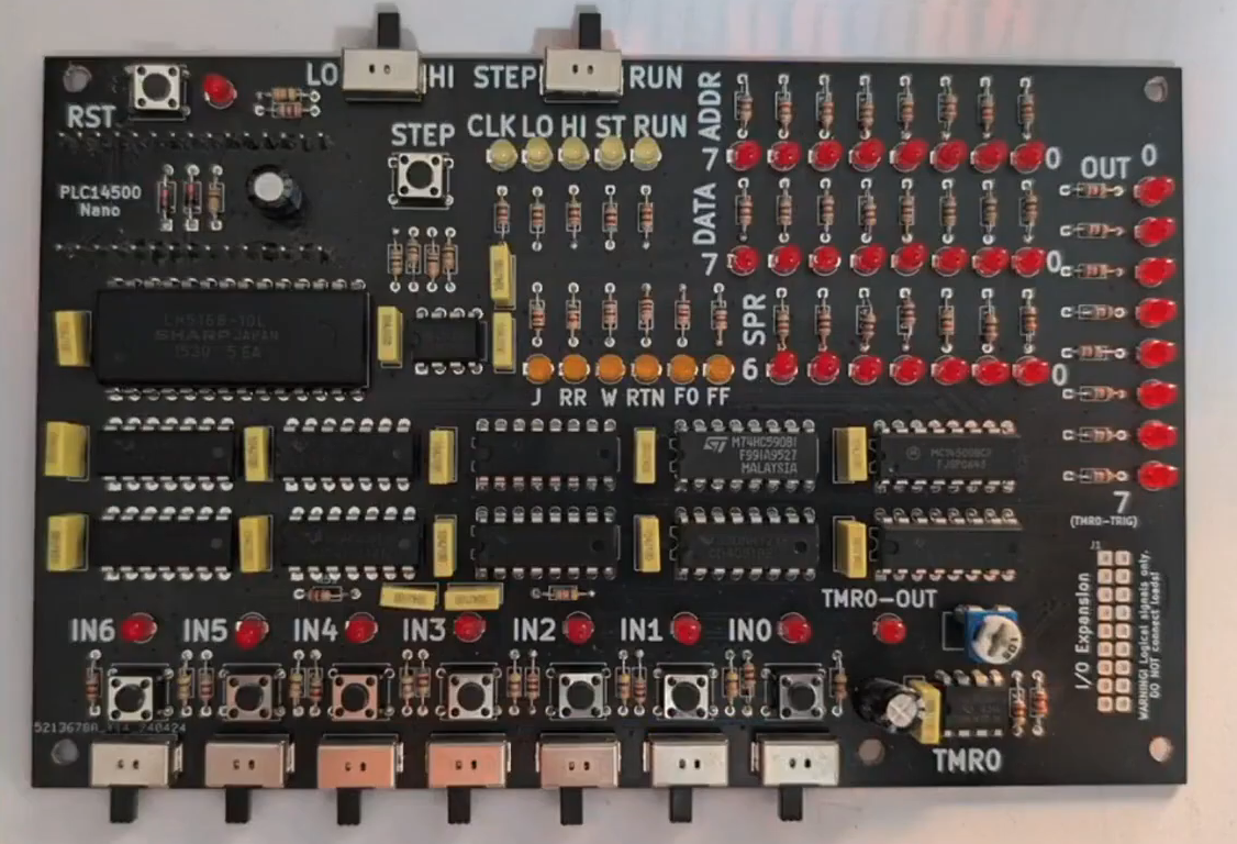
Nicola built a homebrew MC14500 system, allowing him to get to grips with the classic chip. Credit: talk slidesA more polished version came later, built on a custom PCB. Credit: talk slides
If you wanted to get to grips with using an MC14500 in industrial contexts, you would do well to pay attention to this talk, even if it came out some 40 years past the part’s heyday. Beyond the basic system architecture, Nicola explains how to use the limited instruction set, and how to get such a system executing simple programs in ladder logic, which remains somewhat of an industrial standard to this day. Beyond that, he steps up to more complex logic, like if/else conditionals and the use of some of the weirder instructions of the chip. He then shows off the hardware he built himself—both a breadboarded MC14500 setup built with wirewrap, and a more polished version on a custom PCB.
It’s not every day you get to learn about the nitty-gritty details of working with industrial hardware from the ground up. And yet, that’s exactly what Nicola brought to Hackaday Europe 2026. It’s an excellent primer on the topic, and also simply just good fun if you’re a fan of electronics and logic itself!

 Login
Login