โŒ

Normal view

There are new articles available, click to refresh the page.
Before yesterdayHackaday

Big Infinity Mirror Clock Invites You To Gaze Deeply

12 September 2026 at 16:00

[Andy Huot] has a fantastic-looking infinity mirror digital clock that really raises the bar. It uses high quality components, smart use of RGB LED animations, and a clever โ€œstacked diffuserโ€ vertical design to the 7-segment display elements that really enhances the infinity mirror effect. It needs to be seen in action, so check it out.

The end result is expressly portal-like, with the smooth animations of the LEDs really playing into the effect. The size helps, too. Itโ€™s 24 inches in diameter, giving it considerable presence.
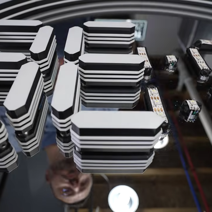
The stacked diffuser design for each display element really enhances the effect.

A basic infinity mirror design consists of lit elements sandwiched between a reflective back surface and a partially-reflective, partially-transmissive top cover. That same basic principle is used here, but with great care given to ensure nothing so much as a fingerprint spoils the illusion. For example, the top cover is a disk of acrylic with a 90% reflective film affixed to the inside surface. Thatโ€™s easy enough to DIY with some car tint, but [Andy] found that for the very best results it was worth having high-quality film professionally applied.

We like the use of 3D-printed custom jigs for soldering the segments of RGB LED strips, and holding the pre-measured wires in place with some putty is a great way to keep them in place while working. In case youโ€™re wondering, the mirrored acrylic making up the back wall has holes in it for mounting each segmentโ€™s LED strip in a holder, and running the wires to the rear.

The video (embedded below) documents every step of the assembly, and itโ€™s a serious build. While the design files for the 3D-printed parts are not free, thereโ€™s certainly enough detail for an enterprising hacker to replicate the design in their own way.

How To Fold Curved Lines in Metal Without Fancy Tools

11 September 2026 at 22:00

Folding a sheet of metal in a straight line is one thing, but how does one fold multiple curved lines into a sheet of aluminum without fancy machines? [John] demonstrates how to do exactly that with little more than hand tools and a fair bit of patience. The secret is drilling a lot of small holes along each fold line.

Complex shapes are possible with planning, hand tools, and patience.

First, a bit of background. [John] wanted to fabricate a curved piece of aluminum as cover that would match the sleek aerodynamic lines of a Belly Tank Lakester. The trick is that there isnโ€™t a single straight line to be found, and the fold lines are all curves. How can one do such folding with only hand tools?

[John] found that fabrication was possible by drilling small holes all along each fold line, then carefully bending as needed. The line of holes weakens the metal, acting like a score line, and allow the required curves to be made cleanly. Thereโ€™s some finishing work and straightening involved, but the hard part of making the actual folds is taken care of.

One method that didnโ€™t work was cutting a shallow groove in the metal to create something like a pre-scored fold line. [John] tried this and found that while the metal does indeed fold along the weakened line, the aluminum tends to crack in the process. When making a line of holes instead, the metal between each hole bends nicely.

This technique does mean the finished part ends up with small perforations along each fold, but the part is mounted on the bottom of the car and [John] says that heโ€™d have to look quite closely to notice. A little polishing goes a long way, too.

We have covered many ways to bend sheet metal and while machinery exists to do it exceedingly well, great results can be had with little more than simple tools and some patience.

Watch [John] go through the process in the video embedded below, or skip to 7:55 if you just want to see the end result.

Voicebox FX is a Blueprint for CircuitPython I2S Audio

5 September 2026 at 13:00

[Adafruit]โ€™s Voicebox FX gadget is a fun, well-documented project that serves another useful purpose: being a fantastic reference design for audio on CircuitPython, with I2S audio components. Be sure to check it out if you have a project that involves any of that and could use a few pointers, or if you just want to jog a few ideas loose.

I2S (Inter-IC Sound) is a protocol aimed squarely at moving audio data between components as digital signals. Our own [Jenny List] can tell you everything you need to know about I2S. Itโ€™s a relatively simple interface that is not at all fussy about actually being used for audio, and that has led to it being put to some unusual uses.

The Voicebox FX uses an I2S microphone, an I2S amplifier, and an RP2350 microcontroller to record and play sound as well as offer a variety of effects controlled by physical inputs. Itโ€™s all wrapped up in a slick 3D printed case, and while itโ€™s a fantastic reference design, it looks like a fun toy in its own right.

Straight Talk on 3D Printing Footwear At Home

25 August 2026 at 01:00

Printed footwear is an intriguing idea, but as far as projects go it is somewhat more complex than it first appears. This guide to 3D printing your own clogs not only provides a solid process, but also acts as a list of the challenges and pitfalls involved. After all, a piece of footwear is actually a fairly large object. Failed prints can be costly and time-consuming, so a guide like this is a valuable resource.

First of all, a 3D printer that can handle multi-material printing is called for. The footwear itself will be printed in TPU 90A as a sweet spot for hardness, but the print will require supports and those supports will need to peel away cleanly. The solution is a shoe printed in TPU with a rigid support structure of PLA. Using two different materials in the same print with anything remotely resembling efficiency calls for either a dual-nozzle print head, or a multi-toolhead printer.

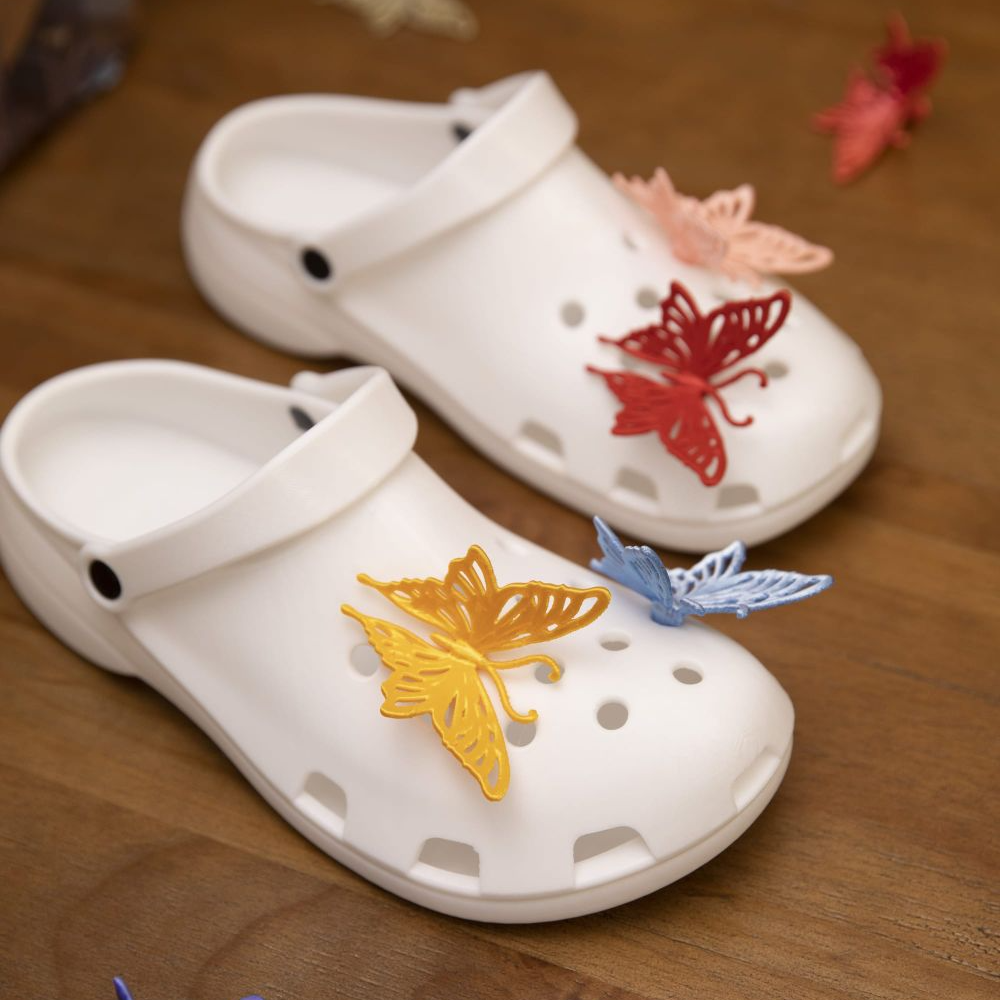
3D printing oneโ€™s own clogs can be rewarding, if not necessarily cost-effective.

Here we want to take a moment and say that while the guide itself suggests PETG is also a suitable support structure, we suspect this might only be true for the exact filament formulations used in the guide. The safer approach is to use PLA. Why? As weโ€™ve seen in other tests, PETG has been observed to stick extremely well to flex filaments in general, whereas PLA doesnโ€™t really want to stick to anything other than PLA. The exact formulations of TPU and PETG used in the guide might be compatible with one another, but in general we recommend sticking to PLA as a rigid support for flexible filament.

Assuming a capable printer and suitable materials are nailed down, one also needs to worry about keeping the TPU dry. It is very sensitive to moisture, which directly affects print quality. Youโ€™ll also need to dial in the settings โ€” a gyroid-patterned infill of 15% provides the right amount of โ€œsquishโ€, which is most effectively fine-tuned by changing the infill pattern rather than the density.

Is it worth the time and effort and filament cost to print oneโ€™s own pair of slip-ons versus simply buying a pair of Crocsยฎ? Maybe not, but it can still be rewarding and this guide will help minimize any failed prints in the process. And if you do get a nice print but the TPU is sticking a little too well to the build plate, reach for the isopropyl alcohol.

โŒ
โŒ