One of the things we used to appreciate about broadcast television is that… you kinda just got what you got. You didn’t have to choose beyond picking a channel, and then you settled in to imbibe whatever media the CRT was spraying at you. A vague recreation of part of this experience is now available, in the form of [Sergei’s] RND.TV.
The concept is simple enough—it’s a webpage that plays random videos from The Internet Archive. Each session draws videos from a random sequence, with no algorithm or fancy social media nonsense to push some videos over others. As you might expect, you’re in for lots of random and weird stuff, from old Army videos to middle-school basketball games. You can swipe to flick to a different “channel” if you don’t like what’s playing, or you can mark videos you like if you fancied what came up in the random feed. You can also use your phone as a remote if you want to sit back and flick channels like it’s the 90s again or something.
We’ve featured other projects in a similar vein before—like little TVs from The Simpsons that play episodes on repeat. Sometimes, it’s fun to just avoid the paralysis of choice, and a random stream of content can provide that relief. Or, alternatively, you could always hook up your TV to an antenna and watch free-to-air… it’s still out there, for those that wish to view it!
Once upon a time, you had to carefully budget your microcontroller’s resources if you wanted to do something as simple as flash a bunch of LEDs. These days, they’re powerful enough to humiliate the game consoles of yesteryear. [alexkid77] demonstrates this well, having the ESP32-P4 run Tomb Raider.
Now, [alexkid77] hasn’t gone so far as to create a PlayStation emulator on the ESP32 or anything quite like that. Instead, this is a port—and not of the original Tomb Raider release, either. [alexkid77] started with OpenLara—the classic game running in an open-source engine. With the ESP32-P4 having two cores running at 400 MHz each, there was plenty of processing power on tap to run the engine with a software renderer at 320×240, which is hardware scaled up to 1024×600 via the Pixel Processing Accelerator (PPA) built into the chip. There’s also stereo audio with an ES8311 codec hooked up, while input is via a USB HID keyboard.
It’s funny to think that it could actually be cheaper and quicker to get Tomb Raider running on an ESP32 and a cheap LCD display versus actually going out to buy a PlayStation and an original game disc. But that’s the way the cookie crumbles in 2026. At least you don’t have to play it on an S3 Verge.
Remember those tiny little droids skittering around the pristine corridors of the Death Star in Star Wars? [heychaostheory] has put together something vaguely along the lines of those charming little mobile toasters. It’s an autonomous mouse droid with party mode!
The build is interesting in that it’s based on an off-the-shelf metal robot chassis—which provides mounting points for the gearmotors and wheels that make up the drivetrain. The mouse droid body sits atop this, being a 3D printed part that is afixed with heat set inserts and nylon standoffs. It’s 3D printed and expertly decorated with a fun vibe. Inside the body lives an Arduino Uno, hooked up to an L298 motor driver board and ultrasound sensors used for obstacle avoidance. It’s also got a smattering of LEDs to flash, because blinkenlights matter. The best bit, though, is the party mode button, which fires off music via a DFPlayer Mini module.
The mouse droid may not be as flashy and imposing as the Droideka or as mechanically impressive as BB-8, but that just makes it more accessible and fun to build. You can easily create one at full scale without breaking the bank. If you’re cooking up your own fun droids in the workshop, don’t hesitate to let us know. Video after the break.
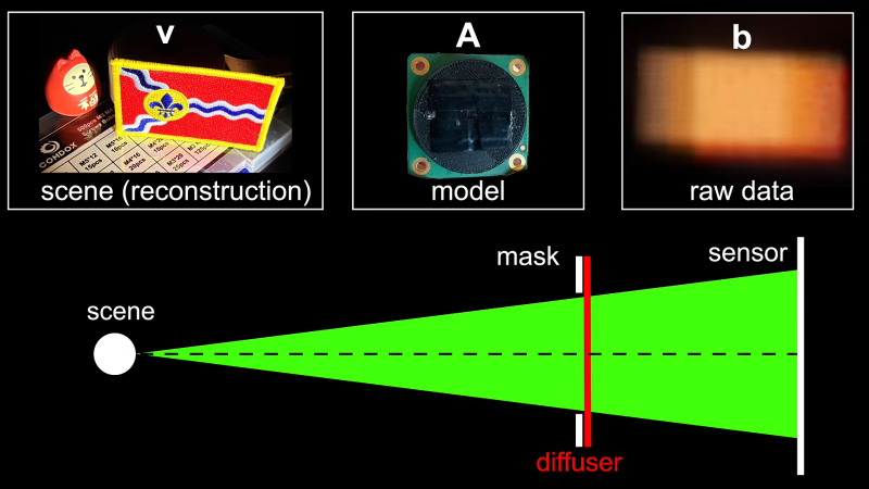
There are plenty of ways to capture 3D images or simulations of such if you know what you’re doing with camera hardware and fancy mathematics. However, a little more unusual is the idea of capturing a 3D image while using no lens at all — and yet, [okooptics] has achieved just that!
The basic concept builds on an older project from [okooptics], wherein images were captured from a Raspberry Pi camera with no regular lens element installed. In its place was a thin layer of Scotch tape over the sensor, acting as a diffuser. With the right deconvolution math, it’s possible to actually recover a real image out of the blurry mess this setup initially captures. [okooptics] was then able to push this into three dimensions by weighting the point spread function used to deconvolute the image.
Adding directional bias to the process creates a similar effect to slightly shifting the cameras position, actually revealing a view from a slightly different angle of objects in front of the camera. [okooptics] does a great job of explaining the science behind how this is possible and the practical limitations of the technique, also referencing research papers that have explored these ideas in great depth.
It’s math heavy to extract 3D data from what otherwise looks like blurry nothingness, but it’s possible if you know what you’re doing. For a fuller understanding, it’s worth diving into [okooptics] earlier work in this realm, taking photos with Scotch tape in place of a lens.
Drones have become a potent military threat, particularly on the small scale. Nimble multi-rotor drones are fast, difficult to spot, and can cause plenty of harm if allowed to go about their work unhindered. The first step to dealing with this issue is detection—a problem that [Agam Rossen] has put some work into.
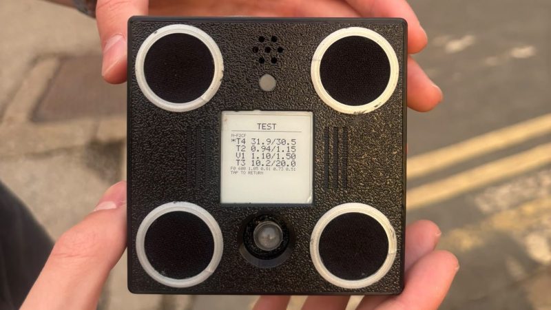
The result is VolAnti—an open-source drone detector. This route was chosen as a reliable way to detect incoming multi-rotors, since spinning propellers tend to create a telltale sound that can be plucked from the noise quite specifically. In a world where fiber optic drones eschew RF emissions, it also proves particularly useful for early warning of such craft.
VolAnti relies on a small four-microphone array, with the I2S output of all four mics summed together. The output is then fed into a 2048-point FFT running every 32 ms on an ESP32-S3. A comb score is given to try and pick out different blade rates from 70 Hz to 2000 Hz. Multiple detection algorithms run in parallel, because [Agam] noted a problem—using an adaptive noise floor would miss drones that arrived in the area and hovered in place. With the noise not varying, it would get filtered out by the adaptive floor, so one algorithm in the four runs with no floor to catch drones that aren’t moving. Files are on GitHub for those curious to learn more.
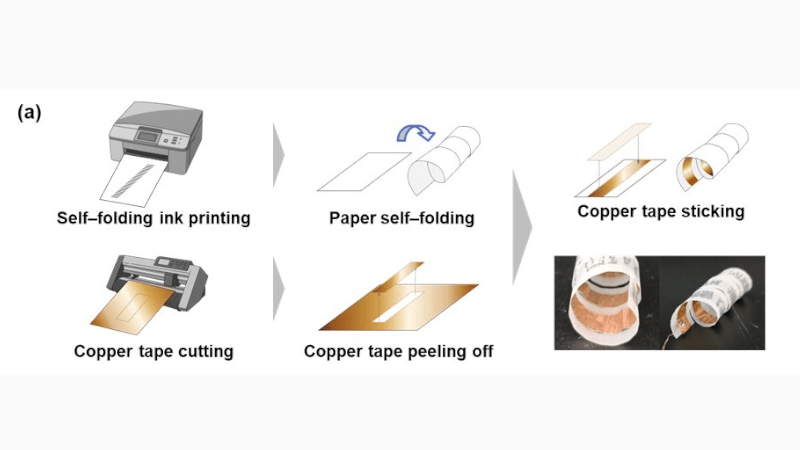
The project involved creating paper-based sensors that could be worn on the body. These sensors were designed to be self-folding into helical forms, which would allow them to adapt neatly to the wearer over a wide range of body dimensions. This was achieved by using a standard inkjet printer to print patterns onto a flat piece of paper, with the printed patterns creating a self-folding behavior in the paper itself. Copper tape was then applied to the paper in order to act as an electrode for picking up triboelectric signals and measuring galvanic skin response. The idea is that these methods could be used to quickly and easily produce custom low-cost wearable sensors for a range of applications.
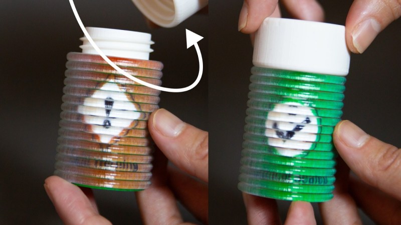
You can 3D print all kinds of things, from Yoda heads to little models of Pikachu. Eventually, though, most of us get to a point where we want to print something a little more interesting. The lenticular prints developed by MIT CSAIL are very much that. (h/t Core77).
The ShiftLens concept is simple enough—there’s a lens layer printed in transparent material. Beneath that, lives a patterned layer in alternating colors, corresponding with the linear lenses of the layer above. Then, there’s an actuation mechanism that can shift the lens layer relative to the pattern layer. This creates a changing color effect as the mechanism is shifted. The actuation mechanism can be a knob, switch, or roller—anything that moves the layers relative to each other. On its own, it’s a bit of a curio—but there are some fun demos. In particular, using the lenticular printing on a bottle to form an indicator for when the container is closed properly. There isn’t a publicly available design tool for these prints yet, though the team developed one for Rhino that they used internally for the project.
It’s a pretty interesting application of 3D printing, and one that we fully expect a bunch of YouTubers to replicate within the month. We’ve featured some other great print hacks lately, too, like a slicer that lets you print horizontal overhangs without support. Video after the break.
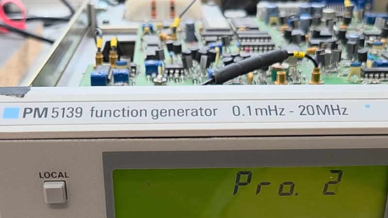
The Philips PM5139 is not famous. It won no great victories on the battlefield, nor was instrumental in changing the political landscape. It was just a useful function generator that you might find on a workbench somewhere, doing its job quietly and relatively accurately. [doctormord] has been doing the work to reverse engineer this humble piece of hardware.
The PM5139 is poorly documented; the only existing service manual out there is for the PM5138A, a less-capable sister model. Hence, there was some value in reverse engineering the device to understand it better. Work started with two EPROM dumps capturing what Philips put in the box all the way back in the early 1990s. From there, the code was examined and tinkered with until [doctormord] felt confident to modify it and improve upon what was already there. This was achieved with the aid of an 8051 emulator that could run the code to make it obvious what was going on. The result was a custom “V2.0” firmware that adds six arbitrary waveforms to the function generator and the ability to play simple music, amongst other tweaks.
Oftentimes, when we’re using a microcontroller, we’re whipping up some very specific code focused on executing a particular task. The device is set up to execute code that does exactly what we want with minimal overhead. However, sometimes, there are scenarios where it pays to go with a somewhat heavier setup, wherein the microcontroller runs an operating system for the benefits that offers.
Federico Terraneo came to Hackaday Europe to discuss this very topic. He talks about kernel architecture, real-time operating systems, and how to best use C++ in the world of microcontrollers.
Microcontrolling
The talk begins in a helpful place. Federico starts by explaining what an operating system actually is. Basically, it’s the software that exists between the hardware and the applications that run upon it. Breaking it down into parts, an operating system typically consists of a main kernel, atop which sits things like the basic system services, libraries, and device drivers, along with utility programs necessary to maintain and work with the system. The user interface sits on top of all that, which allows the user to select and run applications and generally use the operating system to get things done.
Federico talks about the Miosix RTOS as a practical implementation of the fluid kernel architecture.
Of course, different operating systems differ in the specifics of their architectures. Monolithic kernels, such as Linux relies on, keep a split between kernelspace and userspace. This is where where the kernel has full hardware access running on the CPU in system mode, while the applications run in user mode without such direct access. Monolithic kernels typically only run on architectures with memory management units (MMU)—think full-scale computers with proper CPUs, like your laptop or desktop. Unikernel operating systems, like FreeRTOS, are a little different, where applications and the operating system are collapsed down into a single executable binary that runs with raw hardware access. There is no abstraction, no memory protection, or anything like that, which makes the architecture easier to run on typical microcontrollers. There are also microkernels, which aim to minimize the amount of code that runs in system mode, pushing things like drivers and filesystem access into userspace. This architecture still needs an MMU, and is mostly only seen in niche uses where high security and/or attention to safety is critical.
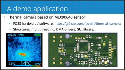
A thermal camera running on a fluid kernel system serves as a great demo application for the platform, showcasing several important features like multithreading and DMA.
When it comes to microcontrollers, unikernels are the most relevant architecture to think about. However, they have limitations–in stability, in security, in the fact that there is no run-time code loading or any way to easily partially upgrade the system. The fluid kernel, which Federico came to explain, aims to solve some of these issues. It hopes to offer a scalable operating system solution that works across the world of embedded computing, where sometimes microcontroller resources are limited and where memory management units seldom exist. It’s also intended to be compatible with standard APIs—think POSIX, C++ standard libraries, and all that. Federico calls it the “UNIX on a chip” concept.
The fluid kernel aims to exist at the intersection of the monolithic kernel and the unikernel. It allows hosting applications in kernelspace or in userspace as needed. A fluid kernel is also built to be POSIX compliant twice—with the same API whether you’re operating in kernelspace or userspace. The fluid kernel concept is designed around achieving process abstraction via the hardware Memory Protection Unit (MPU) common in modern 32-bit microcontrollers. It’s not quite an MMU, and can’t do all the same fancy virtual memory tricks, but it’s enough to provide a basic level of memory protection on a microcontroller platform. The fluid kernel can also become a unikernel if so desired as a compile-time option, which takes away process support while reducing code size significantly. It allows for unikernel devleopment that can be upgraded into a fluid kernel later by flipping the compile-time option the other way.
Federico does a great job of explaining the pros and cons of the fluid kernel architecture, and explores the security implications inherent in going this route. The Miosix RTOS is discussed as the practical implementation of this philosophy, and there’s even a helpful diversion into the efficient use of C++ on microcontrollers. If you’re getting serious about embedded development, or you just want to learn about a new architecture you might find useful one day, it’s a great talk to dive into on your next lunch break.
The concept behind the project is simple enough—grab the digital signals that feed the MC6847 IC responsible for generating the analog video output, and use them to create an all-digital video output over HDMI. [Scott] achieved this by using a Tang Nano board, which hosts a Gowin GW1N-1 FPGA. It’s able to snoop the signals heading to the MC6847 and, with some supporting components and level shifters, it can spit out video befitting modern screens. To make the system nicely complete, an analog-to-digital converter is also included to pick up the analog sound output from the TRS-80 and spit it out down the same HDMI cable. Such convenience!
There’s something strangely anachronistic about grabbing a TRS-80 off the shelf and hooking it up to a flatscreen with a single HDMI cable. Regardless, it’s a pretty great way to play with your old machine without having to futz with heavy old CRTs. We’ve featured plenty of similar projects before, too.
Disk Defragmenter was a wonderful utility that Microsoft included with Windows back in the day. Back then, you’d use it to theoretically speed up disk access. Today, you can run a fun simulation right in your browser thanks to [Dennis Morello].
The theory behind defragmenting hard disks was simple. Your hard drive would store data on spinning magnetic platters. Sometimes, a given file or group of files would end up with their different parts scattered across different parts of a platter, or even multiple platters, as the file system tried to slot everything into the space available over time. On a drive accessed with a literal physical mechanism, this fragmentation of files across multiple areas of a disk could cause functional read speeds to drop. To solve this, you could defragment the drive, wherein a utility would grab disparate bits of different files and put them physically closer together on the drive platters, such that the read heads could access larger contiguous chunks of files more easily.
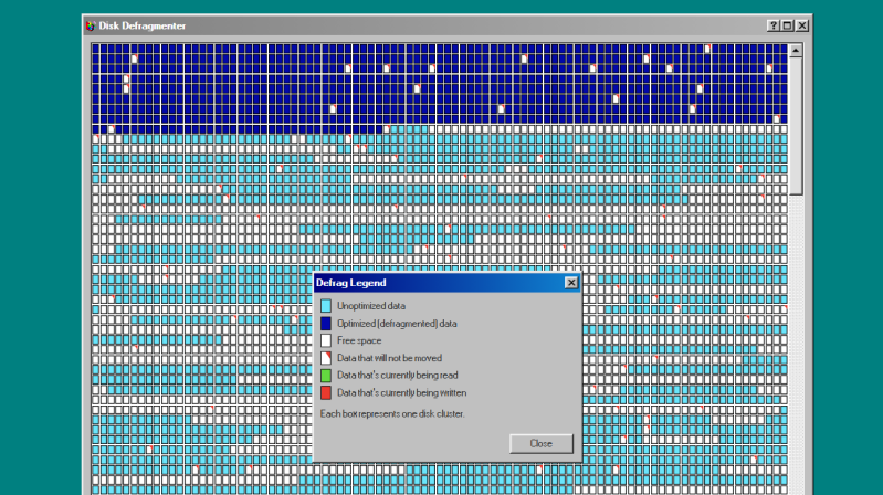
[Dennis’s] project does none of that. It just simulates the visuals and sound of running Microsoft’s disk defragmenter tool from Windows 98. It’s got the little rows of squares that get rearranged, blue for unoptimized data, dark blue for defragmented data, and white boxes for free space. It’s got the progress bar along the bottom, too, and a nice little simulated sound of a hard disk ca-chunking away as it shuffles little bits of data to and fro. This was the kind of thing you’d do on a rainy Saturday afternoon in the 1990s, just watching your PC make itself a few percent faster while you drank coffee and wondered if your ex-wife Jacinta was ever coming back. She never did, but you did notice that Age of Empires II loaded a fair bit quicker after you ran a full defrag on your main drive. Sometimes, that’s as good as it gets.
Modern file systems are better at managing issues like fragmentation, and the virtually instant seek speeds of solid-state drives essentially eliminated the need for defragmentation for good. Still, it’s fun to visit an ancient tool from yesteryear and remember what it meant to us way back when. Maybe you could give Jacinta a call, too, just for old times sake, and discuss that time a Janet Jackson song started crashing brand-new Windows laptops right out of the box…
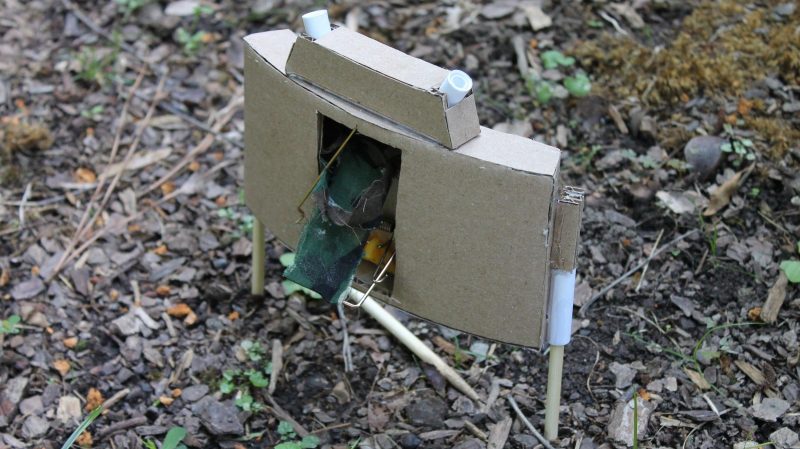
The Claymore mine is a rather fearsome weapon of war, using explosives to blast a cone of shrapnel towards advancing enemies. It’s not really something you should try and build at home. An airsoft version, though, is altogether more appropriate. [RegiBlackwood] has developed a simple way to build exactly that.
It’s a cheap and cheerful build, with the claymore housing itself built out of cardboard. Wooden dowels are used to stake it into the ground, just like the real thing. In the center of the housing sits a regular old mouse trap. Only, it’s been modified to hold a sling carrying a payload of BBs. The trap is also tweaked to make its spring more powerful, and to enable it to be triggered with the tug of a tripwire. When triggered, the mousetrap fires and hurls the sling forth, spewing a rain of BBs from the front of the device—ideally quelling the advance on your position.
Built properly, it’s a fun piece of airsoft hardware that could really change the dynamics of your regular game. If you’re looking to do point defence, you might also consider building yourself some automated turrets as well…
There are many ways to detect stress in an individual. You can use self-reporting checklists, you could try and measure various vital signs like respiratory rate and pulse and infer things, or you could observe the levels of hormones like cortisol in the blood.
Or… you could pull some parts out of a Playstation 4, and get hacking. Edwin Hwu did precisely that, creating a device that can image the skin down to the nanometer and potentially even determine fine details about an individual’s health status. He came to Hackaday Europe 2026 to tell us all about it.
Look Closely
Edwin’s background is very relevant to this project. He worked in a research institute in Taiwan where he collaborated with the German National Metrology Institute, working on atomic resolution imaging on silicon wafers. When you’re doing sub-nanometer calibration work for the semiconductor industry, that’s serious stuff, as is the X-ray microscopy that Edwin has dived into. When it comes to looking at things at very tiny scales, he knows his stuff. He’s also done plenty of work on real-time cell culture monitoring, skin assessments, and even high resolution 3D printing. It’s a broad skill base that all fed into the project he came to Hackaday Europe to talk about.
A single strand of DNA imaged with a DVD-based AFM setup. Credit: talk slides
There is a problem with optical microscopy that comes down to the diffraction limit of light—which means you can only image down to a resolution of around 1 micrometer. That’s why we use scanning electron microscopes for so many finer tasks, because the diffraction limit of electron beams is so much smaller. This allows the imaging of structures like carbon nanotubes or buckyballs, but with the limitation that the surface must be conductive and the imaging be done in a vacuum environment. A newer technology is the atomic force microscope (AFM), which involves using a very sharp probe with a tip of just 2-3 nanometers to actually touch molecules. This can be done without a need for a conductive surface or vacuum. When taking this approach to look at things on the nanometer scale, Edwin likens it to trying to poke a 1 euro coin with the tallest mountain on Earth. It’s a precise device with incredibly high resolution, but the average AFM costs half a million euros, and is incredibly bulky and slow at what it does. That is, unless… you find a way to build one on the cheap.
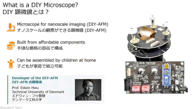
Atomic force microscopes were once incredibly expensive and cumbersome pieces of laboratory equipment. Now, it’s possible to build one yourself from an affordable kit, and it’s easy enough for children to put together. Credit: talk slides
Some time ago, Edwin created an atomic force microscope using the optical head of a DVD player, achieving a resolution of 0.39 nanometers. With this build, it was possible to image a single strand of DNA. Edwin also talks about how he used simple piezoelectric buzzers to create an ultrafine scanner for this work. The piezo elements are used for actuation, since they can be controlled to make incredibly minute movements. The work developed to the point where DIY AFM kits were made available at a mere fraction of the cost of traditional laboratory-grade installations.
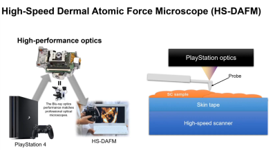
The Playstation 4 proved to be the perfect donor for a high-quality AFM build thanks to the performance of the Blu-Ray optical head. Credit: talk slides
This work spawned a greater plan. Through his talk, Edwin explains how he figured out that e-waste gaming consoles could be turned into cutting-edge atomic force microscopes. Specifically, the Playstation 4 was the perfect candidate, with its high-end Blu-Ray optical head which is capable of reaching the diffraction limit of light. The Blu-Ray optical head is used to monitor the movement of the AFM probe, while scanning it is achieved with a piezo rig just like the earlier DVD-based build. It also has the benefit that the Blu-Ray hardware is built for higher data rates, meaning it’s possible to stream data from the optical head much faster for a quicker AFM scan. Edwin refers to his build as the HS-DAFM—for High Speed Dermal Atomic Force Microscope—since it’s 100 times faster than traditional laboratory atomic force microscopes.
By looking at the skin at a nanoscale level, the tool is useful for investigating conditions like atopic dermatitis, among others. Credit: talk slides
The word “dermal” is important—because Edwin has put the build to use in examining skin nanotexture, for diagnostic purposes. His talk explains how, combined with machine learning systems, the tool can be used to investigate skin conditions and help in the diagnostic process. It’s also become useful from the perspective of cosmetics, and looking at how the skin looks at the nanoscale due to factors like aging and UV exposure. With the aid of machine learning tools, Edwin has found that it’s even possible to determine if someone has asthma with 75% accuracy, just from a skin scan. There is even an exploration of mental stress versus skin nanotexture, albeit in a very preliminary stage.
If you’ve ever wondered about the finer details of doing atomic force microscopy on the cheap, or how skin texture holds the secrets of so many health-related matters, Edwin’s talk is a great one. Sometimes thinking outside of the box and the limitations of commercial laboratory equipment can lead to wonderous things, as it did here!
If you’ve heard the high-pitched whine or buzz from an electronic device when a current-carrying inductor is vibrating, you’ll know how unpleasant it can be. It’s common in all kinds of equipment, but it’s become a particular annoyance of late in hardware like PC power supplies, GPUs, and cooling pumps. There is plenty of hearsay on the web about which parts whine and which don’t, and [Lowell Wood] wants to get to the bottom of it.
To track the issue, [Lowell] has put together the Coil Whine Database. It accepts user reports on hardware, regarding the level at which coil whine is present. A score of 0 is given to a part that is inaudible in a quiet room, with higher scores representing higher sound levels. A part scored at 2 is audible working at a desk with the computer under load; a part scored at 4 is audible even when the machine or device is at idle.
For now, the database is largely empty—[Lowell] has just opened submissions, adding a report on their own ROG Astral RTX 5080 card for good measure. If you want to submit a report on a unit, either silent or noisy, that’s simple enough—just fill in the coil whine report form. Over time, submissions will hopefully grow, and it will be easier to get a good idea of what equipment whines and what is likely to operate silently out of the box.
The database aims to present a guide to what parts whine, and how much, noting that any given population of devices tends to vary. To that end, any given device won’t be reported on publicly until it receives at least 5 reports. To counter bias, reports of silent parts will be weighted higher, since it’s unlikely that people happy with their quiet hardware will be rushing to research this issue or report it to a database. Relevant files to the project are available on GitHub for the curious.
The hope is always that a good business card will leave a good impression. For those in the electronics field, they also serve as an opportunity to showcase creative design skills. [Wilson Harper] demonstrates that ably with a rather nifty energy-harvesting build.
The card is based around a thin PCB in the typical business card size. It’s populated by 21 Charlieplexed LEDs, a small microcontroller, and some supporting components. Now, this is normally where you might expect the device to be powered by a small coin cell, maybe deftly integrated into the PCB thickness itself to make the card less cumbersome. But no—[Wilson] went a different route. The thing is that in 2026, most of us are carrying phones with NFC readers built in. Thus, the card was built to harvest this source of energy with a PCB trace antenna, designed with the aid of STM’s antenna inductance tools and an LLM script lobbed into KiCad. All one needs to do is to pop the card on the back of a phone and the LEDs animate joyfully.
When it comes to building real-world flying vehicles, testing can be arduous and expensive. You have to find somewhere to fly, then you have to contend with environmental conditions and the possibility of damaging your craft if things go wrong. Simulation is a great solution to this, allowing testing without so much risk. To that end, [AlexanderRex] whipped up a platform for testing UAVs from the comfort of your computer desk.
PteroSim is intended as a comprehensive test bench for simulating autonomous aerial vehicles. It can run PX4, ArduPilot, and Betaflight binaries right in the simulator. The autopilot code is given simulated sensor data, and in turn responds with actuator commands, just as it would in a real craft. The simulator runs the flight dynamics using JSBSim, and the resulting scene is rendered in Unreal Engine 5.
If you’ve ever wanted to quickly road test different autopilot settings without heading out to the field or risking hardware, this is a great way to do so. It’s hard to beat the speed of iteration that is possible when testing on the computer on your desk. We’ve featured similar work before, too.
The average hot water is a relatively simple appliance to understand. It uses gas or electricity to dump energy into water in the form of heat, keeping it at a pleasant temperature for uses like bathing and cleaning. Basic mechanisms are in place to ensure the water stays at a relatively constant temperature, neither too hot where it could cause burns, nor too cold such that it wouldn’t be fit for purpose.
Legionella pneumophila is a bacteria that loves to grow in warm water. It can enter the body via aerosol and cause of Legionella’s disease. Credit: CDC, public domain
One of the interesting problems of our modern era is that changing our water usage has changed the risk profile for pathogens growing in hot water. NIST has noted for some time that while the pipes in our walls haven’t changed size, things like our shower heads have changed their flow rate to save water. Less flow rate in the same sized pipes means that water stays in the pipes for longer, increasing the time in which harmful pathogens have to grow in that environment.
Chief amongst these pathogens? The one most commonly feared is legionella pneumophila, the bacterium responsible for causing Legionnaires’ disease. The severe form of pneumonia comes with a fatality rate of 10%, and infection typically comes from inhaling aerosolized droplets containing the bacteria.
Of course, a great way to create aerosolized droplets filled with bacteria is to spray not-quite-hot water through a shower head. This is why hot water systems, particularly in large multi-occupancy buildings, are a risk for such infections. Legionnaires’ disease is rare, but it’s always out there, with 6000 confirmed cases showing up in the US each year. It’s possible that the true number is up to 10 times higher because the disease isn’t routinely tested for. The disease’s rarity is in part because engineers and tradespeople put in plenty of work to minimize the ability for the bacterium to breed in hot water systems. As NIST’s work demonstrates, though, there is possibly even more that could be done to tackle this problem.
Ideally, your hot water pipes in your house would not host any nasty bacteria. But often, hot water systems sit around 49 °C (120 °F), a temperature that’s hot enough to be useful and pleasant without a major scalding risk. Legionella pneumophila won’t easily grow at that temperature; the bacteria thrives between 20 °C to 45 °C (68 °F – 113 °F). Unfortunately, though, it’s not hot enough to kill the bacteria completely. Furthermore, water cools as it travels through pipes to an outlet, and thus pipes can be a perfect environment to spur further growth.
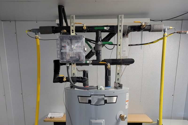
The solution developed by NIST is simple—jack up the set point of the hot water heater, then fit a heat exchanger on top to cool outgoing hot water with the incoming cold supply. Credit: Brandon Hayes/NIST
The simple solution would be to simply jack up the hot water system to store water at a much higher temperature, say around 70 °C (160 °F). This could be undesirable in many contexts, though, as water that hot can more easily cause burns. It would be ideal to store the water at a higher temperature, while making sure it was delivered at a slightly lower temperature so it didn’t hurt anybody when it left the tap or shower head.
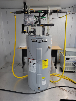
A prototype unit whipped up by NIST cost only about $100. Credit: NIST
It turns out that there is a remarkably simple way to achieve this. NIST developed a simple heat exchanger which can be mounted atop any old hot water system. It’s designed such that the hot water leaving the tank passes through a heat exchanger where it’s surrounded by cold water which is running to the water heater’s intake pipe. This has dual benefits. The hot water inside the tank can be stored in the tank at 70 °C, which kills almost all legionella peumophila almost instantly. That water, though, is then cooled to a slightly safer temperature as it passes through the heat exchanger and out to the tap or shower. The hot water remains at a safe temperature for the user, and contains far less harmful bacteria, and cooling it doesn’t introduce any pathogens from another source. In turn, the cold water coming into the tank is pre-warmed slightly by the hot water, so the energy isn’t simply wasted.
This trick isn’t just simple, it’s also cheap. NIST engineers were able to fabricate a prototype unit to fit to a residential water heater using just $100 of components. It could be a useful addition for homeowners looking to make their hot water service a little cleaner. However, the real benefits are likely to be for larger operators of multiple-occupancy facilities, like nursing homes and hotels. These facilities often have to take great care to avoid the build up of harmful bacteria in building-wide hot water systems. Having the ability to increase the tank temperature to the point that legionella pneumophila bacteria simply die off would be a huge boon to this effort.
Sometimes, it’s possible to make great gains with a simple hack. Using the cold water service to cool hotter outgoing water is a smart trick that uses only minimal additional equipment to offer a safer hot water supply. It could yet become a common install for hot water systems in order to fight the good fight against a harmful disease that likes to lurk in our pipes. If you happen to see a heat exchanger atop a hot water heater in future, you can smile that someone has done the work to try and make that hot water supply just a little safer going forward.
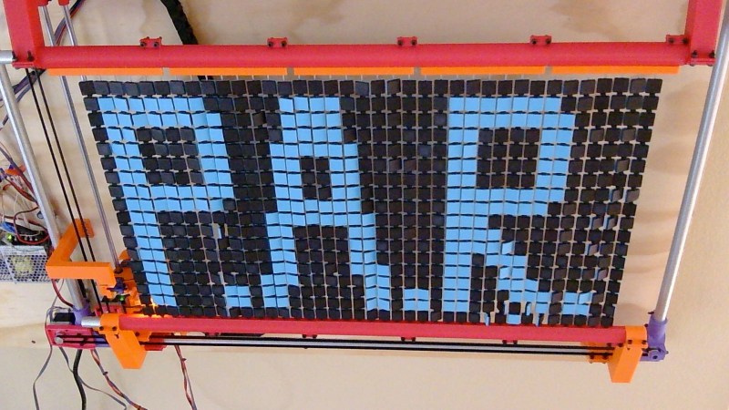
Flip disc displays can be quite a task to drive, what with having some sort of actuator mechanism for each and every dot in the display. [Zimm] has built an altogether different kind of flip disc display, though, which gets around this with a complexity all its own.
The idea behind the build is simple. There is still an array of discs, in this case, 37 x 18 square discs that are black on one side and blue on the other. However, they’re not actuated by magnets or any kind of per-disc flipper. Instead, a CNC machine is charged with flipping them one at a time. There’s a tool head that scans through the array, and uses a color sensor and LIDAR to identify which pixels to flip and how far to push them. It’s not fast, by any means, but it’s a perfectly cromulent way to build a flip disc display, as it turns out.
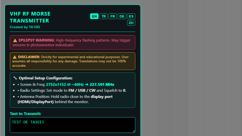
If you’re intending to transmit on the VHF band, you’re probably going to reach for a handheld or some kind of rackmount rig in your ham shack. But you needn’t bother with all that complexity, when you can use the computer on your desk to spit out such signals using a simple browser tool from [Efe].
The concept is straightforward—[Efe]’s tool manipulates pixel clocks in order to create spurious transmissions from your computer’s graphics hardware. The math pencils out pretty easily—multiply the horizontal resolution by the vertical resolution by the refresh rate, while paying attention to the precise timing of the video standard your monitor is using, and you’ve got your transmission frequency. For example, for a screen displaying 1080p at 60 Hz, with the CEA-861 timing standard, your horizontal and vertical resolutions are 2200 and 1125 respectively when paying attention to the requisite blanking intervals. Multiply those by 60 hz, and you’ll find you’re creating a signal at 148.500 MHz. Leverage this by displaying the right pattern of black and white pixels to maximise changes in voltage state on the HDMI or DisplayPort lines, and you might create a strong enough signal that you can actually pick something up. [Efe] created a tool to display these patterns to send simple Morse code messages over VHF just by flickering your screen just right.
You can test the transmitter tool for yourself here, right in your browser. You’ll want to hold your radio’s antenna nice and close to the monitor to see if you can pick up much of a signal. After all, the monitor, connectors, and cable are all built to optimize for clear signal transmission to the display, while preventing signal from leaking out to interfere with surrounding equipment.
Of course, a fair warning—you’re not supposed to intentionally transmit on bands you’re not licensed for, even if it’s incredibly weak and unlikely for anyone else to notice in a scenario like this. Still, it’s an interesting project that shows you just how electromagnetic interference can leak out of just about anything under the right conditions.
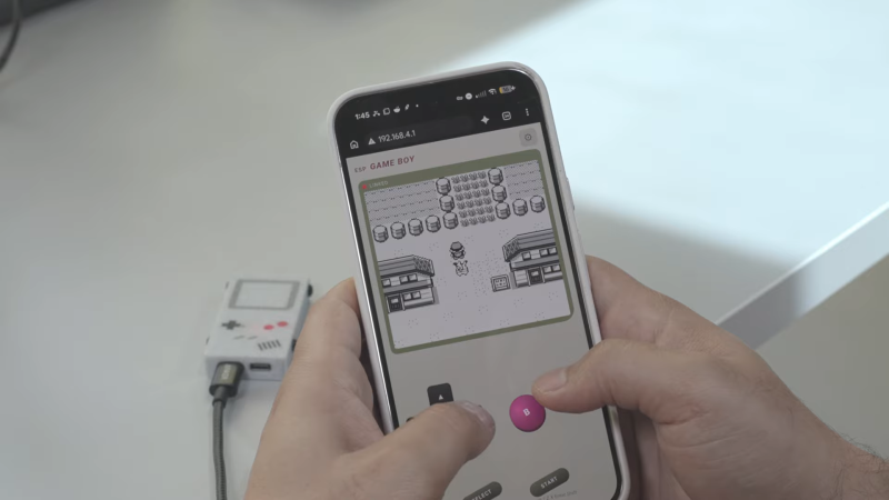
Since the Game Boy is a relatively simple 8-bit machine that runs at a leisurely 4 MHz or so, it is well within the capabilities of an ESP32 microcontroller to emulate. [Artificial-Age] got an ESP32-S3 and programmed it to do just that. However, there’s a twist—there is no screen hooked up to the microcontroller, nor any buttons. Instead, the board is accessed over a WiFi access point that it hosts itself.
One then opens a web browser, which streams the emulated video and audio from the console, while accepting button inputs from your keyboard or touchscreen, depending on the platform you’re viewing the web interface on. ROMs are stored on the ESP32’s flash storage, and can be uploaded via the web interface.
It’s an interesting setup, and one that perhaps doesn’t make obvious sense at first. After all, any modern smartphone can easily emulate a Game Boy, too. However, this setup makes it easy to share the emulator with other people, who can simply check out the WiFi AP and web interface without having to download or or install anything on their own device. We’ve featured some other fun emulation projects lately, too.

 Login
Login