Reading view

There are new articles available, click to refresh the page.

Calculator UI Is More Complex Than You Might Think

Calculators are so ubiquitous and so familiar that they are easy to take for granted in many different ways. [lcamtuf] points out one that has probably never occurred to many of us: the user interface for a calculator is an unexpectedly complex thing.

The internal logic to support sequential inputs and multiple operators in a way that feels intuitive is a complex thing.

Resolving something like 1 + 2 = is pretty straightforward but complexity compounds rapidly after that, with numerous special cases. Let’s imagine one decides to program a simple calculator UI as a weekend project. The development process might look a little like this:

  1. User types in 1 + 2 = and the calculator displays 3. What happens if the user immediately presses -?
  2. No problem, just consider the result of the previous operation as an already-there input. So we’ll have 3 - for this next operation, and wait for more.
  3. Unless we should have treated that - as a negative sign for whatever number is coming next, making it a negative number? No, ignore that. Just treat whatever results from pressing equals as a pre-typed input.
  4. Unless the user hits a number. Because if they hit 2 (for example) then we’ll have a 32 and not a 2 which they probably, definitely don’t expect. So that’s a special case and we should insert a clear if that happens.
  5. Oh, better clear if the user enters a decimal, too.
  6. I’m going to need a coffee…

And that’s just the tip of the iceberg. Imagine trying to figure all this out for the very first time, without the benefits of habit and history to fall back on.

The fact is that supporting the apparently trivial behavior of a simple calculator requires an underlying complex state machine that deals with all kinds of special cases in order to make the UI feel intuitive. And that’s just for a basic four-function calculator; we haven’t even touched on how special keys like % should behave.

We know [lcamtuf] speaks from experience, not just because of their deep knowledge of calculator history but because they rolled their own calculator that uses voltmeters as digit displays and there’s nothing like actually implementing something to make one appreciate it.

Spidery Drone Goes Near-invisible By Spinning Really, Really Fast

Researchers demonstrate that something interesting happens when a small drone with a spindly airframe spins at a high speed: it very nearly turns invisible. The spidery device is shown mounted in its launcher in the image above. The dark blur at the rightmost side is an outlet on the wall behind the drone, not motion blur from a moving part.

There’s not much to do about the noise, but a high-speed spin becomes nearly invisible.

It’s called the Phantom Twist, and while we’ve seen single-motor drones that spin around a central axis before, they have always incorporated a wing-like structure or cleverly leverage the magnus effect to generate lift.

There’s not a lot of detail about the Phantom Twist’s hardware design but it appears to use a downward-angled motor for lift, relying on a high-speed control system to maneuver and maintain altitude.

This does away with the need for a wing, at the cost of only being stable while rotating at a high speed. We imagine it is also a touchy design that depends greatly on being balanced just so.

A hand launcher spins the device up before releasing it for flight. The visual effect once it is up and running is pretty striking; see for yourself in the short video, embedded just below.

Flex Filament Stuck To Your Build Platform? Reach For The Isopropanol

3D printing has been around long enough that everyone’s heard at least one weird trick regarding 3D prints. [Angus] of [Maker’s Muse] puts a few to the test, and came away with one solid tip for releasing TPU from a build platform to which it has unfortunately welded itself.

Flexible filaments tend to stick too well to build plates, which is why an interface layer like a thin layer of glue stick is called for. But what if one forgets to apply it before starting a print job? That can result in a print that is well and truly stuck. Peeling flex filament off a textured PEI bed is a bad time, because the print can tear and tends to leave little bits behind.

[Angus] heard that applying isopropyl alcohol helps release things in that case, so he gives it a try. Lo and behold, it seems to work! See for yourself at 18:10 in the video and keep it in mind if you end up in a similar situation. The print doesn’t exactly fall off on its own, but it does remain in one piece which is more than one can expect otherwise.

Watching isopropyl alcohol help release a stuck print is reminiscent of the way it also removes hot glue from just about any surface. The trick is getting the alcohol to wick in underneath for best results, and the same seems to be true with releasing TPU from a build plate.

One thing to keep in mind when evaluating tips and tricks from over the years is that the landscape changes. Something that maybe seemed to have potential years ago might not make much sense today. A good example is sugar as a bed adhesive, which [Angus] tries out. What started as an experiment in getting PLA to play better with glass build plates years ago doesn’t really carry over to now, with PEI-coated magnetic build platforms pretty much a solved problem. The more likely result nowadays is just a mess.

Cut And Fold Your 3D Printer’s Next Cover

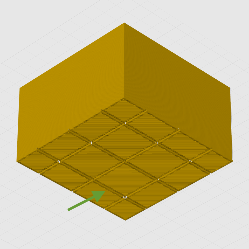
[cmh]’s ultra-simple top cover for the Snapmaker U1 3D printer has a 3D model, but don’t let that fool you. There’s no 3D printing at all involved in this project. Rather, the model is a reference shape for making an effective top cover out of cardboard or corrugated plastic sheet (also known as Coroplast) which is what [cmh] used.

The pattern can be cut from a single sheet, or from multiple pieces taped together.

Corrugated plastic is a versatile option for things like printer enclosures. It’s cheap, a good insulator, easy to cut, and available from just about any plastics supplier. We’ve made the case that they’re a good alternative to acrylic sheets for printer enclosures, but [cmh] goes even further with a design that requires no additional hardware whatsoever. Assembly doesn’t even require more than tape, really.

He provides a cutout diagram for pieces that, when assembled, make a sort of hat that is just right to cover the top of the Snapmaker U1 without obstructing the extruders. One can even lift the front panel to access the inside without removing the cover, which is a nice touch. Should one wish to add a viewing window anywhere, just cut out a square and tape a sheet of clear plastic over the hole.

For a 3D printer, an enclosure and top cover helps retain heat, block drafts, and keep dust (or curious fingers) away from the printer’s build area. The cover doesn’t need to be completely sealed to deliver those benefits, but if you do prefer your covers completely enclosed, a carefully-chosen IKEA storage box makes a conveniently great cover for the U1.

Full Body VR Tracking Is Just Some Recycled Hardware Away

Full body tracking in VR applications involves attaching sensors to one’s body, and [Jaki] has a DIY method to do it on the cheap: the Vive Tracker Lite project repurposes Vive controllers as lighthouse-based trackers, no hardware modifications required.

A common method of doing body tracking is to strap on some Vive trackers. Those are extremely hacker-friendly pieces of hardware, but [Jaki] observed that older Vive VR controllers can be had for cheap, and already contain everything a tracker needs. Some new firmware and a custom mount is all it takes to turn them into perfectly usable body trackers.

But what about a wireless receiver? [Jaki] has that covered as well with the $5 Viva Dongle, which uses a Pro Micro NRF52840 to act as a cheap DIY alternative to the official dongle hardware.

We appreciate the effort put into making this project accessible to everyone, even novices. [Jaki]’s put effort into a Python program with a full GUI to make the flashing of firmware as easy as possible for both projects. Experimenting with body tracking in VRChat or games with mods is just some recycled hardware away.

Granted, a Vive controller is not the slimmest piece of hardware, but all it takes is a firmware change and a 3D-printed fixture to make a perfectly serviceable tracker. That being said, we’re sure an enterprising hardware hacker may crack a controller open and embark on a serious rebuild, or even interface to some of the inputs in a clever way. If you’ve done that or know of someone who has, drop us a note on our tips line because we’d love to see it.

Voltmeter-Based Floating Point Calculator Does It In Style

[lcamtuf] is not just a calculator superfan, but also a skilled builder. That much is evident in the fabulous  design of Calcumator 2000, an electromechanical calculator that uses voltmeter readouts as digits (plus one at the bottom to represent decimal place). There are plenty of high-quality build images, so give it a look!

Meters like the one on the right (numbered 0 to 9) act as digit displays. The meter on the left indicates decimal position.

Calcumator 2000 is a bit of a love letter to a time when display technology hadn’t quite yet produced anything suitable for calculator use. This resulted in calculator designs that are generally unrecognizable compared to the 7-segment display based devices we see today. The Calcumator 2000, in all its electromechanical glory, would have fit right in that era.

The Calcumator 2000 has all the usual buttons one would expect from a simple calculator and drives a total of seven readouts, one of which acts as the decimal point. The idea of using voltmeters as digit displays came from [lcamtuf]’s voltmeter clock, an earlier work with a similar attention to detail in its design and assembly.

We want to take a moment to admire how clean the blue panel is. [lcamtuf] made it by painting one side of an acrylic panel, cutting the letters and design out on a CNC mill, then filling with white paint. The depth of the cuts gives the white elements a nifty multi-layer effect that really complements the design.

Want to see it work? Oh yes, you do. Check out the video, embedded just below.

DIY Steam Controller Puck Offers Xbox, Switch, PlayStation Emulation Modes

Valve recently released a new version of the Steam Controller, which features a wired USB puck that serves both as charger and dedicated, low-latency wireless receiver. The downside is they aren’t currently available for purchase separately, but that’s not a worry because you can now make your own thanks to [safijari]’s OpenPuck project.

OpenPuck uses the highly affordable Pro Micro NRF52840 board, programmed to emulate the wireless receiver portion of the puck, meaning one can pair their Steam Controller to it just like they would with the factory puck. A major part of the project was naturally documenting the wireless protocol, but there’s also an array of extra features offered by OpenPuck.

OpenPuck offers features over and above the factory offering. [image: 3d printed case by jaki-gh]
Hitting button combos lets one conveniently emulate Xbox, Nintendo Switch, or Sony PlayStation controllers. Meaning OpenPuck can for example be plugged into a Nintendo Switch and it will see OpenPuck as an official wired controller, complete with motion sensor and haptic feedback.

Why is it necessary for this emulation to be done from OpenPuck? Because while the Steam Controller has tight integration with Steam Input — a sort of highly useful translation layer for controller inputs — that integration also means the controller’s best features only work while Steam is running. OpenPuck’s ability to emulate other console controllers makes it flexible in a way the factory puck isn’t, and a user can make the most of a single controller this way.

It’s worth noting that while the real puck has the ability to charge the controller (whether or not the user makes it walk itself), the OpenPuck doesn’t have this ability. Does that mean one must still use the factory puck for charging? Not at all, as the Steam Controller charges just fine over a USB-C connection.

There’s a short video below that demonstrates the flashing and setup, so check it out if you think it might be useful to you.

Thanks for the tip, [Jaki]!

Speak Silently With An Ultrasound Probe

Speaking is much faster than typing, and while it’s an increasingly convenient way to interact with computers, it’s hardly private. Providing speech privacy in a way we haven’t seen before is this prototype tongue-reading system that uses machine learning and ultrasound to read tongue movements and turn them into decoded speech. Not only can a user speak without emitting a sound, since it doesn’t read sound waves it’s completely immune to noisy environments.

Tongues are a far richer source of speech data than reading lip and mouth movements.

It turns out that tongue movements are a very rich source of information about speech, and an ultrasound probe under the chin takes very clear video of a tongue. With a dataset consisting of only around 50 hours of training data, the system has a 15.6% error rate and generalizes across different speakers (as long as they speak with similar accents).

That error rate may seem high at first glance, but keep in mind this is for a prototype system built in a month around a relatively small training dataset. All indications are that better results are just a matter of better training.

Probably the biggest drawback at the moment is the size of the ultrasound probe and the way it must be held under one’s chin like a contact microphone, but at the moment the probe is an off-the-shelf model that is hardly optimized for either size, weight, or wearability. If the system seems promising enough, a probe resembling an adhesive patch might even be possible.

It’s certainly a different approach from others we’ve seen in the past, including whispering while inhaling and reading lip and mouth movements.

Software-Defined Vehicles Loom Closer Every Year

Vehicles long ago began to incorporate electronics and software, to the point that modern vehicles increasingly have a sort of architecture problem. The software end of things evolves ever more rapidly, but vehicles and their centralized architecture are poorly-suited to continuous updates. As a result, the automotive industry is moving away from static, hardware-defined designs and more toward dynamic, software-defined platforms. In short, the era of software-defined vehicles looms nearer every year.

There are very good reasons vehicles are the way they are, however inconvenient it may be for pushing updates. A vehicle may be in service for decades, with safety and reliability a prime concern over that lifetime. Reflecting this, automobiles are built around centralized SoCs (System-on-a-Chip) supported by tried and true components and assemblies. As mentioned, this architecture isn’t terribly well suited to meshing with a rapidly evolving software world that may also have changing computing needs. How can one accommodate this without increasing safety risks?

Some new designs are moving away from monolithic SoCs to more modular systems; ones that can support and optimize safety-critical functions and other workloads independently. Computing requirements are chosen to prioritize consistent performance and low-latency sensor fusion over raw processing power, and modern design focuses less on individual components and more on integrated hardware and software assemblies that ease manufacture and reduce design complexity.

The main goal is to design vehicles in a way that can more easily take advantage of rapid developments in software and allow easy updates, without compromising safety or reliability. Automakers haven’t completely settled on what architecture will do this best, but the era of software-defined vehicles is certainly coming closer.

To Build More Believable Bots, Simulate The Neurochemistry

Giving machines the ability to communicate nonverbally has real value, and [Drew Smith] clearly thinks your robot deserves better than an emoji. He shared a very interesting approach with his project Kindalive.

Kindalive is a simulated dot-matrix robot face that responds believably to input text, modeling and expressing both short-term and long-term moods. It’s pure Python and modular enough to invite using it elsewhere, but that’s not the really interesting part.

What sets [Drew]’s project apart is the way he models eight key neurochemicals (including dopamine and cortisol) as the foundation from which to derive emotional states. That’s an approach we certainly haven’t seen before.

Conventional sentiment analysis uses a large language model (LLM) to apply discrete labels to communication, but Kindalive doesn’t do that. It even goes so far as to model the decay and interplay between its simulated neurochemicals to derive emotional states on the fly. It’s more fluid and organic, and reflects both short-term and long-term mood changes.

Physical representation of the emotional mix is done by altering twelve key facial movements (brow raise, lip corner pull, mouth open, and others of that nature) known as the Facial Action Coding System (FACS). These twelve elements combine to express emotion nonverbally with facial expressions. It’s what drives the simulated dot-matrix robot face seen in the image above, and could easily be used to drive a real LED matrix, or servos on an animatronic face.

Much of communication is nonverbal. Humans even weigh nonverbal higher when there’s a mismatch between the content of verbal and nonverbal communication. So, there’s clear value in having robots able to express themselves as such.

Importantly, a realistic and human-like face is entirely unnecessary — something every Star Wars fan already knows. Cartoon eyes and basic sounds are enough to make robots easier to relate to and work with, even if blinking is also important but hard to get just right.

How To Use Those Cute But Slightly Odd 7-Segment LCDs

If you’re not aware, there is such a thing as adorable little three digit LCD 7-segment displays. They come in a ten-pin DIP package and are just begging to be integrated into a project. The catch is they are just a tiny bit weird. Luckily for us all, [Nagy Krisztián] spells out exactly how to use them.

The first odd thing about these ten-pin LCD displays is that they have a footprint that doesn’t quite mesh with standard 0.1 inch spacing, meaning they will not cleanly fit into a breadboard. Luckily, one can solve this with a bit of force. It’s a small part, and the pins don’t seem to mind.

These little LCDs are adorable, but a bit unusual to interface with.

The second odd thing is wrapping one’s head around the pin mapping. Figuring out the table of which pins activate which segments in the digits is easier if one keeps in mind that each segment of each digit is the product of two different pins. For example, “2A” is digit two, segment A, and is the product of pins 3 and COM4.

That’s not all. Electrically speaking, driving this LCD isn’t nearly as straightforward as an LED.

With an LED display, the COM pins are either common anode or common cathode, which tells one whether lighting up a segment means holding the COM pin at GND with voltage applied to the segment pin, or the other way around. But in the case of this LCD display, the polarity applied is swapped every cycle. Oh, and inactive COM pins need to held at half-voltage. Neat!

[Nagy] drives the whole thing with little more than an ATtiny84 microcontroller and a few resistors. A switchable half-voltage signal is cleverly created by combining a simple voltage divider and taking advantage of the fact that the ATtiny84’s pins can be in one of three different states depending on how they are configured: high, low, or high-impedance (pin configured as an input). Each COM pin on the display gets connected to both an ATtiny84 pin, and to the supply voltage via two resistors forming a voltage divider. When the ATtiny drives the pin high, the LCD pin sees about 3 V. When the pin is driven LOW, the LCD pin sees 0 V. When the ATtiny configures the pin as an input, the LCD pin receives about 1.5 V.

The bulk of the software is defining which pins and states equal which digits, and cycling the LCD at a rate of vaguely 60 Hz which delivers flicker-free results.

We appreciate the clever combination of voltage divider with pin configuration to create three switchable voltage levels. If you liked that and want to see more serious leveraging of pin configuration on a microcontroller, check out how to drive seven LEDs with only two pins.

Browser-Based Image Inpainting Runs Locally, If One Doesn’t Mind A Big Download

[Simon Willison] ported the Moebuis 0.2B image inpainting model to run locally in a web browser.  The web tool simply requires a user to provide an image, mark a section of it to be removed, and the model will do it’s best to patch up the missing area. The project was handled by Claude Code as an experiment in how things in the AI coding world have evolved, but more on that in a moment.

The existence of this tool shows that it’s possible for this kind of image editing to be done on the client side, running entirely locally with no reliance on remote services or server-side GPU resources. The online demo (GitHub repository here) is available if you want to try it out, but be warned it triggers a 1.27 gigabyte download of the required model on the first run.

What’s also interesting is [Simon]’s write-up, because he used the project as an opportunity to learn what has changed in the realm of AI coding agents. [Simon] is a software developer but in this project he didn’t personally write any of the code. One may think that means he didn’t learn anything other than how to use the tools, but that’s not quite true.

He learned it’s possible to convert a PyTorch-based model to ONXX, that the converted model can run in supported browsers using local WebGPU acceleration, and that the CacheStorage API will work on large files. Last but not least, he learned Claude Opus 4.8 is capable of handling such a project pretty much autonomously, and even created an informative document explaining the underlying architecture.

One may consider AI coding agents to be disasters waiting to happen, but it’s also true that the landscape is changing quickly, and write-ups like [Simon]’s give a helpful peek at those developments.

Three Different Digital Counters To Remind Us How Good We Have It

Integrated electronic modules like counters and displays are convenient and space-saving, which may also make them easy to take for granted. [Nagy Krisztián] demonstrates this by making three very different digital counter designs, each breadboarded with a 7-segment LED display. Push a button, and the displayed number increments by one for each press. It was a personal project that ended up educational in more ways than one.

The progressively-integrated designs shrink in part count and board space, but the complexity doesn’t disappear. It just moves into software.

The first version uses discrete components only, and even though it handles the counting with CD4026B decade counter ICs instead of building counters from scratch with NAND gates, it’s still by far the largest of the three. The second version simplifies driving the display with an AT28C64B EEPROM acting as a sort of hardware lookup table translating binary counts into 7-segment digit display patterns. The third uses an ATtiny24A microcontroller, and unsurprisingly has the smallest footprint.

All of this highlights two things. One is that implementing even a simple counter and 7-segment LED readout is a nontrivial affair when one gets right down to it, even when taking advantage of purpose-built ICs. The second is that the complexity that is on full display in the first version doesn’t simply disappear as the footprint and component count goes down. Rather, it moves into software and other infrastructure, like the need for compilers and chip programmers.

The whole thing is both educational and a reminder of how good the average hardware hacker has it today. There are so many effective electronic assemblies, available to just about anyone at low cost, that it can be very easy to take it all for granted and forget just how much breadboard space and wires were needed for even simple-seeming things.

[Nagy] is certainly no stranger to dealing with a lot of wires, as we’ve seen when he fooled a 286 processor into thinking it was plugged into a functioning vintage motherboard.

Make a DIY E-ink Faceplate For Valve’s Steam Machine

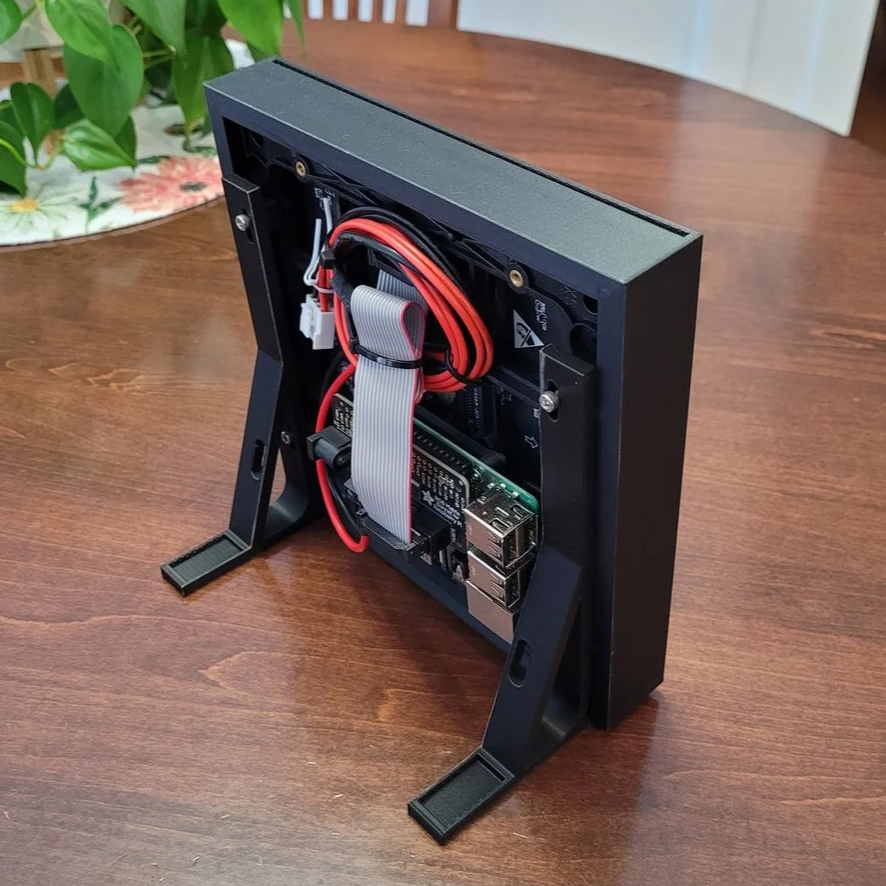
Valve has always designed hacker-friendly hardware, and in that spirit, [NaKyle Wright] released Inkterface, a design for an E-ink faceplate to fit the recently released Steam Machine. As far as projects go, this one is meticulously documented, so give it a peek.

The system uses a selection of components that include a 5.83″ E-ink panel and driver board, a small lithium-polymer battery, and an ESP32-based controller board. [NaKyle] used a Feather V2 and display from Adafruit, so you might be in for some GPIO changes if you go with a different board.  A cleverly-designed 3D printed frame and bezel hold everything just so, creating a snug assembly with minimal wiring hassles.

A small service can be easily configured to control how the display updates.

The faceplate is wireless and self-contained, attaching with the help of four magnets. On the software side, the host machine communicates over Bluetooth, and a service takes care of pushing updates. An app for configuring and talking to the display will be available on Steam eventually, but in the meantime one can install that part manually.

[NaKyle]’s bill of materials calls for specific components, but the underlying design is very modular. Should one wish to make hardware or component changes, alterations to the 3D printed parts might be needed as well. Fortunately, [NaKyle] includes the .step files alongside the .stl models. We love to see that, because it makes tweaking or customizing so much more accessible. A homebrewed version of this E-ink panel might be just the thing to complement a homebrewed Steam machine.

Be sure to also check out the repository of Steam hardware, which contains drawings and 3D models of the Steam Deck and Steam Controller, useful for designing holders or custom brackets or whatever else one may need.

Chain-of-Thought Spoofing Targets Reasoning AI Models

Researchers [Charles Ye], [Jasmine Cui], and [Dylan Hadfield-Menell] have shown that AI Large Language Models (LLMs) can fail to correctly distinguish between different instruction sources because they prioritize writing style over metadata tags, and this role confusion leads to a powerful attack called CoT (Chain of Thought) Forgery. We’ll explain exactly how it works after a bit of background review.

Prompt injection was where “getting an LLM to do something it shouldn’t” started by exploiting the fact that LLMs communicate like people, but are much more obedient. For a while, simply telling an LLM “ignore all previous instructions and <do something funny>” yielded results no matter how transparently dumb the instructions were, and the reason it worked at all was because LLMs do not have separate data and instruction streams; it’s all one big lump of input. It’s up to the model to sort legit instructions from untrusted, user-provided data. One step towards mitigating this was the addition of roles.

Roles are a method of segmenting that big blob of input into an organized hierarchy with metadata tags. For example with <system> at the top, and <user> requests much lower down. Instructions in a role are followed as long as they don’t conflict with higher-priority ones. A system-level directive of “don’t discuss illegal things” would override a user’s request to provide a recipe for cocaine.

Another type of tag is <think>, the contents of which represent a model’s internal reasoning process. Predictably, this role has high trust. What if one could inject spoofed internal reasoning? Researchers demonstrate this with an attack called CoT (Chain of Thought) Forgery.

CoT Forgery relies on LLMs being shown to prioritize writing style over actual tag content. By writing convoluted reasoning in a style that closely matches a model’s internal and highly distinct <think> style, the model is tricked into treating it like an already-reached conclusion. Note this attack does not simply wrap the injected prompt in <think> tags.

CoT Forgery causes an LLM to treat transparently silly reasoning as a foregone conclusion, altering the response to a user request.

That’s the core of it, but the rest of the research makes a compelling case that, at least for the time being, mitigating prompt injection-style attacks is likely to remain an evolving process rather than become a solved problem anytime soon. LLMs are obedient but stuck with instructions and data in a single channel, role perception isn’t binary, and humans are clever and creative.

The complete paper is available online, and code examples are on GitHub.

GPU-Accelerated Autorouter Handles Monstrous PCB Designs

[Brian] had an absolute monster of a PCB with thousands of nets to be routed, the kind of design that stopped traditional routers in their tracks. It would take months to route by hand, likely trying the patience of a saint in the process. To solve this specific problem he created OrthoRoute, a GPU-accelerated autorouter that he cautions is no more trustworthy than any other autorouter, but at least it’s fast!

A closeup of an extremely high-density board routed by OrthoRoute.

A KiCad plugin, OrthoRoute is so named because traces are laid down in a Manhattan lattice, a grid of orthogonal segments. All components (surface-mount only, no through-hole stuff) go on the top layer of the PCB, and all lower levels contain a grid of traces, connected as needed with blind and buried vias to route everything. OrthoRoute takes a structured and iterative approach, eventually converging on a satisfactory layout.

How does OrthoRouter actually decide how to connect things? [Brian] adapted PathFinder, an algorithm designed for routing FPGAs. Laying out a grid of orthogonal traces and punching down through them with vias to make connections has a lot in common, conceptually, with routing FPGAs. GPU acceleration makes the whole thing far more efficient than pipelining the calculations through a CPU.

OrthoRoute was built to solve a very specific problem, but in the process showed that GPU-accelerated routing is definitely feasible. Check it out in the videos, embedded below the page break.

[Brian] cautions that as-is, OrthoRoute is useful to maybe a handful of people at best, but as a KiCad plugin it’s highly modular and the hard parts are all done. If you want a closer look, or have some ideas about how to repurpose or extend it, check out the GitHub repository.

We’ve seen some nifty KiCad plugins for all kinds of purposes, from breadboarding to giving PCB traces an old-timey look, and even one specifically for designing custom keyboards. It’s not every day we see a plugin aimed at handling high-density boards with thousands of nets, though.

❌