The 2026 Hackaday Superconference is just around the corner in November. It’s hard to believe that we’ve been having an annual gathering for so long, but this is number ten. Every year, it’s a great time to refresh your pool of new ideas, hang out with fellow hackers, put your soldering skills to the test, eat some phenomenal tacos, and catch some of the two tracks of talks.
What’s got me stoked right now is that we just finished up talk selection, and this year is going to be a banger! We had more talks submitted than ever, and all of high quality. Frankly, if this keeps up for next year, we might have to figure out a third stage.
This year also marks the move to a bigger venue, with more space for hacking in the courtyard, more space for talks in two halls, and more room for you to all settle down and share your work, or create something new. Even the badge is going to be bigger this year – but that’s all we can say at this time.
If you don’t have your tickets yet, go ahead and get them. Flights are still relatively cheap, and hotels not booked up yet. See you all soon!
This article is part of the Hackaday.com newsletter, delivered every seven days for each of the last 200+ weeks. It also includes our favorite articles from the last seven days that you can see on the web version of the newsletter.
Want this type of article to hit your inbox every Friday morning? You should sign up!
Erin Kennedy has been building robots for over a decade now, with a focus on smaller bots that interact with, or maybe even clean up, the outdoor environment. Still other bots are made to interact with people, and when the people are outside in the park, that’s where your robot needs to go.
Whatever the reason, Erin’s talk at Hackaday Europe 2026 is an invitation to take your projects out into the outdoors. But the great wide world outside of your lab is not necessarily the most friendly place for a little bot, and the other half of this talk is about practical design tips and lessons learned to help it survive.
Environments
She structures the talk around different environments, which gives her an opportunity to focus on her bot cleaning up plastic trash on the beach, but also to point out the absolute horrors that sand can work on robot motors. She goes through a number of strategies for dealing with this, including going slow, keeping the motors as high up as you can, and designing the body of the robot to be full of holes and shed sand.
Taking to the water, she demos Otter Force One, which aims to capture invasive sea urchins. But underwater means under pressure, and she gives us some good tips on how to get the cables out while keeping the water in – double-o-ring cable glands potted with marine epoxy. I especially love the Nalgene-bottle-on-a-string with a radio that can be deployed to help retrieval. Her lessons-learned section is as deep as it is understated, including underwater hazards from low visibility to accumulated silt messing up your presumed center of gravity. Over the long term, rubber leaks and barnacles accumulate. Double seals, durable hooks, tether ropes, and bright colors are your friends. Underwater bots have it hard.
Erin’s air-inspired bots are the wildest. Some are just whimsical, like the flappy square bird, or beautiful like the butterfly bots. But her Atmosphinder bot uses the wind for actual propulsion. It’s a rolling wheel with sails that aims to explore long distances on Mars. Whether it’s going to get there or not, it’s got a bunch of great design elements for anything you have that’s going to have to roll. “Magic toboggans” make great plastic sails. But beware, while you can turn off a motor, you can’t turn off the wind. Be prepared to stake your bot down before or after its mission.
Experiences
Whatever the environmental challenges of taking your bot outside, it’s the non-laboratory environment that’s the most challenging, and rewarding. Erin tells the story of when a bird settled down in the shade cast by Bowie, or when the wind blew all of the Aruco markers away. But people and animals are just as delightful and unpredictable as the weather, and that’s an extra level of adventure. If you’re going far, bring hydration for the humans and spare batteries for the bots. Rolling with the changes seems to be the key to having a good time outside with your bots.
And of course, bringing your robot outside is a great opportunity to share what you’ve been working on with the offline world. We absolutely love the mission: normalizing robot hacks among the general public by hanging out with your bot in the park is right up our alley. She has had tremendous success with random encounters – folks just coming up and asking about what it’s doing. Making your bot seem friendly and/or beautiful seems to go a long way here. Don’t neglect the aesthetics.
Take Your Bot Outside
We left Erin’s talk absolutely inspired to build something that can make it through the rough environment that lies just outside our basement. It reminded us of our old days experimenting around with BEAM robotics, another bio-inspired practice aimed at the outdoors. With 3D printable parts and cheap geared motors, you don’t even have to break the bank to build your own Mars neighborhood rover. Watch this talk and get inspired!
Oftentimes, when we’re using a microcontroller, we’re whipping up some very specific code focused on executing a particular task. The device is set up to execute code that does exactly what we want with minimal overhead. However, sometimes, there are scenarios where it pays to go with a somewhat heavier setup, wherein the microcontroller runs an operating system for the benefits that offers.
Federico Terraneo came to Hackaday Europe to discuss this very topic. He talks about kernel architecture, real-time operating systems, and how to best use C++ in the world of microcontrollers.
Microcontrolling
The talk begins in a helpful place. Federico starts by explaining what an operating system actually is. Basically, it’s the software that exists between the hardware and the applications that run upon it. Breaking it down into parts, an operating system typically consists of a main kernel, atop which sits things like the basic system services, libraries, and device drivers, along with utility programs necessary to maintain and work with the system. The user interface sits on top of all that, which allows the user to select and run applications and generally use the operating system to get things done.
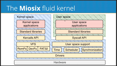
Federico talks about the Miosix RTOS as a practical implementation of the fluid kernel architecture.
Of course, different operating systems differ in the specifics of their architectures. Monolithic kernels, such as Linux relies on, keep a split between kernelspace and userspace. This is where where the kernel has full hardware access running on the CPU in system mode, while the applications run in user mode without such direct access. Monolithic kernels typically only run on architectures with memory management units (MMU)—think full-scale computers with proper CPUs, like your laptop or desktop. Unikernel operating systems, like FreeRTOS, are a little different, where applications and the operating system are collapsed down into a single executable binary that runs with raw hardware access. There is no abstraction, no memory protection, or anything like that, which makes the architecture easier to run on typical microcontrollers. There are also microkernels, which aim to minimize the amount of code that runs in system mode, pushing things like drivers and filesystem access into userspace. This architecture still needs an MMU, and is mostly only seen in niche uses where high security and/or attention to safety is critical.
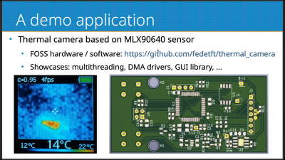
A thermal camera running on a fluid kernel system serves as a great demo application for the platform, showcasing several important features like multithreading and DMA.
When it comes to microcontrollers, unikernels are the most relevant architecture to think about. However, they have limitations–in stability, in security, in the fact that there is no run-time code loading or any way to easily partially upgrade the system. The fluid kernel, which Federico came to explain, aims to solve some of these issues. It hopes to offer a scalable operating system solution that works across the world of embedded computing, where sometimes microcontroller resources are limited and where memory management units seldom exist. It’s also intended to be compatible with standard APIs—think POSIX, C++ standard libraries, and all that. Federico calls it the “UNIX on a chip” concept.
The fluid kernel aims to exist at the intersection of the monolithic kernel and the unikernel. It allows hosting applications in kernelspace or in userspace as needed. A fluid kernel is also built to be POSIX compliant twice—with the same API whether you’re operating in kernelspace or userspace. The fluid kernel concept is designed around achieving process abstraction via the hardware Memory Protection Unit (MPU) common in modern 32-bit microcontrollers. It’s not quite an MMU, and can’t do all the same fancy virtual memory tricks, but it’s enough to provide a basic level of memory protection on a microcontroller platform. The fluid kernel can also become a unikernel if so desired as a compile-time option, which takes away process support while reducing code size significantly. It allows for unikernel devleopment that can be upgraded into a fluid kernel later by flipping the compile-time option the other way.
Federico does a great job of explaining the pros and cons of the fluid kernel architecture, and explores the security implications inherent in going this route. The Miosix RTOS is discussed as the practical implementation of this philosophy, and there’s even a helpful diversion into the efficient use of C++ on microcontrollers. If you’re getting serious about embedded development, or you just want to learn about a new architecture you might find useful one day, it’s a great talk to dive into on your next lunch break.
There are many ways to detect stress in an individual. You can use self-reporting checklists, you could try and measure various vital signs like respiratory rate and pulse and infer things, or you could observe the levels of hormones like cortisol in the blood.
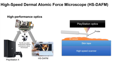
Or… you could pull some parts out of a Playstation 4, and get hacking. Edwin Hwu did precisely that, creating a device that can image the skin down to the nanometer and potentially even determine fine details about an individual’s health status. He came to Hackaday Europe 2026 to tell us all about it.
Look Closely
Edwin’s background is very relevant to this project. He worked in a research institute in Taiwan where he collaborated with the German National Metrology Institute, working on atomic resolution imaging on silicon wafers. When you’re doing sub-nanometer calibration work for the semiconductor industry, that’s serious stuff, as is the X-ray microscopy that Edwin has dived into. When it comes to looking at things at very tiny scales, he knows his stuff. He’s also done plenty of work on real-time cell culture monitoring, skin assessments, and even high resolution 3D printing. It’s a broad skill base that all fed into the project he came to Hackaday Europe to talk about.
A single strand of DNA imaged with a DVD-based AFM setup. Credit: talk slides
There is a problem with optical microscopy that comes down to the diffraction limit of light—which means you can only image down to a resolution of around 1 micrometer. That’s why we use scanning electron microscopes for so many finer tasks, because the diffraction limit of electron beams is so much smaller. This allows the imaging of structures like carbon nanotubes or buckyballs, but with the limitation that the surface must be conductive and the imaging be done in a vacuum environment. A newer technology is the atomic force microscope (AFM), which involves using a very sharp probe with a tip of just 2-3 nanometers to actually touch molecules. This can be done without a need for a conductive surface or vacuum. When taking this approach to look at things on the nanometer scale, Edwin likens it to trying to poke a 1 euro coin with the tallest mountain on Earth. It’s a precise device with incredibly high resolution, but the average AFM costs half a million euros, and is incredibly bulky and slow at what it does. That is, unless… you find a way to build one on the cheap.
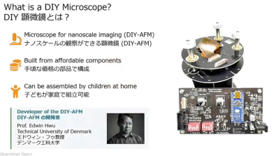
Atomic force microscopes were once incredibly expensive and cumbersome pieces of laboratory equipment. Now, it’s possible to build one yourself from an affordable kit, and it’s easy enough for children to put together. Credit: talk slides
Some time ago, Edwin created an atomic force microscope using the optical head of a DVD player, achieving a resolution of 0.39 nanometers. With this build, it was possible to image a single strand of DNA. Edwin also talks about how he used simple piezoelectric buzzers to create an ultrafine scanner for this work. The piezo elements are used for actuation, since they can be controlled to make incredibly minute movements. The work developed to the point where DIY AFM kits were made available at a mere fraction of the cost of traditional laboratory-grade installations.
The Playstation 4 proved to be the perfect donor for a high-quality AFM build thanks to the performance of the Blu-Ray optical head. Credit: talk slides
This work spawned a greater plan. Through his talk, Edwin explains how he figured out that e-waste gaming consoles could be turned into cutting-edge atomic force microscopes. Specifically, the Playstation 4 was the perfect candidate, with its high-end Blu-Ray optical head which is capable of reaching the diffraction limit of light. The Blu-Ray optical head is used to monitor the movement of the AFM probe, while scanning it is achieved with a piezo rig just like the earlier DVD-based build. It also has the benefit that the Blu-Ray hardware is built for higher data rates, meaning it’s possible to stream data from the optical head much faster for a quicker AFM scan. Edwin refers to his build as the HS-DAFM—for High Speed Dermal Atomic Force Microscope—since it’s 100 times faster than traditional laboratory atomic force microscopes.
By looking at the skin at a nanoscale level, the tool is useful for investigating conditions like atopic dermatitis, among others. Credit: talk slides
The word “dermal” is important—because Edwin has put the build to use in examining skin nanotexture, for diagnostic purposes. His talk explains how, combined with machine learning systems, the tool can be used to investigate skin conditions and help in the diagnostic process. It’s also become useful from the perspective of cosmetics, and looking at how the skin looks at the nanoscale due to factors like aging and UV exposure. With the aid of machine learning tools, Edwin has found that it’s even possible to determine if someone has asthma with 75% accuracy, just from a skin scan. There is even an exploration of mental stress versus skin nanotexture, albeit in a very preliminary stage.
If you’ve ever wondered about the finer details of doing atomic force microscopy on the cheap, or how skin texture holds the secrets of so many health-related matters, Edwin’s talk is a great one. Sometimes thinking outside of the box and the limitations of commercial laboratory equipment can lead to wonderous things, as it did here!
Printed circuit boards were developed first for function over form. They were a way to mount components and connect them in a stable, robust fashion, while taking into regard things like packaging and cooling requirements to enable a circuit to function. Circuit boards often end up looking cool in a techy kind of way, but their aesthetic is usually very much secondary to their actual purpose.
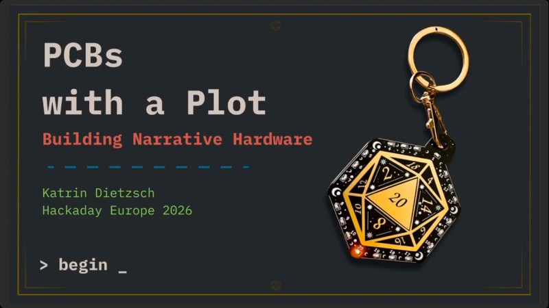
Katrin Dietzsch likes to use her PCBs a little differently, however. She designs boards that are intended to be a narrative tool for tabletop roleplaying, and came down to Hackaday Europe 2026 to walk us through the development of this very whimsical hardware.
Roll For It
Katrin starts her talk by explaining how she came to design circuits specifically for tabletop gaming. She saw an opportunity to combine her hardware hobby with the world of TTRPGs to help maintain both hobbies amidst a busy lifestyle. She also found that hardware she built could be a great artistic medium for supporting mystery and storytelling in the tabletop world. With the right design, her circuits became very much part of the narrative themselves.
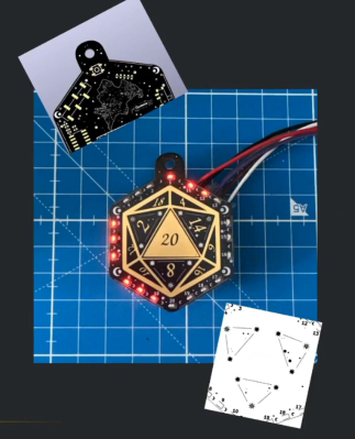
Getting to see Katrin’s PCB D20 is a highlight of the talk. It’s a great example of creative board design.
How does one create a piece that becomes special, rather than just being another art project thrown in a drawer, though? Katrin notes that meaningful objects are the ones that gather stories about them and gain emotional baggage, and thus, relevance. Interaction is also key; she relates the familiar tale that many of us have yelled at a printer before. We often anthropomorphize objects or assign them personalities just because they have some level of strange behaviour, or even if they just blink at us. Often, she’ll also start a build not from specs, but from story and the game itself. The questions asked are about how to engage players, and how to help them reach their goals, and answering those can help guide the design process.
There are also elements drawn from typical ideas around magic and artifacts that can be drawn from. For example, many tabletop roleplaying games feature the concept of attunement, where a character may have to physically and spiritually connect with an object to access its magical features. This is something that can be readily recreated in the electronic world with the use of things like capactive touch sensing. Katrin also notes that using RF can be great for creating items or puzzles that respond based on proximity, and there is all sorts of fun to be had with things like IR beams, motors, switches, or whatever else players can interact with. Code is also a beautiful place to hide secrets and easter eggs—you get to write the behaviour of the device to be as beguiling and confounding as you like.
You could use paper maps… or perhaps you could whip up a PCB with traces and solder mask and silkscreen and interactivity all woven together to create something altogether more compelling and interactive. There are grand possibilities in this space for your tabletop game to transcend the usual.
There’s also the visual side of things. It’s something that should be remarkably familiar to anyone who has been to a modern hacker or maker convention and seen the wonderful variety of badge designs created by the community. Everything from the copper layers to the silkscreen to the very routing of the fiberglass board itself can be leveraged to create an art piece that captivates and inspires. Particularly in this era when it’s so easy to find board houses that will produce your designs with soldermask in all the colors of the rainbow. Katrin’s wonderful D20 PCB serves as the perfect example of these techniques being applied well.
Like any good tabletop aficionado, Katrin has a great sense of practicality too. There’s no point designing some fantastic electronic gizmo for your game if you can’t afford the bill of materials, can’t solder the parts, or your players can’t figure out how they’re supposed to use an in-circuit programmer to interact with it. Most of us live very busy lives, so our hobby projects have to be achievable within the constraints of our lifestyle. She also notes that it’s great if you build something with longevity, rather than something that serves only as a single-use tchotchke for a one-off bit.
If you’ve ever contemplated bringing your electronics skills to bear in your role as a dungeon master, Katrin’s talk is a great place to start. Your little creations can serve as a wonderful bridge between your player’s experience and the world of imagination you’re collectively creating, and that’s always a fun time!
It’s quite likely that many readers will have harbored dreams of owning, or at least driving, a steam engine of some kind. [James Hervey-Bathurst] was lucky enough to do so in a time when it was still possible to find scrap steam-powered machinery for restoration, and at the recent Electromagnetic Field event in the UK he took the time to describe his journey from finding an abandoned steam lorry in a Buckinghamshire field in 1975, to a few years later, taking it to the road.
The talk starts with the story of its retrieval, then the long process of rebuilding, and finally its first run. He’s the owner of Eastnor Castle, the ancestral pile that serves as venue for EMF Camp, so we’re guessing that having somewhere spacious for such a project must have helped. Along the way, we get a comprehensive run through the workings of a 1920s steam vehicle, from its double-expansion compound engine to its three-speed gearbox, stopping for small details like its injectors, and a curious exhaust steam heater designed to reduce the clouds of visible steam.
Most of us will never get the chance to take the wheel of a Foden such as this one, but at least we’ve had a chance for a closer look thanks to EMF. The full video is below the break, meanwhile if you’d like more on steam injectors we have you covered.
Powered machinery started the industrial revolution, and it was automation that kicked it up another notch in the 20th century. The ability for machines to make things by themselves spurred increased output and in turn boosted economic growth. The concept became widely popular for manufacturers to implement, as any change with serious economic benefit tends to do. Fast forward to today, and advanced robots and fancy machine vision systems running on powerful computers are the norm in modern factories which create the many wonderful products that we all purchase, use, and enjoy.
Once upon a time, though, things weren’t so sophisticated. [Nicola Cimmino] came to Hackaday Europe 2026 to tell us all about a remarkably simple 1-bit CPU that used to run factories.
Logic, But Make It Cheap!
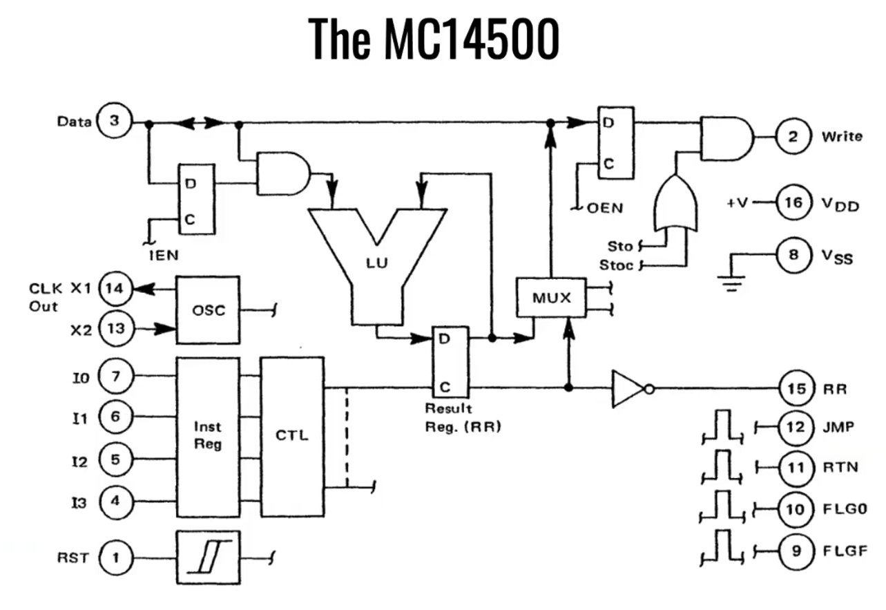
Nicola Cimmino used to frequent a facility that used to recycle electronic waste, which sold old bits and pieces of hardware by the kilo. Many times, Nicola would pick up odd boards with an eye to repurposing components for future projects. Eventually, one unremarkable looking chip caught his attention—the Motorola MC14500B. This chip was rather unique, being a rather simple processor with just 16 instructions and a 1-bit data bus.
The simple architecture of Motorola’s basic 1-bit chip. Credit: talk slides
It’s worth examining the era in which this chip existed. Intel dropped the 4-bit 4004 in 1971, with the famous 8-bit 8080 landing in 1974. The Zilog Z80 came along in 1976, similarly an 8-bit design. And yet, when Motorola released the MC14500 in 1977, it landed with a rather slimline 1-bit design instead. Nicola notes that this likely came down to price, since populating a chip with more transistors cost more money quite significantly back in the 1970s. If the job could be done with less, it would make the part cheaper and thus more popular in the market. Bearing this out, Nicola explains that a 1976 Zilog Z80 used 8,500 transistors and cost around $200 USD, while an MC14500 used just 500 transistors and could be had in 1977 for the bargain price of just $5 USD.
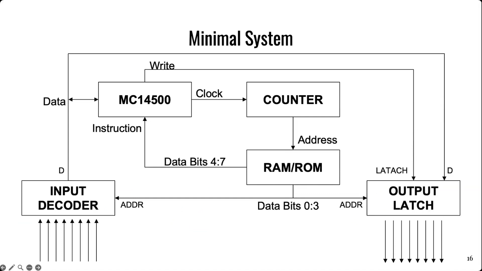
It doesn’t take much supporting hardware to get an MC14500 up and running. Notably, though, there is no memory or program counter on board, so those have to be added externally. Credit: talk slides
Back in the mid-1970s, automation in industry often consisted of simple logic that was handled by cabinets full of relays. This took plenty of bulk, required hard-wiring everything, and also involved plenty of electromechanical parts that could wear out. Changing logic required manually rewiring things which could be fussy and tedious at the best of times. In those days, the Programmable Logic Controller was just coming into use, developed to be a reprogrammable system for industrial automation tasks that was more flexible and reconfigurable just by reprogramming it.
The MC14500 sprung up as a useful tool at this time, powering a great many programable industrial systems. It was designed to offer the bare minimum requirements for its application, while leaving extraneous hardware for designers to implement if and when it was needed. The architecture is simple enough for Nicola to explain with a single slide. The chip came with a 1-bit logic unit, operating with a result register, a 1-bit accumulator and the data bus. A minimal system could be lashed up with the MC14500, a counter, some external RAM or ROM (since none was onboard), and an input decoder and output latch of 8 bits each. This setup would only allow for doing combinational logic, since there is nowhere to store the current state of the system. However, hooking some outputs back to the inputs could allow for sequential logic, since it would allow for storing the current state of the system via those outputs. Nicola then steps through various other configurational changes to addressing and system architecture that could be made to optimize the MC14500 for use in different ways.
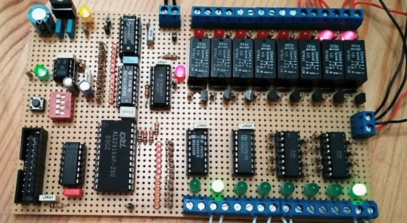
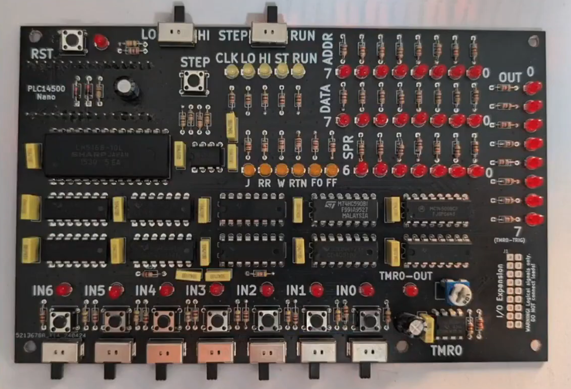
Nicola built a homebrew MC14500 system, allowing him to get to grips with the classic chip. Credit: talk slidesA more polished version came later, built on a custom PCB. Credit: talk slides
If you wanted to get to grips with using an MC14500 in industrial contexts, you would do well to pay attention to this talk, even if it came out some 40 years past the part’s heyday. Beyond the basic system architecture, Nicola explains how to use the limited instruction set, and how to get such a system executing simple programs in ladder logic, which remains somewhat of an industrial standard to this day. Beyond that, he steps up to more complex logic, like if/else conditionals and the use of some of the weirder instructions of the chip. He then shows off the hardware he built himself—both a breadboarded MC14500 setup built with wirewrap, and a more polished version on a custom PCB.
It’s not every day you get to learn about the nitty-gritty details of working with industrial hardware from the ground up. And yet, that’s exactly what Nicola brought to Hackaday Europe 2026. It’s an excellent primer on the topic, and also simply just good fun if you’re a fan of electronics and logic itself!
These days open source is everywhere, and frankly, we couldn’t be happier about it. But even with as prevalent as open software and hardware has become, we still occasionally hear about a project that takes the concept somewhere unexpected. Which is precisely why we were so eager to hear more about the fascinating work [Phil Underwood] has been doing.
In his talk Open Source Caving: 20 Years of Making Cave Mapping Tools at Hackaday Europe 2026, [Phil] takes us through a series of progressively more advanced open hardware devices that he’s designed to increase the speed and accuracy of underground mapping efforts. Along the way, he’s learned a number of valuable lessons about designing hardware that’s robust enough to handle the uniquely challenging environment underground while still being accessible enough for a hobbyist to build and use.
Improving on the Old School
It’s not much of a stretch to assume that most Hackaday readers haven’t spent a lot of time crawling through underground passages, and as such, may not be immediately aware of how one begins to map a cave in the first place. Helpfully [Phil] starts off his talk by explaining the traditional process — which generally involves a compass, an inclinometer, a tape measure, and plenty of intricate notes.
Once you’ve collected all that data and successfully returned to the surface with it, you can plug it into software and create a three dimensional map of the cave. Sprinkle in some surface topography, and you’ve got a pretty slick overview of whats above and below ground.
Like so many other cavers, [Phil] wanted a way to make that first half of the process a bit less tedious. He imagined an electronic device that could take at least some of the necessary measurements for him, but was limited by the technology and at-home production capabilities available to hobbyists in the early 2000s. There was also the cave environment to contend with: any piece of equipment used in a cave not only needs to be able to handle the dusty and cramped conditions, but must be reasonable shock resistant. If that wasn’t tricky enough, there’s also a non-zero chance that it will need to spend some amount of time underwater.
Incremental Improvements
The first-generation of [Phil]’s surveying device. Undaunted, [Phil] put his first electronic caving aid together in 2008. Inside the off-the-shelf Radio Shack enclosure was an 8-bit PIC18LF2550, a dot-matrix display, an accelerometer, and a magnetometer. The data from the two sensors could be used to determine the heading and angle that the device was being held at, and while it still required the operator to manually take a distance measurement along that vector, having two-thirds of the information already computed saved considerable time and effort during surveys.
The first-generation of [Phil]’s surveying device.The next big technological leap came in 2020 — not just in terms of the device itself, but in the tools [Phil] had access to. This new device utilized a 32-bit microcontroller, a 3D printed frame, and included a laser rangefinder.
Thanks to the the increased computational capabilities offered by the modern MCU, more of the necessary calculations could be done on the device itself, which further sped up the surveying process. But [Phil] notes that the data from the laser module wasn’t always reliable, and keeping the more complex device protected from the elements introduced new challenges.
Now evolving at a faster clip, by 2023 [Phil] had improved on the design with a better integrated 3D printed case, custom silicone buttons, and a more polished user interface. At this point, he also switched over to writing the device’s firmware in CircuitPython. The lower bar of entry compared to C seemed to better resonate with those in the community, and consequently [Phil] started seeing more code contributions from outsiders.
New Dimension, New Challenges
By this point [Phil] had a pretty solid handheld device to assist in performing cave surveys, but the end result was ultimately the same as if the measurements had been taken manually. Each successive generation of the hardware made the process of gathering spatial data faster and less cumbersome, but didn’t meaningfully improve the final product.
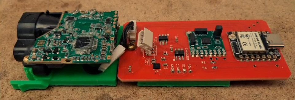
Creating higher fidelity maps would require more data and the computational power to churn through it, which is why the latest generation of [Phil]’s hardware utilizes a Raspberry Pi 5 Compute Module and a pair of low-light cameras to perform photogrammetry. When combined with the heading and angle data, this produces a textured 3D model of the inside of the cave with minimal manual effort on the part of the user.
While this latest generation of hardware is undeniably more capable than what came before it, there’s an argument to be made that it also takes a step backwards in some respects. The cameras represent a physical weak point, and [Phil] says he’s still working on an approach to more adequately handle the increased power requirements of the Pi 5 Compute Module compared to the microcontrollers used in his earlier devices. But just as with the rest of the problems faced over the last two decades, these issues will likely be resolved in time as well.
In the end, this incremental approach to hardware development may be the most valuable lesson to take away from [Phil Underwood]’s talk. It’s a safe bet that the vast majority of those who view this presentation will never find themselves exploring an underground cave system, much less mapping one. But that doesn’t mean they can’t learn from his practical and methodical approach to building the right tool for the job.

 Login
Login