Preparations for Next Moonwalk Simulations Underway (and Underwater)
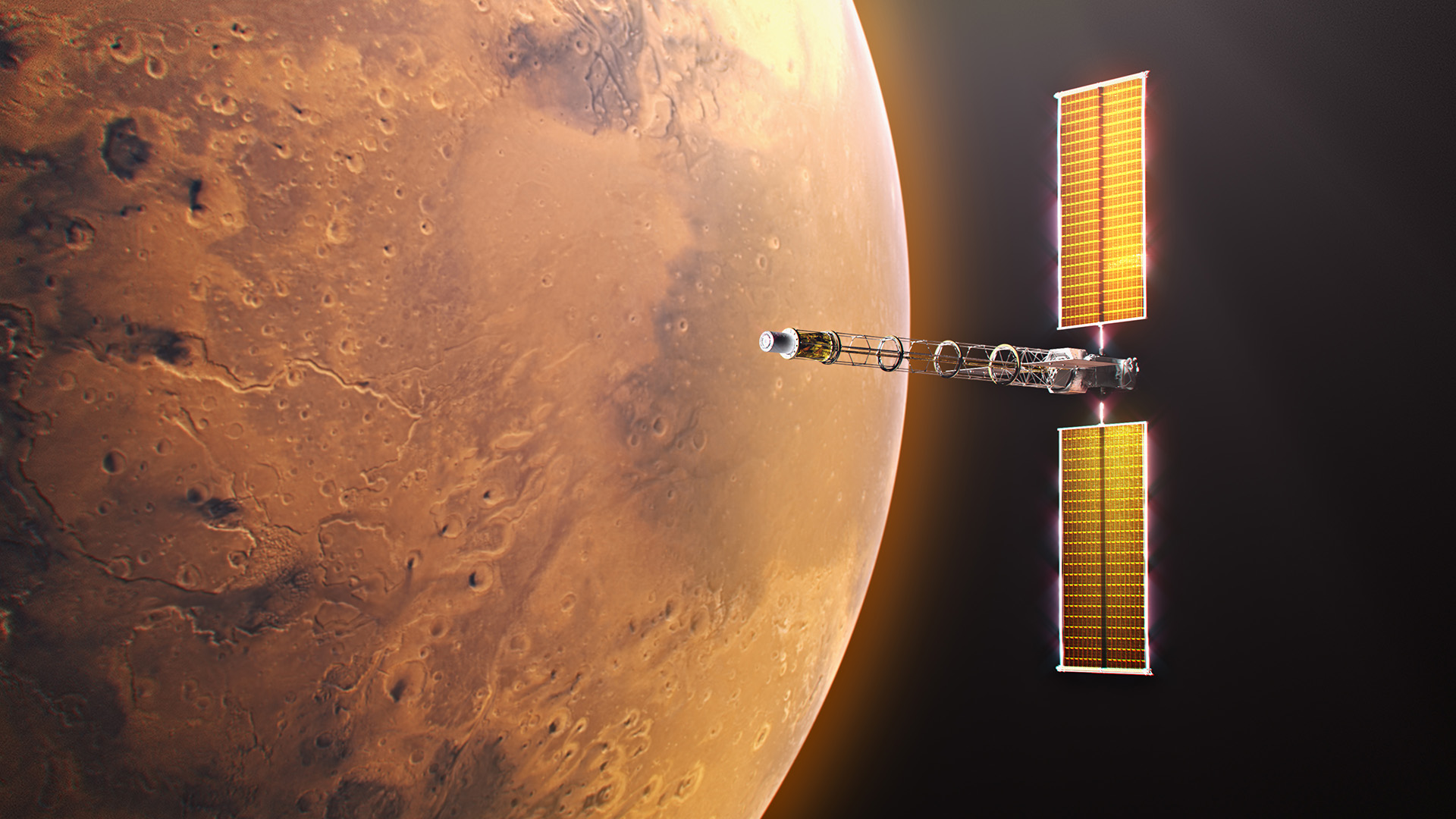
Space Reactor-1 Freedom will be the first spacecraft ever to demonstrate fission power beyond Earth’s orbit, traveling to Mars to deliver a science payload called SkyFall.
NASA/Alberto Bertolin
Destined for Mars and beyond, NASA’s Space Reactor-1 (SR-1) Freedom will be humanity’s first fission-powered spacecraft to travel outside Earth’s orbit. Announced during NASA’s “Ignition” event, this mission will demonstrate nuclear electric propulsion in deep space, and progress is underway on its key element: the nuclear power module. To expedite development of the spacecraft, NASA and its partners have mutually agreed to key contract actions that will advance the SR‑1 Freedom mission.
“These contract actions not only reduce technical risk and help us maintain momentum toward our 2028 launch, but they also strengthen collaboration across our partners,” said Steve Sinacore, SR-1 Freedom program director. “These actions keep SR‑1 Freedom on track and ensure we’re building the strongest possible foundation for NASA’s first fission‑powered voyage beyond Earth orbit while developing technology extensible to a vibrant space nuclear future.”
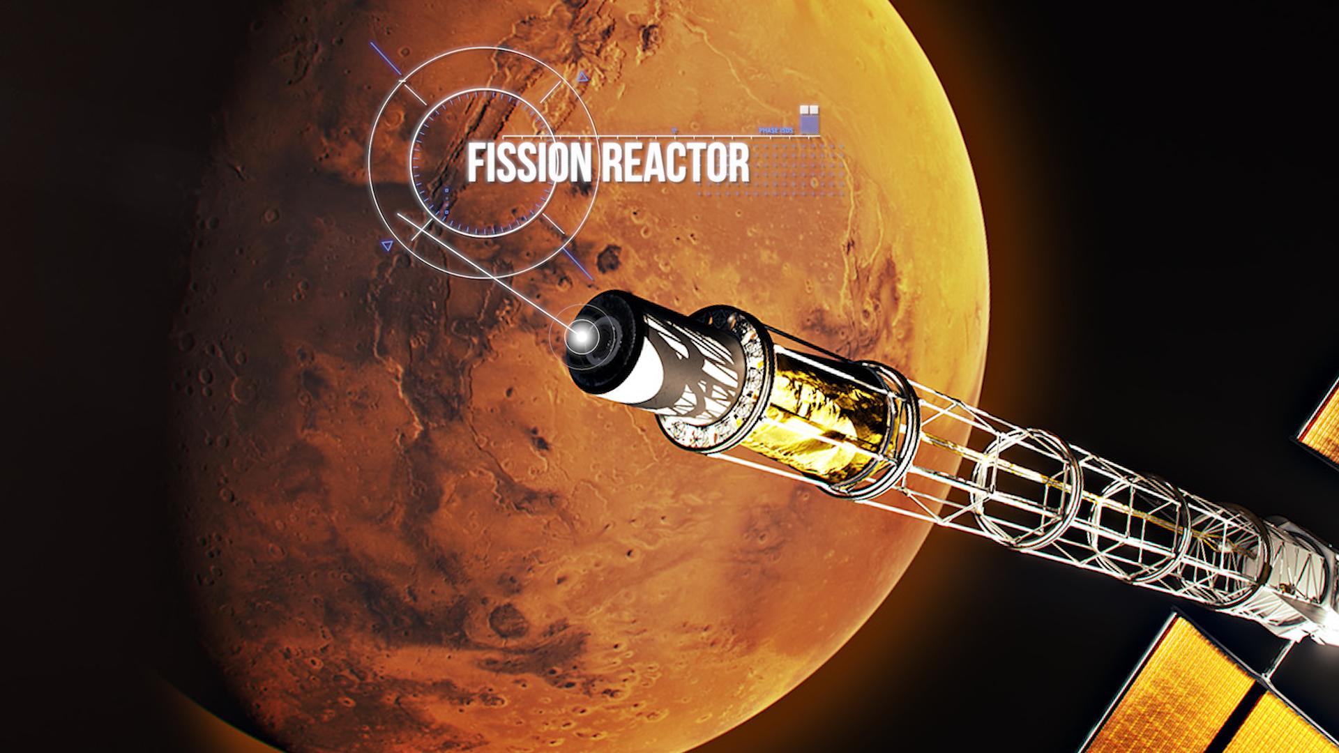
Space Reactor-1 Freedom’s nuclear power module, located at the end of the spacecraft’s boom, consists of a reactor that generates heat through nuclear fission and a power conversion system that converts that heat into electricity to power systems and electric propulsion.
NASA/Alberto Bertolin
Sierra Lobo Inc. will provide the nuclear power module’s closed Brayton cycle power conversion system, which converts thermal energy from its fission reactor into electrical power needed for SR-1 Freedom’s nuclear electric propulsion demonstration. The work will be conducted under the Space Flight Systems Development and Operations Contract III, awarded in 2024, to support spaceflight hardware design, development, testing, and operations at NASA’s Glenn Research Center in Cleveland.
The power conversion system will be integrated with the fission reactor, which is being designed and developed by the Department of Energy (DOE)’s Idaho National Laboratory to complete the nuclear power module. NASA and DOE incorporate thorough safety standards throughout the design and development of the SR-1 Freedom spacecraft, including interagency safety reviews, continuous oversight by a NASA chief safety officer, regulatory compliance, and a rigorous safety design process focusing on hazards, failure tolerance, and nuclear safety. In addition, the nuclear reactor portion of SR-1 Freedom will remain inactive until the spacecraft leaves Earth orbit.
Launching in late 2028, SR‑1 Freedom will deliver the SkyFall science mission, a team of three Mars helicopters evolved from the Ingenuity design, to collect scientific data, demonstrate exploration zones, and identify potential water sources. The mission will pave the way for deep space exploration and next‑generation fission-powered systems designed to keep NASA’s Moon Base operating through periods of darkness and in locations where solar power alone is not sufficient.
Preparations for Next Moonwalk Simulations Underway (and Underwater)
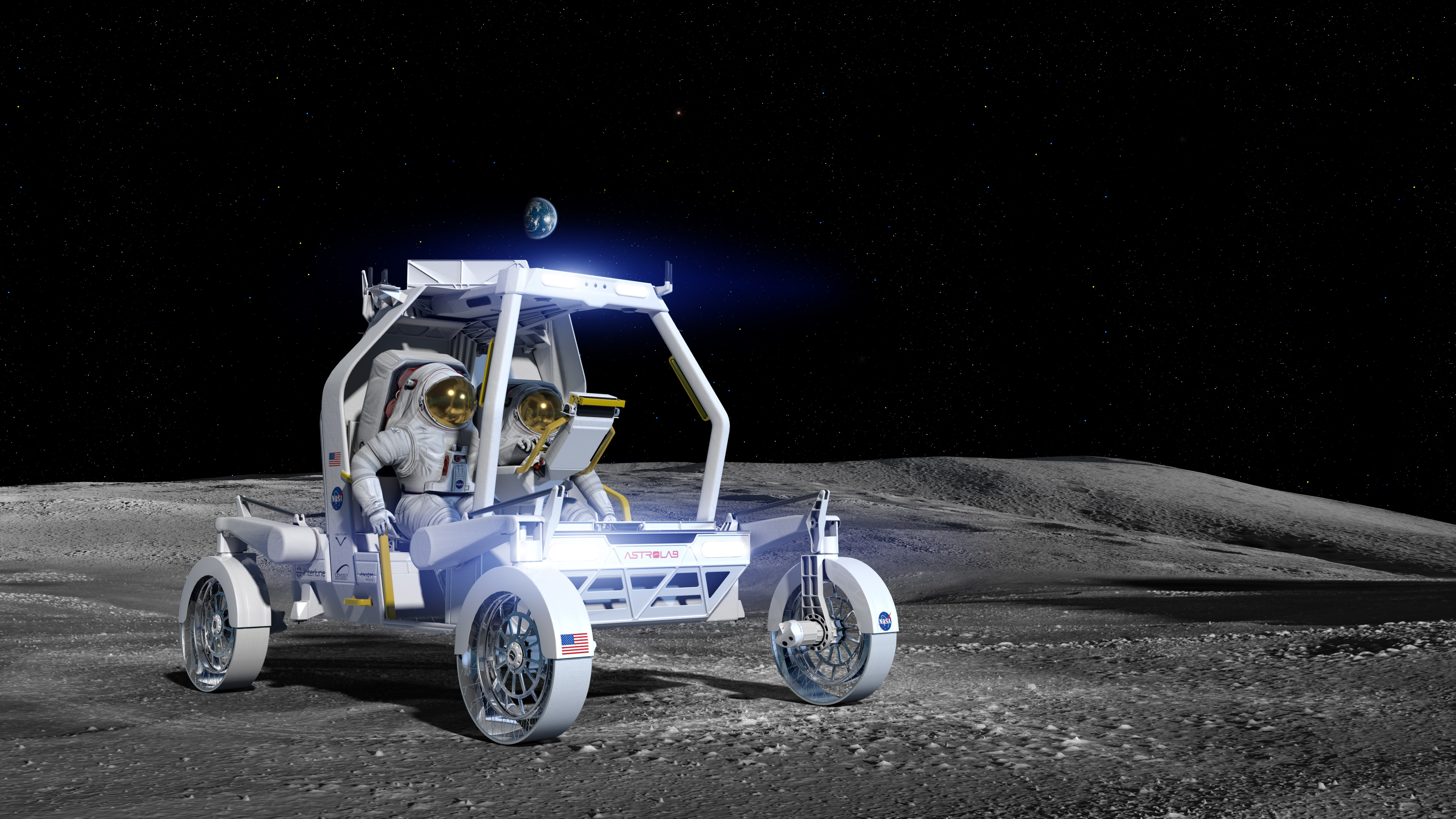
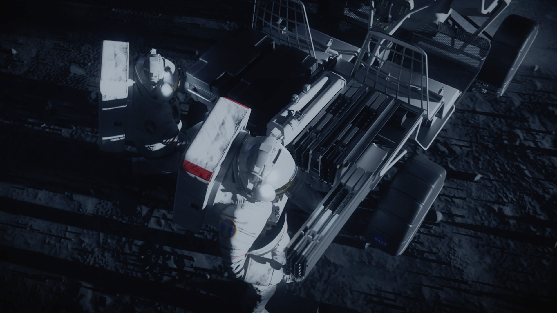
Artist’s rendering of astronauts working next to a lunar terrain vehicle on the lunar surface.
NASA
As NASA works to build the Moon Base, crewed and robotic lunar rovers will play a crucial role during early development through technology demonstrations, astronaut transport, terrain mapping, scientific investigations, and resource prospecting. Data from these early missions will inform future mobility systems and infrastructure needed for astronauts to live and work on the Moon.
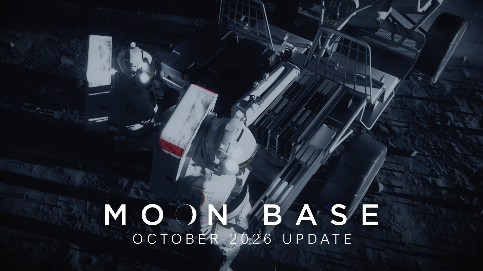
On Tuesday, NASA released a Moon Base video update offering a closer look at the progress being made on the commercial lunar terrain vehicles and robotic rovers that will enable the surface mobility needed to build humanity’s first lunar outpost.
“Lunar rovers are central to our surface mobility strategy,” said Robert Pickle, director of the Surface Mobility Office within the agency’s Moon Base Program. “Their performance will lay the groundwork for the mobility systems that will define the next era of exploration and ultimately determine how effectively we can build, operate, and expand the infrastructure required for long‑duration exploration.”
Learn more about NASA’s VIPER
An artist’s concept of NASA’s VIPER lunar rover on the surface of the Moon.
NASA/Daniel Rutter
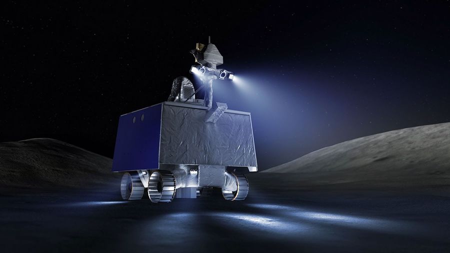
NASA’s VIPER (Volatiles Investigating Polar Exploration Rover) will embark on a mission to the lunar South Pole region in 2027 to venture into permanently shadowed craters looking for water and other valuable resources essential for sustainable exploration.
After delivery to the lunar surface by a Blue Moon Mark 1 lander, VIPER will travel more than 18 miles (30 kilometers), collecting information about the thermal, lighting, and terrain environment in the Moon’s South Pole region. This data could provide information about the origin and distribution of water on the Moon, help determine how lunar resources could be used for the Moon Base, as well as better understand the history of the Moon, Earth, and the processes that helped shape conditions for life.
Mission operations for VIPER will be run out of NASA’s Ames Research Center in Silicon Valley where teams are simulating possible scenarios for when the rover begins its mission on the Moon.
The VIPER rover is currently at NASA’s Johnson Space Center in Houston where it is fully built and undergoing final testing before traveling to NASA’s Kennedy Space Center in Florida for launch to the Moon.
Lunar terrain vehicles
To advance surface mobility on the Moon, NASA awarded Astrolab and Lunar Outpost task orders to build the first phase of Moon Base rovers capable of carrying crew, called lunar terrain vehicles (LTVs), that will be delivered to the Moon ahead of crewed Artemis missions. NASA awarded Blue Origin a task order to deliver the LTVs to the lunar South Pole region by 2028 through the agency’s CLPS (Commercial Lunar Payload Services) initiative.
The LTVs will be remotely operated from Earth, traversing up to 3.7 miles (6 kilometers) a day, mapping the lunar surface to help scientists produce high-resolution maps of the region, prior to crew arriving on future missions. The rovers also will collect information to help NASA and its partners learn about operating in this extreme environment, such as data on lighting, navigation, and how well the LTVs preserve energy and function when driving in and out of permanently shadowed regions that can reach minus 334°F (minus 203°C). This will help inform Moon Base development and improve on design and capability for future mobility systems, hardware, and infrastructure.
During missions on the lunar surface, Artemis astronauts will drive the LTVs as they explore geologically diverse areas of the lunar South Pole region, gathering geology samples to bring back to Earth for scientists to study. The LTVs will be able to support up to three moonwalks per Artemis mission, transport up to 176 pounds (80 kilograms) of lunar samples and tools, and travel up to six miles (10 kilometers) on a single battery charge.
Astrolab
An artist’s concept of Astrolab’s Crewed Lunar Vehicle, or CLV-1, on the surface of the Moon.
Astrolab
Astrolab’s Crewed Lunar Vehicle 1, or CLV-1, is a rover adapted from the company’s FLEX (Flexible Logistics and Exploration Vehicle) LTV architecture. Astrolab recently delivered a mockup of CLV-1 to Axiom Space, where NASA astronauts wore mock-ups of the Artemis lunar spacesuit and evaluated the lunar rover’s design, crew cabin, and display interfaces.
Prior to CLV-1 arriving to the Moon, Astrolab will send its first robotic rover, FLIP (FLEX Lunar Innovation Platform), to the lunar surface as a payload on Voyager Technologies’ Griffin Mission One scheduled to launch in late 2026. FLIP will study the environment of the South Pole and serve as a testbed for critical subsystems on CLV-1, which will include similar tires, batteries, radios, and cameras.
In the next few weeks, Astrolab engineers will head to NASA’s Glenn Research Center in Cleveland where they will use the center’s Simulated Lunar Operations laboratory to evaluate the how CLV-1’s flexible, airless wheels perform while driving on a simulated lunar surface.
Lunar Outpost
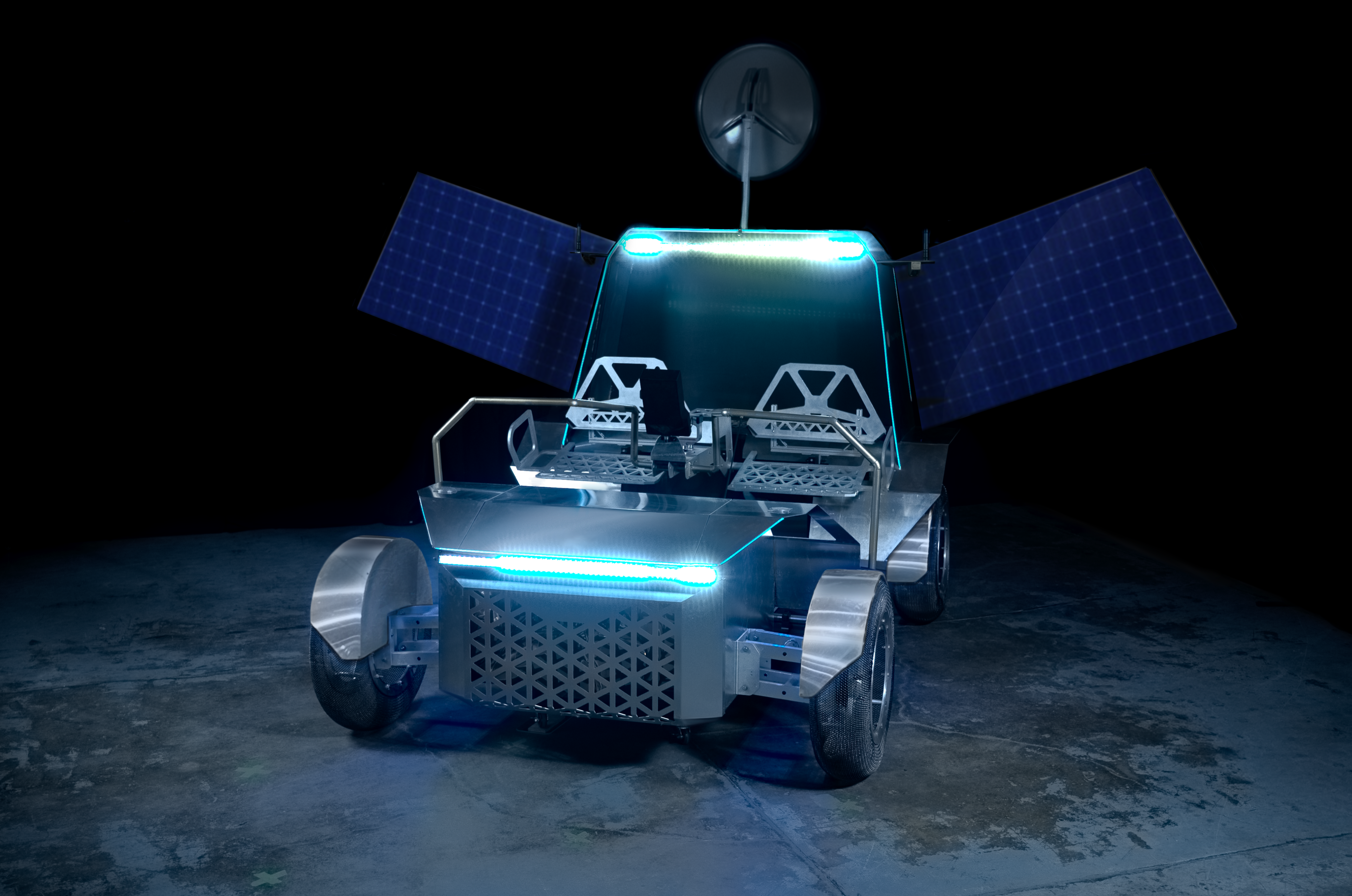
A full-scale prototype of Lunar Outpost’s Pegasus lunar terrain vehicle.
Lunar Outpost
Lunar Outpost’s Pegasus crewed LTV is a lighter, mission-ready evolution of the company’s Eagle LTV. Prior to the award, Lunar Outpost built two mockups of Pegasus and recently delivered a third static mockup to NASA’s Johnson Space Center for crewed testing. During the test, NASA astronauts wore pressurized spacesuits and evaluated the rover’s design, usability, and crew comfort.
In 2025, Lunar Outpost’s robotic exploration rover MAPP (Mobile Autonomous Prospecting Platform) operated at the Moon’s South Pole. During the mission, MAPP acted as a testbed and collected data, achieving flight-proven readiness for key hardware and software subsystems, like its automatic thermal control system, navigation cameras, and mission control software that will be used to remotely operate Pegasus. With a second MAPP rover scheduled to launch in early 2027, Lunar Outpost is advancing many of the key technologies that are directly transferable to Pegasus.
In the next few weeks, Lunar Outpost teams also will head to NASA Glenn to test and evaluate the soil mechanics, traction, and mobility of Pegasus’ spring mesh tires.
In the coming months, both Astrolab and Lunar Outpost will test drivable LTV mockups with NASA crew to evaluate how the rovers drive and operate in a simulated lunar environment. Lunar Outpost is scheduled to complete the preliminary design review of their LTV in October, and Astrolab is scheduled to complete their preliminary design review by the end of December. Both companies are on schedule to deliver the flight-ready hardware to NASA at the end of 2027.
As part of a Golden Age of innovation and exploration, NASA will send Artemis astronauts on increasingly difficult missions near the lunar South Pole to explore more of the Moon than ever before. In addition to providing economic benefits and advancing scientific discovery through its Moon missions, NASA will establish an enduring human presence on the lunar surface and build on the agency’s foundation for the first crewed mission to Mars.
There's a lot of ground to cover when you're building a Moon Base. From robotic rovers exploring the rugged lunar landscape to lunar terrain vehicles carryin...
Preparations for Next Moonwalk Simulations Underway (and Underwater)
Research teams at NASA’s Glenn Research Center are involved in developing theory and software to predict the noise from aircraft engines. This software helps engineers to design and analyze new and improved aircraft propulsion systems. Copies of our software can be requested from NASA’s Software Catalog.
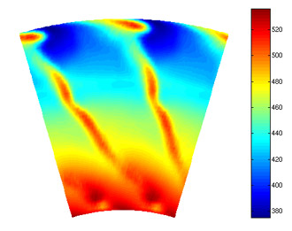
Aerodynamic predictions of a the hot exhaust flow through a dual stream nozzle with chevrons.
NASA
JeNo
Development of jet noise prediction codes is multifaceted. Since JeNo predicts jet noise using Lilley’s Acoustic Analogy and the mean flow solutions from a Reynolds-Averaged Navier-Stokes (RANS) code, accurate acoustic predictions hinge on accurate aerodynamic predictions. This is why acoustic source modeling and turbulence modeling, together with the development of advanced measurement systems, are the leading areas of research in jet noise prediction at NASA Glenn. RANS-based jet noise prediction schemes based on Lilley’s Acoustic Analogy offer relatively quick answers compared to those from alternative methods like Large-Eddy Simulations (LES) or Direct Numerical Simulation (DNS).
The JeNo jet noise prediction code calculates the far-field sound spectral density produced by axisymmetric jets at a user-specified observer location and frequency range. Currently, JeNo has been validated for subsonic and low supersonic, unheated axisymmetric jets. Copies of the JeNo code can be requested from NASA’s Software Catalog.
MGBK
Development of the MGBK code preceeded JeNo. Researchers at NASA GRC have used MGBK to predict trends in jet noise for complicated aircraft engine exhaust nozzles. MGBK was used to analyze the noise reduction benefits of chevrons–serrations on teh edge of turbofan nozzles–which are a familiar site on many commercial aircraft engines today. Copies of the MGBK codes can be requested from NASA’s Software Catalog.
V072
Predicated on simplistic models of the fan flow and geometry, V072 has been proven useful in studying rotor/stator interaction tone noise. When you need to design a low-noise fan stage, tone noise level predictions from V072 can help you make smart choices for such important design parameters as blade and vane counts, rotor-stator spacing, and stator vane sweep and lean. When you’re after quick noise estimates early in the design cycle, V072 may be your tool of choice. Copies of V072 can be requested from NASA’s Software Catalog.
TFaNS
Taking rotor/stator interaction noise prediction to the next level, not only can TFaNS calculate the tone noise levels generated by rotor/stator interaction it can also account for the blade row acoustic coupling effects such transmission and reflection and can propagate those tones to the far field. Like V072, TFaNS runs quickly and can be used in early design stages for studying trends. Copies of TFaNS can be requested from NASA’s Software Catalog
Linflux
When simple models are too simple, an analysis with Linflux gives you the power to study realistic, 3-D flows and blade geometries. Compared with V072 and TFaNS, Linflux requires significantly more computational resources since it models much more of the physics involved. Linflux predicts rotor/stator tone noise and, like all the software developed by the NASA Glenn Acoustics Branch, has been rigorously validated against experimental data. Copies of Linflux can be requested from NASA’s Software Catalog.
BFANS
Using estimates of turbulence intensity and characteristic length scale as input, BFANS can be used to calculate the broadband noise generated by turbulence impinging on the leading edges of the rotor blades and stator vanes. Calculations with BFANS, combined with experimental data from tests at facilities like NASA Glenn’s 9’x 15’ Low Speed Wind Tunnel, can be used to hunt down the noisiest components in a fan stage. Copies of BFANS can be requested from NASA’s Software Catalog.
RSI
RSI is a computer code for calculating the spectrum of broadband noise produced as a result of the interaction of the fan rotor wake turbulence with the fan exit guide vanes. The software computes the spectra of acoustic power upstream and downstream of the stator on a mode-by-mode basis at each frequency of interest given information about the incident turbulence characteristics. The target frequencies are arbitary and need not be harmonics of the blade passing frequency of the fan. Copies of RSI can be requested from NASA’s Software Catalog.
WOBBLE
Propeller noise can be strongly affected by any inflow that leads to unsteady blade loading. The WOBBLE code computes the tone noise associated with propellers with varying inflow angle and predicts the axial and circumferential directivity. Inflow angle is specified in terms of yaw, pitch, and roll angles of the aircraft. The acoustic model is exact and accounts for all unsteady sources such as thickness and loading effects from the blades. Copies of WOBBLE can be requested from NASA’s Software Catalog.
MPT
Multiple pure tone noise (aka “buzz saw” noise), created by rotor locked shocks present when the fan blade tip speed is supersonic, can be estimated with the MPT code. The MPT codes also use flow predictions from a Computational Fluid Dynamics (CFD) code as input. This tool can be used by engineers to study the real-world effects of blade-to-blade difference caused during fabrication (manufacturing variations) or during hot-running operation (blade setting angle and untwist variations). Copies of the MPT code can be requested from NASA’s Software Catalog.
ADPAC
Developed by the Allison Engine Company under contracts with Glenn Research Center, ADPAC solves tightly coupled internal/external flows through future-concept short-duct turbofan engines. ADPAC is one of our flexible validated CFD tools. Characteristics of the problems that can be modeled with ADPAC include: 2D/axisymmetric/3D/mixed, steady/unsteady, inviscid/viscous, rotating/non-rotating/mixed components, with bleeds, leakages, and injection. ADPAC was developed specifically for propulsion system aerodynamic analysis Copies of the ADPAC code can be requested from NASA’s Software Catalog.
Contact Us
Need to reach us for more information about our research, software, or data? Get in touch via the link below.
Preparations for Next Moonwalk Simulations Underway (and Underwater)
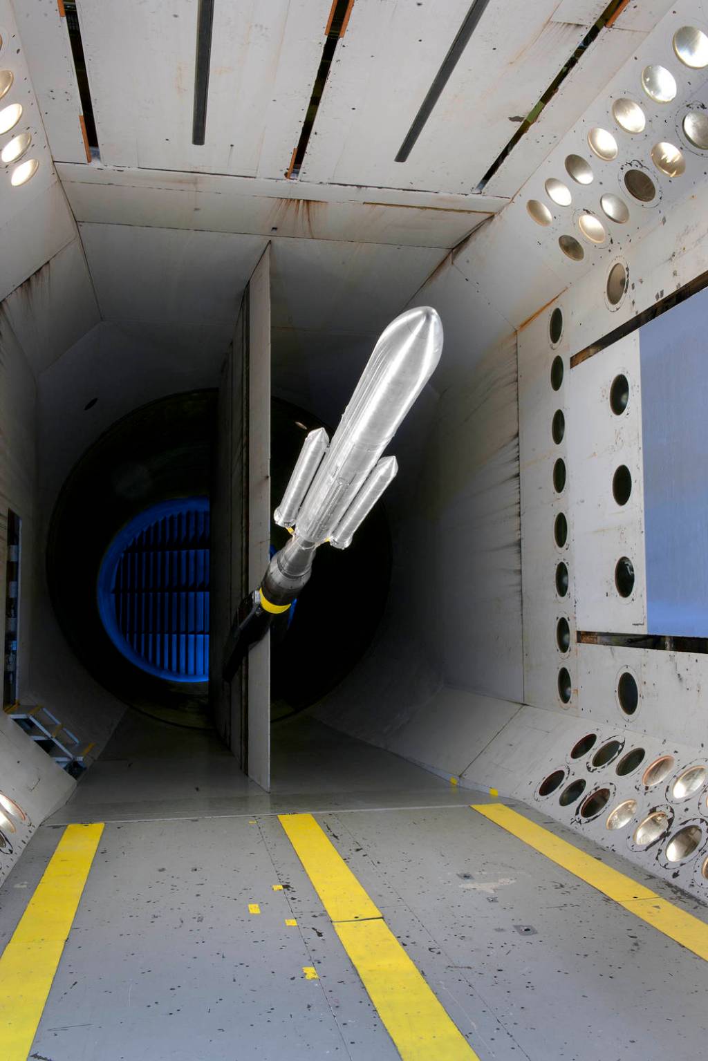
Research teams at the NASA Glenn Research Center perform experiments in world-class facilities such as the 9- by 15-Foot Low-Speed Wind Tunnel (9 x15 LSWT), the Aero-Acoustic Propulsion Laboratory (AAPL), the Small Hot Jet Acoustic Rig (SHJAR), the Nozzle Acoustic Test Rig (NATR), the DGEN AeroPropulsion Research Turbofan (DART), and the Acoustical Testing Laboratory (ATL).
9×15 Low-Speed Wind Tunnel (9×15 LSWT)
The 9- by 15-Foot Low Speed Wind Tunnel is specially designed to give researchers a controlled environment to study aircraft engine aerodynamics and acoustics at takeoff and landing conditions. This helps us to reduce noise in communities near airports. Major modifications were completed in 2019 to improve the flow and lower the background noise of the tunnel. A new 5-sensor traversing microphone rake helps measure sound produced by scale experimental propulsors. Read more about the capabilities of the 9 x 15 LSWT on our facilities page.
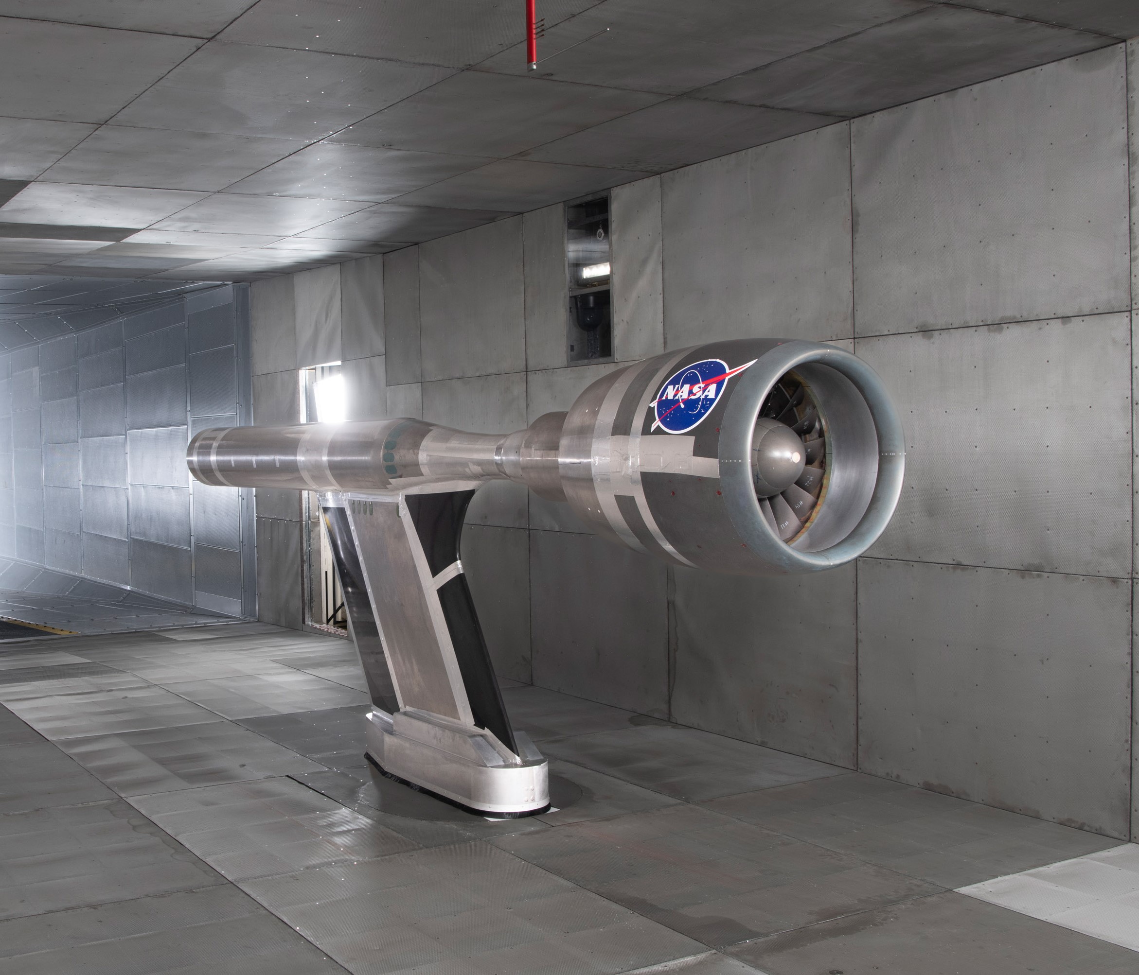
Advanced Ducted Propulsor (ADP) Fan Commissioning Test (side view) in the 9×15 Low-Speed Wind Tunnel.
NASA
Aero-Acoustic Propulsion Laboratory (AAPL)
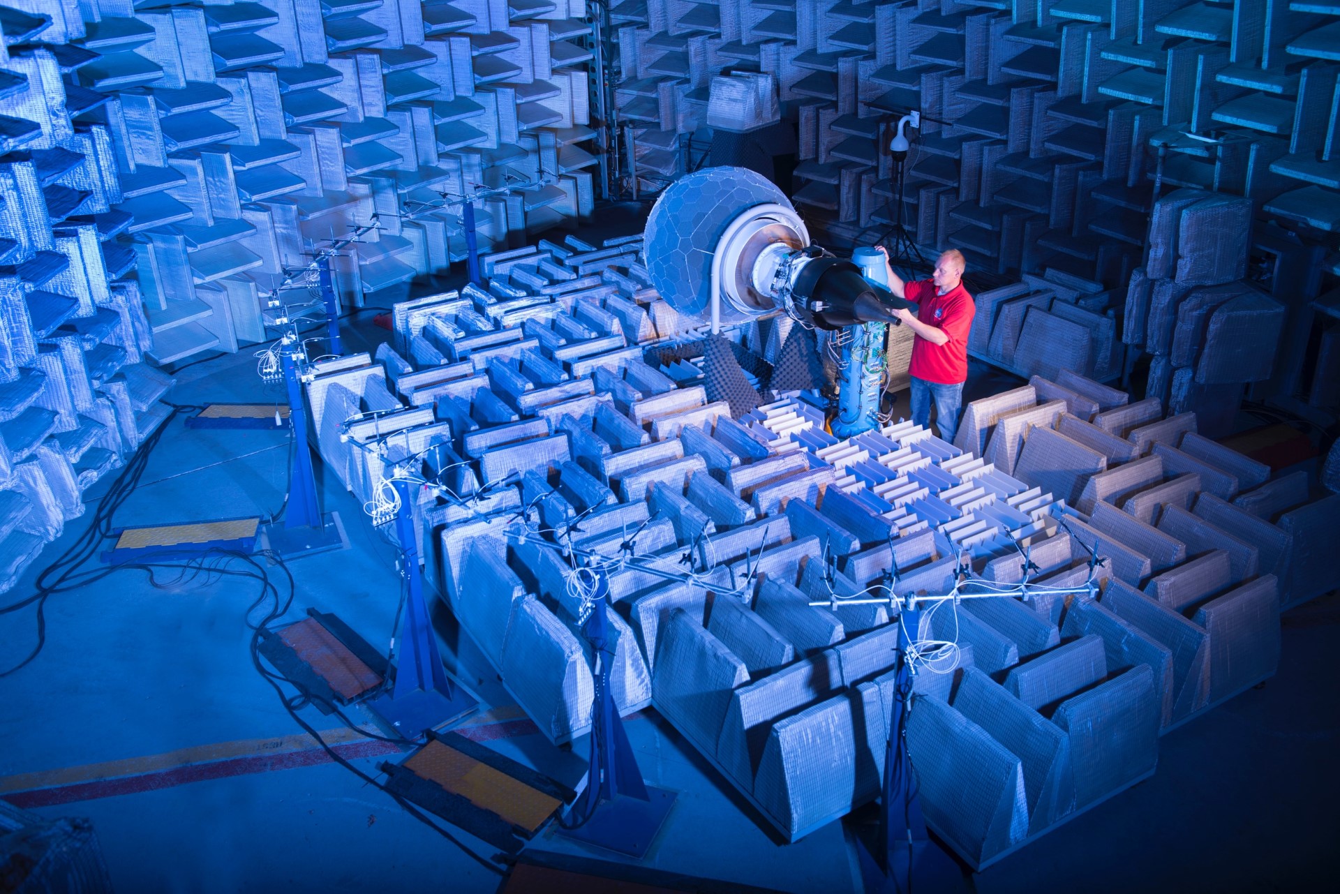
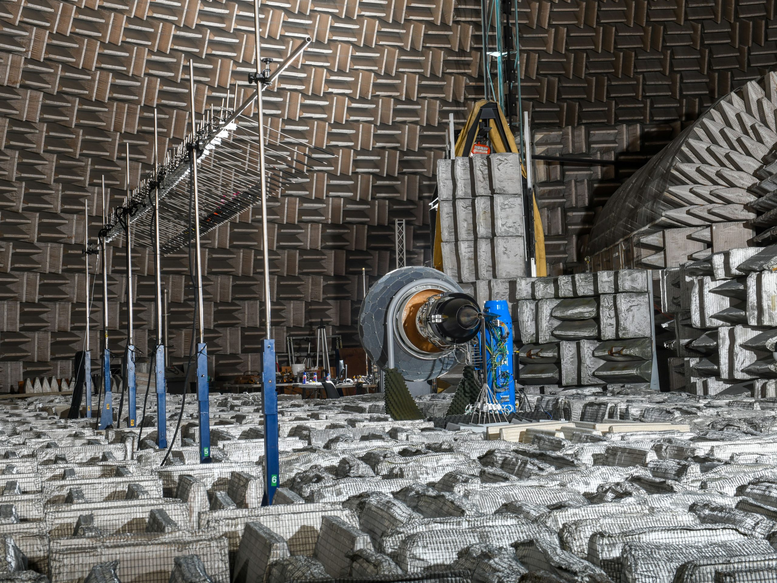
The Aero-Acoustic Propulsion Laboratory (AAPL) is a dual-purpose 65-foot radius geodesic dome used to reduce community noise and perform aeroacoustic tests of aircraft engines and engine components. The test area inside the dome can be configured as a hemi-anechoic or anechoic chamber. There are no echoes in the dome during tests because 17,000 custom-designed 2-ft thick fiberglass wedges are mounted to the inside surface of the dome walls and placed on the floor and around test rigs to absorb sound and prevent sound reflections. When AAPL was constructed in 1993, it was the first known free-standing geodesic dome to include materials to reduce transmission of sound through the walls and absorb sound within it. AAPL currently houses the Nozzle Acoustic Test Rig (NATR), Small Hot Jet Acoustic Rig (SHJAR), and the DGEN 380 Aeropropulsion Research Turbofan (DART). Read more about the capabilities of the AAPL on our facilities page.
The Aero-Acoustic Propulsion Laboratory at The NASA Glenn Research Center in Cleveland is an anechoic chamber used to measure noise from experimental aircraft engines such as the DGEN 380 Aeropropulsion Research Turbofan (DART) shown here.
NASA/Bridget Caswell
Small Hot Jet Acoustic Rig (SHJAR)
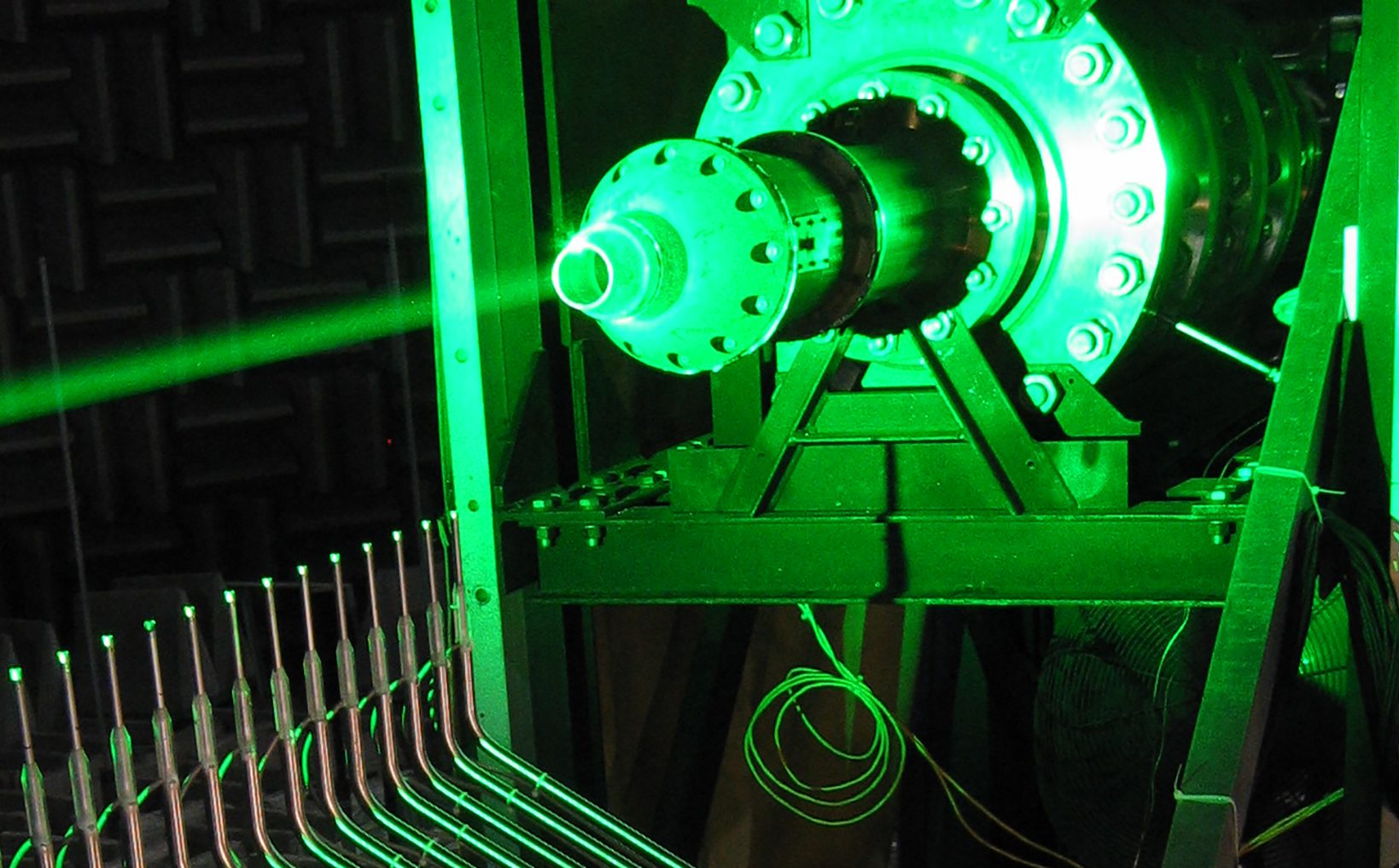
SHJAR is one of three rigs installed inside the anechoic dome of the Aeroacoustic Propulsion Lab. It can be used to test single stream nozzles up to 5 cm in diameter, Mach 2.0 and 800 K. SHJAR is a key tool in connecting the dots between nozzle geometry, jet flow, and noise. Creative nozzle designs are inexpensively created for this rig, and their impact on flow and noise is measured with world-leading measurement techniques. Researchers at NASA Glenn have been using SHJAR to develop advanced flow measurement techniques like Rayleigh Scattering, Raman Scattering, digital Schleiren, and real-time Particle Image Velocimetry. Three-dimensional microphone arrays have been deployed to map the sources of the noise. These techniques hold the promise of unlocking some of the mysteries of how the turbulence caused by the nozzle creates noise. The data from this rig is used to validate the computer codes that are being developed to calculate jet noise. Better noise prediction codes will help engineers design quieter nozzles.
Among the many firsts in turbulent jet research produced on SHJAR, time-resolved measurements of turbulent temperature were recently made using Raman-based optical methods, achieving high-frequency measurements of thermodynamic temperature fluctuations needed to complete turbulence models used in heat transfer as well as jet noise. In 2006, researchers had used the first time-resolved particle image velocimetry to measured space-time correlations of turbulent velocities in hot jets, a flow statistic key to the production of noise. Time-resolved velocimetry was also used to map convection speeds of turbulence, another flow metric required by jet noise theory but previously unavailable in hot jets.
The SHJAR is not only a good place to develop advanced diagnostic techniques, it has been a good testbed for exploring canonical problems in jet noise such as how the installation of the jet on an aircraft changes the noise produced by the jet. Jet-surface interaction, where the plume of the jet interacts with the wings, flaps, and tail of an aircraft, was identified as a fundamentally different noise mechanism in SHJAR tests.
Most of these ground-breaking measurement techniques and practical noise insights first developed on the relatively simple SHJAR have been deployed on the high-fidelity Nozzle Acoustic Test Rig (NATR), co-located in the Aero-Acoustic Propulsion Lab. Read more about the capabilities of the SHJAR on our facilities page.
Simultaneous measurements of turbulent flow and near-field acoustics in the Small Hot Jet Acoustic Rig (SHJAR)
NASA
Nozzle Acoustic Test Rig (NATR)
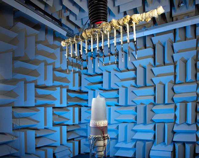
The Nozzle Acoustic Test Rig (NATR), a free-jet wind tunnel, plays a key role in evaluating jet noise reduction concepts so that only the most promising concepts are selected for full-scale engine tests. Scale models of nozzles from both military and commercial aircraft engines can be tested in the NATR, which is one of three test rigs housed in the NASA Glenn Aero-Acoustic Propulsion Lab. The NATR can simulate take-off and landing flight conditions up to Mach 0.35. A jet engine simulator with up to three streams of air at a variety of pressures and temperatures simulate the flow of a turbofan engine to evaluate advanced nozzle concepts. The arc of microphones overhead simultaneously measures the far-field noise at all angles, allowing accurate translation of measurements to those of an actual aircraft flying overhead. The NATR enables engineers to evaluate a number of nozzle noise reduction concepts at a fraction of the cost and time required for a full-scale engine test.
Over its 30-year history, NATR has been the origin of many important jet noise breakthroughs. First built to support jet noise testing for the High-Speed Research program on commercial supersonic airliners, the facility has hosted many test programs led by NASA and industry. The chevron nozzles seen flying on today’s aircraft were first ‘discovered’ during a NASA-led test campaign in 1997. Over the years industry has used the rig to develop noise prediction methods for near-term designs. NASA has explored low-noise concepts for engines that are not yet available, such as engines with dual-fan systems. Recent tests have measured the noise likely to be heard from supersonic airliners, reducing the risk that these unique aircraft will not be allowed to fly from current airports. The tests also point to technologies to reduce their noise, allowing the aircraft designers to make the aircraft more efficient and environmentally acceptable.
The ability to test nozzle with flight is critical, as this has a strong impact on the noise produced by the relative velocity of the jet and the surrounding air, and it is a key feature allowing noise measurements to be directly transformed to what would be heard from a real airplane flying overhead. The large size of the anechoic space around the NATR is also critical to measuring the true acoustic far-field of the jet nozzle. The NATR in the Aero-Acoustic Propulsion Lab is one of the very few facilities in the world where these measurements are possible, and the only facility where both flow diagnostics and acoustics can be made on the same rig, a key capability in understanding the relationship between jet flow and noise. Read more about the capabilities of the NATR on our facilities page.
Harware photographs of Lear Jet Nozzle Test 2018 in the Aero-Acoustic Propulsion Laboratory AAPL, Nozzle Acoustic Test Rig, NATR
NASA/ Rami Daud
DGEN AeroPropulsion Research Turbofan (DART)
DGEN 380 is the primary component integrated into the NASA Glenn Research Center’s DGEN Aero-propulsion Research Turbofan (DART). It serves as a flexible, relevant, experimental aeroacoustic and aero-performance test bed, providing valuable information throughout NASA’s technology maturation process for a variety of multidisciplinary research that includes turbofan noise, engine controls, installation effects, and measurement technologies.
Recent tests were completed August 2019 to develop a better understanding of propulsion-noise sources to enable improved turbofan noise-prediction methods and noise-mitigation techniques. Simultaneous acoustic measurements were obtained using a circumferential infinite-tube-probe array at the core-nozzle exit in conjunction with sideline and farfield microphone arrays. The extensive data set will allow for the application of advanced source-separation and phased-array methods to elucidate not only the core-noise structure, but also the propagation characteristics of other propulsion noise sources. Read more about the capabilities of the DART on our facilities page.
DGEN 380 AeroPropulsion Research Turbofan (DART) in the Aero-Acoustic Propulsion Laboratory.
NASA
Acoustical Testing Laboratory
The Acoustical Testing Laboratory at NASA GRC is used to support NASA’s human space exploration and aeronautics research missions. The ATL is a versatile test chamber that can be configured as an anechoic or hemi-anechoic chamber. Dense rubber material in the walls and ceiling of the ATL absorb or reflect sound from the outside. 34-inch deep fiberglass wedges that line the walls and floor are designed to absorb 99% of incident sound above 100 Hz which helps create an ideal environment for making acoustic measurements. A separate control room is attached for any noisy equipment or persons needed to perform the measurements.
The ATL has been used to quantify the noise emissions of experiments performed on the International Space Station, to measure noise sources and levels from electric motors, to calibrate microphone equipment, to measure the effectiveness of acoustic liners for aircraft engine models and to evaluate the over-the-wing engine placement for reducing takeoff and landing noise. Recent tests in the ATL have also included a scale model of a supersonic aircraft engine inlet and a spacecraft cabin ventilation fan.
Preparations for Next Moonwalk Simulations Underway (and Underwater)
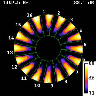
To measure airflow and sound, research teams at the NASA Glenn Research Center use special instrumentation like particle image velocimetry, hot wire anemometry, Raman spectroscopy, microphones in phased arrays or continuously rotating rakes. The global aviation noise reduction community relies on data from NASA GRC experiments to validate theory and noise prediction software.
Rotating Rake Mode Measurement System (RRMS)
Hear an annoying tone from your turbofan engine? Engineers might prescribe an advanced liner or specially tuned active noise control system to quiet it down.
To get it right, though, more information about the modal content of the tone is needed. This kind of data can’t be measured with a stationary microphone, which is why NASA Glenn engineers pioneered procedures using rotating microphones in the 1990s.
Rotating Microphone Rakes have been used by NASA Glenn researchers in a wide variety of tests ranging from low-speed proof of concept tests in the Advanced Noise Control Fan Rig and 9- by 15-Foot Low Noise Wind Tunnel to full-scale turbofan engine ground tests.
Rotating Rake Mode Measurement System (RRMS)
NASA
Microphone Phased Arrays
In a phased array system, microphones are placed in a 1D, 2D or 3D arrangement and when sound measurements from these microphones are properly processed, noise sources can be pinpointed.
NASA Glenn has an Array48 microphone system that has been used extensively to locate noise sources in scale-model jet flows, a counter-rotating open rotor fan model, and even a full-scale F404 military engine. Through NASA funding, a method has been developed to use microphones embedded in the fan duct of an engine to determine the location of noise sources on the rotating blades.
Phased Array Microphones determining the location of noise sources on the rotating blades.
NASA
Hotwire, Hotfilm, and Laser Doppler Velocimetry
We know that annoying tone noises can be created by periodic disturbances, such as when the wake from a fan blade interacts with a downstream stator vane. We also know that broadband noise is generated when an aircraft engine ingests turbulent air. Therefore, we must be able to record detailed velocity measurements of the air passing through an experimental propulsor so we can identifying noise sources and work to mitigate them. We must use special instrumentation like hotwire probes and Laser Doppler Velocimeters (LDV) to measure the air velocity upstream, downstream, and between the rotor and the stator of an experimental propulsor. Plots of the velocity measurements can be made which allow us to visualize the disturbances that the rotor created. Hotwire and LDV data are routinely used to validate calculations used to estimate noise from turbofan engines.
Hotwire, Hotfilm, and Laser Doppler Velocimetry
NASA
Contact Us
Need to reach us for more information about our research, software, or data? Get in touch via the link below.
Preparations for Next Moonwalk Simulations Underway (and Underwater)
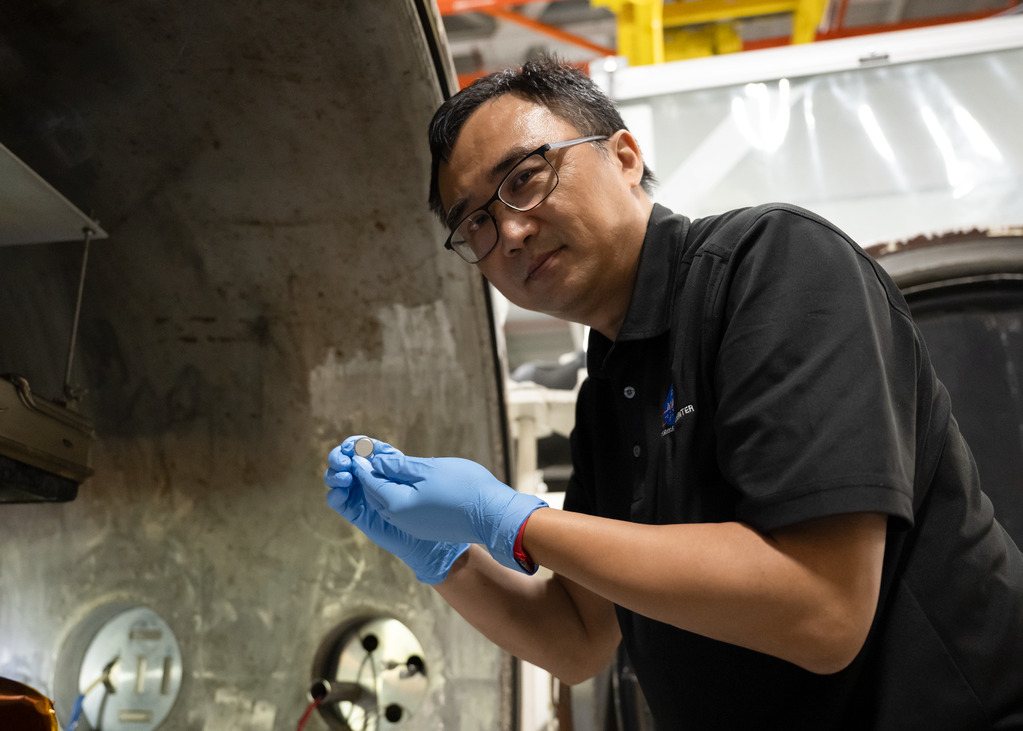
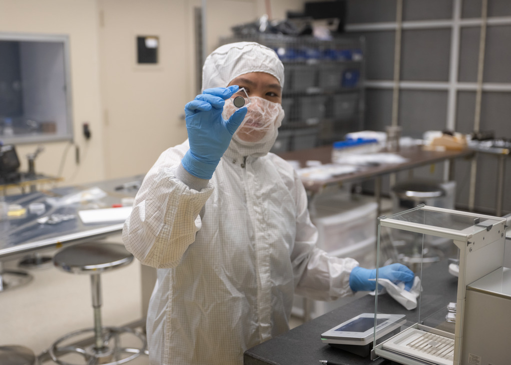
Yi Lin, SPEARS testing and research lead at NASA Langley, holds one of the small coin-cell batteries that had just undergone thermal vacuum testing.
NASA/Ryan Hill
If you’ve ever had your car start sluggishly, or not at all, on a particularly frigid winter morning, you know standard batteries do not like extreme cold. That’s why NASA researchers are working to develop a battery that could function in the brutal cold of the Moon’s South Pole, where nighttime temperatures plunge to minus 328 degrees Fahrenheit (minus 200 Celsius).
For future lunar operations, a battery will need to work immediately when warmed up and be able to power everything from an astronaut’s emergency kit to a rover capable of exploring the Moon’s darkest craters — all without posing a fire hazard.
A team of NASA researchers is working to make all that happen. The project is called Solid Power for Extreme Environment Adaptability and Resilience in Space (SPEARS), and it could provide NASA with an important tool to help power humanity’s sustained presence on the Moon through the Artemis campaign.
“Batteries have become an important part of our lives here on Earth, which enable our laptops, cell phones, power tools, and even our vehicles,” said Donald Dornbusch, principal investigator for SPEARS at NASA’s Glenn Research Center in Cleveland, where the project is led. “We will need them on the Moon, too, and these batteries will be required to operate reliably and safely in this harsh environment. That’s why we’re working on this technology.”
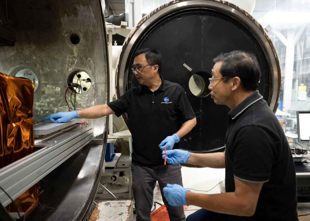
Yi Lin, left, SPEARS testing and research lead, and Ji Su, a polymer materials scientist and the task lead, during the removal of SPEARS batteries from thermal vacuum testing at NASA Langley.
NASA/Ryan Hill
Splashy problem, solid solution
Traditional lithium-ion batteries like those in your cell phone and laptop have a critical weakness: they rely on liquid electrolytes. Cool a conventional battery to the Moon’s nighttime temperatures, and that liquid would freeze, potentially damaging the battery. Heat it up too much — say, to daytime lunar temperatures of 212 F (100 C) — and it won’t work until cooled. Expose the liquid to the vacuum of space, and it evaporates.
SPEARS batteries solve these problems by replacing the liquid electrolyte with a solid ceramic- or polymer-based material. This change could unlock several advantages. First and foremost, they could operate in the heat and extreme cold.
During recent thermal vacuum testing at NASA’s Langley Research Center in Hampton, Virginia, small prototype battery cells operated well up to 176 F (80 C), down to minus 76 F (minus 60 C), and with slightly reduced performance down to minus 112 F (minus 80 C).
“We proved for the first time that these cells can work down to minus 80 degrees Celsius,” said Yi Lin, SPEARS testing and research lead at NASA Langley.
Lin also said he’s confident they can improve performance and maybe even expand that range in coming years.
The batteries need to remain reliable through exposure to the Moon’s wild temperature swings between day and night. The thermal vacuum testing showed that after exposure to temperature extremes from 212 F (100 C) to minus 274 F (minus 170 C), SPEARS batteries don’t sustain damage.
Just like the chemistry in your earbuds is different from the chemistry in your phone, which is different from the chemistry in your car, all these chemistries can still function with a solid electrolyte. We can tune for energy, tune for power, tune for durability, depending on the application.
Yi Lin
SPEARS testing and research lead
Not even solid-state batteries will function while they’re at a temperature as low as minus 274 F, but because solid electrolytes don’t freeze like a liquid, the batteries can survive the extreme low temperatures.
In order to get the batteries working again after exposure to such cold, small heaters come into play. SPEARS batteries wouldn’t need to be kept warm all the time, just warmed up to operational temperature. That could reduce the need for heavy thermal management systems in spacecraft and lunar habitats, allowing for lighter designs, lower costs, and longer mission durations.
Nike Lin, a support engineer/technician on the thermal vacuum team, takes weight measurements of batteries following thermal vacuum testing.
NASA/Ryan Hill
Power for Moon, Earth
The applications for these solid-state batteries are nearly limitless, from small tools like drills that must operate in shadowed lunar craters, to rovers and emergency power packs for astronauts. They also could provide power solutions for long-duration scientific instruments.
“We can tune the chemistry by using different electrode materials,” said Lin. “Just like the chemistry in your earbuds is different from the chemistry in your phone, which is different from the chemistry in your car, all these chemistries can still function with a solid electrolyte. We can tune for energy, tune for power, tune for durability, depending on the application.”
While SPEARS is designed for space, the technology could be spun off into Earth-based applications. In fact, SPEARS evolved out of a previous battery project Lin and Dornbusch worked on that focused on aeronautic applications.
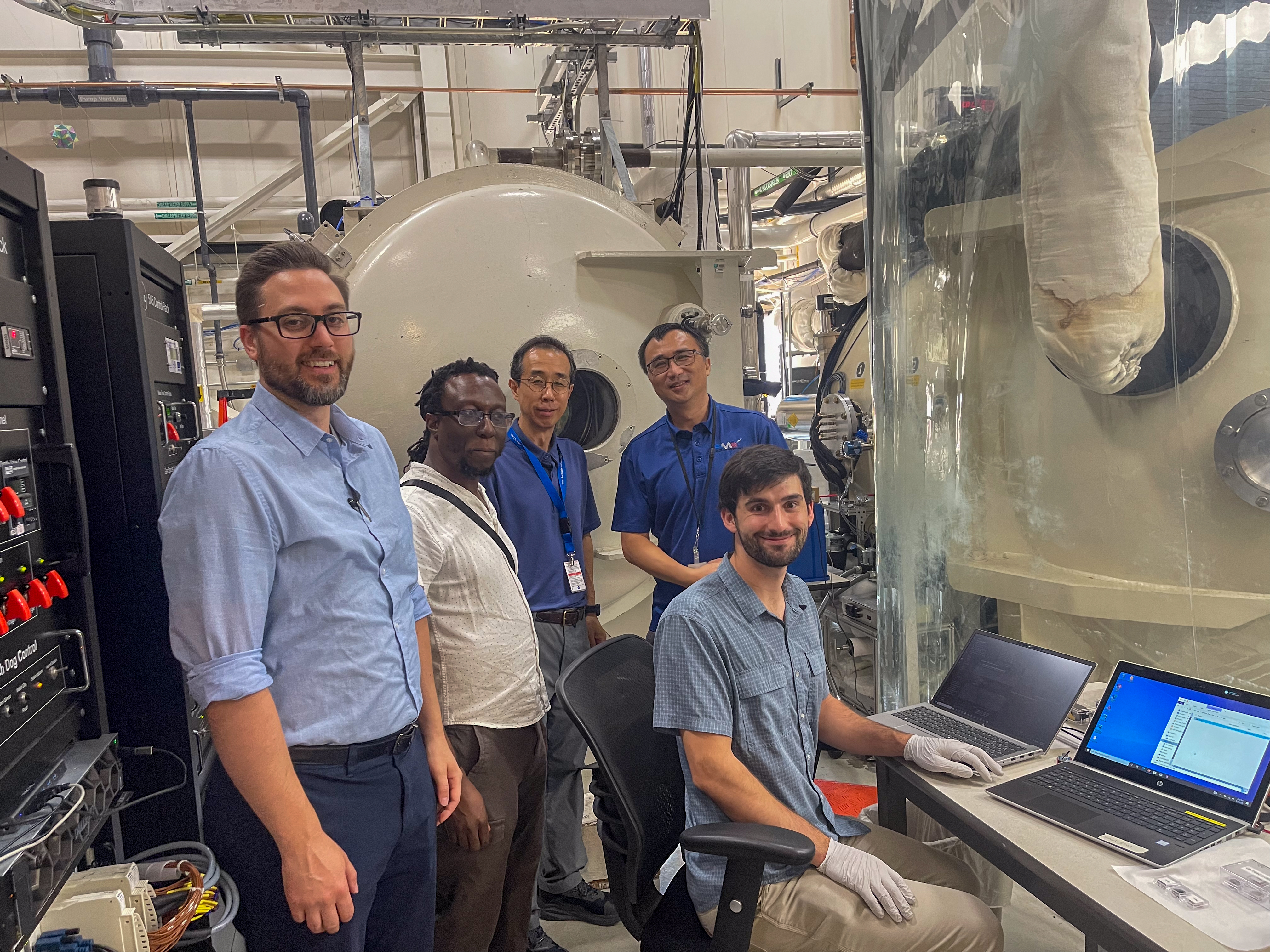
From left to right: Donald Dornbusch (NASA Glenn), Godfrey Sauti, Sang-Hyon Chu, Yi Lin (NASA Langley), and Malachi Mooney-Rivkin (NASA Ames), during a round of TVAC testing at NASA Langley.
NASA
“The potential market for solid-state batteries is very broad,” said Ji Su, a polymer materials scientist and the task lead at NASA Langley. “Automobiles, cell phones, communication devices, drones — anything that needs a portable power supply.”
The SPEARS project began in 2026 with funding through the Advanced Research and Technology division within the agency’s Research and Technology Mission Directorate. The project is set to focus on technology development in its first stages before potentially shifting toward commercial collaboration. NASA’s Ames Research Center in California’s Silicon Valley is working to develop flight hardware such as test boards and electronics to help prepare the SPEARS batteries for spaceflight and test them in space environments.
NASA’s Glenn Research Center in Cleveland is seeking Phase 1 proposals for the design and construction of the Aerospace Power Systems Laboratory. The principal purpose of this procurement is to deliver a laboratory facility to support the testing and development of power systems, with associated site work, infrastructure, and systems.
The laboratory will provide modern test facilities to advance power research and enable NASA to meet current and future mission needs. Glenn’s expertise in power is crucial to the Artemis program, the Moon Base, and the exploration of Mars and beyond.
Proposals submitted in response to this solicitation are due no later than Oct. 30, 2026, at 1 p.m. EST.
NASA will conduct this acquisition as a full and open competition. The North American Industry Classification System (NAICS) code for this acquisition is 236220, and the small business size standard of $45 million.
The anticipated contract award date is Dec. 16, 2026. The contract will be performed on-site at NASA Glenn and off-site at the contractor’s facilities.
Proposals for this solicitation are required to be submitted through NASA’s Enterprise File Sharing and Sync Box (EFSS Box), a FedRAMP Moderate certified platform.
All questions regarding this request should be submitted electronically, in writing, to John Christel, contracting officer, at john.a.christel@nasa.gov on or before Oct. 12, 2026. Offerors are encouraged to submit questions as soon as possible for consideration.
For more information about NASA and agency programs, visit:
NASA Testing Aims at Supercooled Large Droplet Aviation Safety
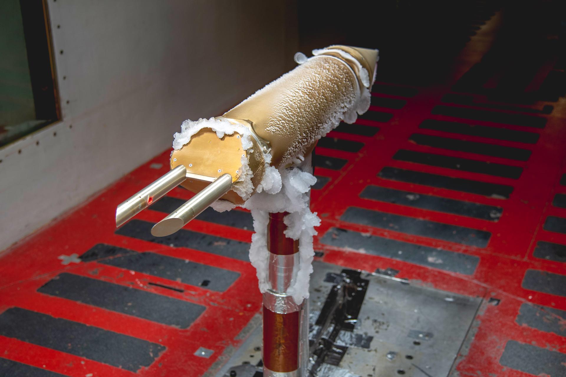
Ice collection seen on un-heated sections of the 1D2D-X ice drop detection probe in the test section of the IRT (Icing Research Tunnel). Drop Size Probe testing – SFD (Subsonic Flight Demonstrator) of SLD (Supercooled Large Drop) Instrumentation Test in IRT (Icing Research Tunnel) – Particle Size Distribution Entry, June 8-11, 2026 Large Drop Testing in IRT
Credits: NASA/Quentin Schwinn
NASA is leveraging its expertise and enhancing its test facilities to help address a rare but persistent aviation hazard: icing that occurs when aircraft encounter unusually large, very cold water droplets in clouds.
The problem, known as “supercooled large droplet icing,” occurs when aircraft fly through clouds containing unusually large drops of water that are very cold but remain liquid. When a plane passes through those drops, they can rapidly freeze to surfaces that are not protected from ice buildup.
With a series of tests in the Icing Research Tunnel at Glenn Research Center in Cleveland, NASA researchers are helping U.S. industry better understand the phenomenon.
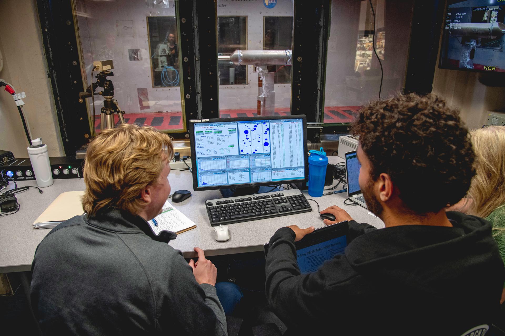
SFD (Subsonic Flight Demonstrator) of SLD (Supercooled Large Drop) Instrumentation Test – Particle Size Measurement in the IRT (Icing Research Tunnel), June 8-11, 2026. Drop size shown on computer from Drop Sizing Probe seen in the IRT test section.
NASA/Quentin Schwinn
Supercooled water is common in clouds – droplets can go below 32 degrees Farenheit but not freeze unless they encounter dust or other tiny particles around which they can crystalize. Aircraft are designed to encounter typical icing conditions where droplets range from 2 to 100 microns in diameter (for comparison, a human hair is about 70 microns wide). But in rarer cases, clouds can contain supercooled large drops up to 2,000 microns in diameter (if you’ve ever been caught in freezing rain, you’ve encountered these droplets at ground level). These much larger droplets can hit or splash to the aft of an aircraft, including areas behind conventional ice protection systems.
The aviation industry relies on engineering tools to help design their aircraft. Current tools work well for typical clouds, but engineers have questions about how well they account for the physics of supercooled large drops. To help answer those questions, NASA is working to enhance the equipment it uses to generate and measure experimental clouds for testing in the Icing Research Tunnel.
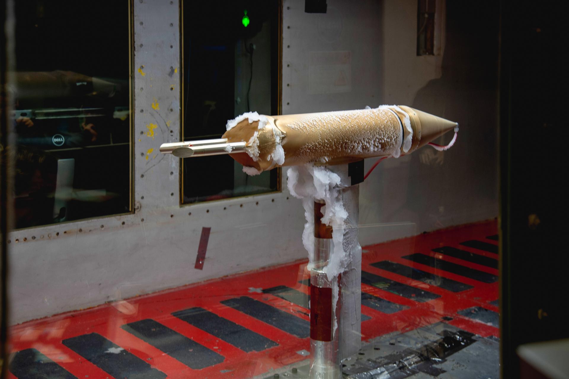
Ice collection seen on un-heated sections of the ice drop detection probe in the test section of the IRT (Icing Research Tunnel). Drop Size Probe testing – SFD (Subsonic Flight Demonstrator) of SLD (Supercooled Large Drop) Instrumentation Test in IRT (Icing Research Tunnel) – Particle Size Distribution Entry, June 8-11, 2026
NASA/Quentin Schwinn
NASA researchers have experimented with brand new probes that help calibrate the sizes of the drops in the clouds the tunnel produces. The probes can “see” drops larger than 45 microns and perform a real-time analysis of their sizes. NASA will compare these results, a laborious technique of post-processing droplet size image data from the tunnel. The results will be mated to results from a different probe that measures droplets smaller than 45 microns. With this, the complete droplet size spectrum is known.
The test campaign marks an important milestone for the Subsonic Flight Demonstrator project, part of NASA’s Research and Technology Mission Directorate. Detailed analysis of the collected data continues, and NASA’s project team will share results with the broader aerospace community once complete.
NASA has awarded Modulate Space Corporation a contract to develop key elements of a 5G communications system for use on the lunar surface with built-in Wi-Fi 6, for NASA’s Glenn Research Center in Cleveland.
This accelerated effort is organized into two primary work areas that together will develop a scalable, standards-based communications capability designed to support future Moon Base surface operations.
The 5G System and Lunar Surface Communications Evaluation and Radio Propagation Measurements contract is a firm-fixed-price contract with a value of approximately $38 million. The performance period for the 5G Network-in-a-Box Development and Lab Demonstration runs from Thursday, Oct. 1, through Jan. 31, 2028. The performance period for the Lunar 5G and Wi-Fi Integrated Surface Network and Flight Demonstration on the Lunar Surface runs from Monday, Nov. 30, through Dec. 31, 2028.
Through these demonstrations, NASA will acquire technology development of hardware, firmware, and software needed to advance the integrated lunar communications system. This effort will give NASA insight into the system architecture and operational performance while providing the flexibility needed to evolve the technology for future lunar surface communications.
For more information about NASA and agency programs, visit:
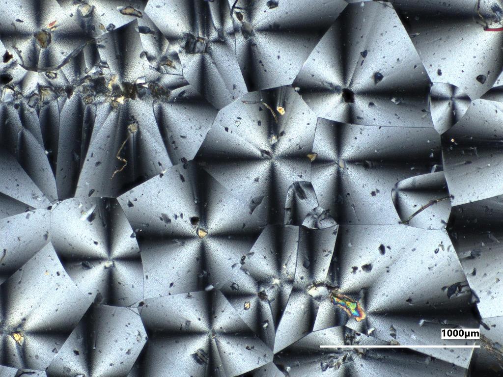
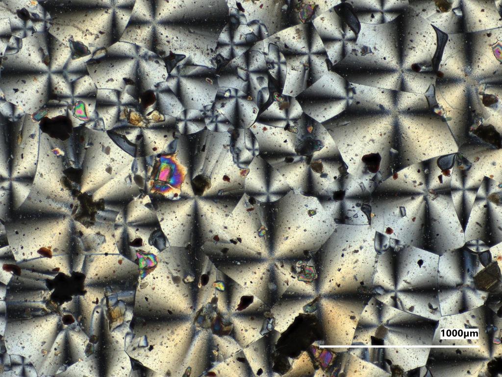
Photos taken using a microscope reveal the colorful, kaleidoscope-like crystal structure of a new NASA-made material that could be used for manufacturing during future space missions. Developed at NASA’s Glenn Research Center in Cleveland, the material could be created directly on the Moon or Mars, allowing NASA to pack fewer supplies — saving weight and reducing launch costs.
To make the material, research chemical engineer Allison Christy and her team of summer interns at NASA Glenn — Tyler Klinchuch, Ethan Bilodeau, and Emma Levenson — mixed a special plastic with simulated Moon and Mars dust. This plastic is biodegradable and could be produced by bacteria fed with crew waste or carbon dioxide.
“The plastic literally grows within the bacteria’s little bodies,” Christy said. “It’s really cool.”
The team found that incorporating simulated lunar and Martian dust particles into this plastic made it stronger and easier to process. Adding different types and amounts of dust allowed them to adjust the material’s properties. The gray image shows sample material manufactured using mock Moon dust, while the reddish image shows material made with mock Mars dust.
The material could be used to manufacture equipment used inside future Moon or Mars habitats, like structural brackets, wrenches, or chairs. By potentially enabling on‑demand, fully recyclable fabrication with lunar surface material, this could help advance NASA’s objective of a permanent Moon Base by reducing resupply needs and empowering crews to build and repair essential equipment on-site.
“You can’t just bring everything with you to the Moon or Mars,” Christy said. “If something breaks, you have to find a way to fix it with what you have. This is a very versatile material, which is a huge benefit.”
Going forward, the team hopes to analyze whether this material could also be used outside in the harsh environments of the lunar or Martian surfaces.
The material is now undergoing testing in Glenn’s Lunar Environment Structural Test Rig to see how it holds up in extreme temperatures. Several samples are also slated to launch aboard the upcoming Materials International Space Station Experiment 23 (MISSE-23) mission and will be exposed to intense conditions outside the station.
This research is funded through NASA Glenn’s 2026 Center Innovation Fund, which is managed by the agency’s Research and Technology Mission Directorate.

 Login