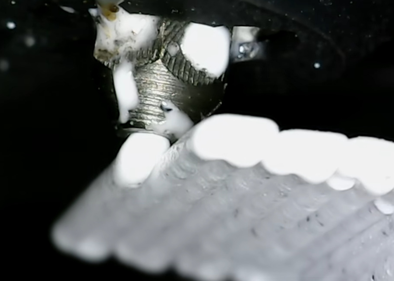
As FDM printers keep getting faster, we are forced to deal with a range of bottlenecks, all of which conspire to hold us back from another Benchie world record. A major physical limitation is that of flowrate, as the hotend has to be able to melt the filament that enters the nozzle before it departs said nozzle. One attempt to make a high-flow nozzle involves splitting the material path into three winding sections, which theoretically should help said flowrate. Recently [Thomas Sanladerer] took a poke at this and other types of nozzle with SLS-printed nozzles.
These printed parts still needed some finishing on the lathe, including drilling the 0.4 mm nozzle hole. The finished nozzles feature a variety of internal geometries, including the aforementioned triple-path, as well as many with various intrusions that seek to maximize the contact area.
Using a Prusa Core One these nozzles were subsequently tested to see what print quality they produced at high flow rates. A special test rig to test the nozzle pressure was also used to further characterize them, as this indicates at which flowrate the nozzle begins to struggle. Among these the Fuge design did the best, though with the big asterisk that these nozzles were printed in MS1, which is in effect tool steel and thus not great for being nozzles.
A fun part of modifying something like a motorbike is that you sometimes have to come up with creative solutions to basic questions, like how you can still access the fuel tank’s cap after extending it forward. In the case of [KRTframework] this meant that the fuel cap was now underneath the bodywork, requiring a suitable way to access it. Of course, this meant making a hidden access panel with a custom hinge, to not break the bike’s clean lines.
To make the process as easy as possible, a 3D scanner was used to get detailed measurements on what the new bodywork would look like. Using these the new bodywork was created, including what would be the hidden access panel, yet finding a suitable hinge mechanism wasn’t easy. This is where this custom design was created, with detailed assembly covered in the video.
To bridge the gap between the opening and the fuel tank a part was 3D-printed that also contains the simple push-to-open latch mechanism. Of course, in the comment section people sounded off on this, feeling that it would be far too easy to accidentally open the panel.
The hinge seems to be well-received at least, with it having to fit within the available space, while also providing good access to the fuel cap when opened, meaning quite a lot of travel.
You can 3D print all kinds of things, from Yoda heads to little models of Pikachu. Eventually, though, most of us get to a point where we want to print something a little more interesting. The lenticular prints developed by MIT CSAIL are very much that. (h/t Core77).
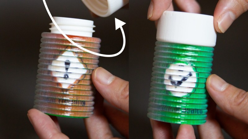
The ShiftLens concept is simple enough—there’s a lens layer printed in transparent material. Beneath that, lives a patterned layer in alternating colors, corresponding with the linear lenses of the layer above. Then, there’s an actuation mechanism that can shift the lens layer relative to the pattern layer. This creates a changing color effect as the mechanism is shifted. The actuation mechanism can be a knob, switch, or roller—anything that moves the layers relative to each other. On its own, it’s a bit of a curio—but there are some fun demos. In particular, using the lenticular printing on a bottle to form an indicator for when the container is closed properly. There isn’t a publicly available design tool for these prints yet, though the team developed one for Rhino that they used internally for the project.
It’s a pretty interesting application of 3D printing, and one that we fully expect a bunch of YouTubers to replicate within the month. We’ve featured some other great print hacks lately, too, like a slicer that lets you print horizontal overhangs without support. Video after the break.
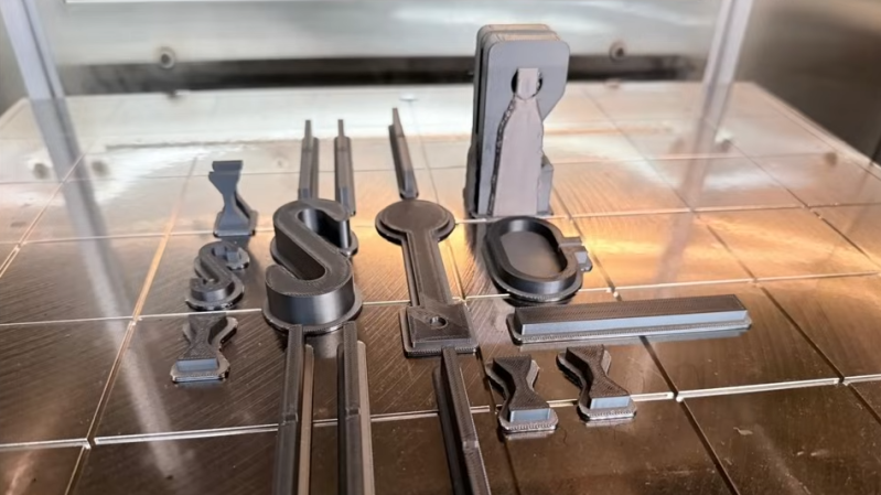
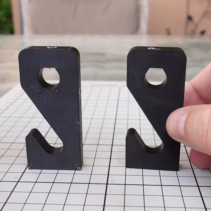
[Igor] of [My Tech Fun] set out to discover what differences, if any, can be found between parts printed in PC-ABS filament on an industrial 3D printer, and those from prosumer-grade machines and filament. His video is full of his usual attention to detail as he compares a test suite of parts printed at home in Polymaker PC-ABS with those from a Stratasys Fortus 450mc using proprietary PC-ABS filament.
PC-ABS is a filament that strives to deliver the benefits of both polycarbonate and ABS. It’s durable and has fantastic impact resistance, but it costs a bit more than either PC or ABS and requires a heated chamber.
In the end, PC-ABS from a home printer compares favorably to an industrial system, at a fraction of the price.
[Igor] has previously compared industrial ABS with comsumer ABS, but what made him curious about PC-ABS in particular was the large difference in print temperatures between Polymaker PC-ABS, and Stratasys’s own proprietary PC-ABS.
[Igor] prints Polymaker filament at 280º C in a 60-65º C chamber, whereas the Stratasys filament prints at 325º C with a chamber temperature of 95º C. That’s quite a difference. The industrial printer has over double the print time, to boot. Would test objects printed from the industrial filament, on an industrial machine, be noticeably different from those printed at home?
To find out, [Igor] orders a test suite of parts from a company with a Stratasys Fortus 450mc (who was also kind enough to take a short video of the machine in action) and prints his own on both a Prusa Core One L, and a Bambu Labs H2D. He then proceeds to compare them in a variety of ways while testing them to destruction.
What’s the bottom line? The industrial prints have better dimensional accuracy, but the home prints have the edge in appearance. When it comes to performance the differences are mostly minor, and not always in the industrial system’s favor. Broadly speaking, PC-ABS from the home workshop compares very favorably from an expensive industrial system and proprietary filament, at a fraction of the price. See it for yourself in the video, embedded just below.
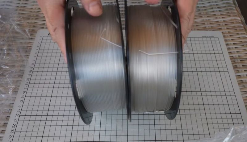
The average 3D printer owner knows a few types of filaments – PLA, ABS, somewhere in the middle, PETG. PCTG is another option that can be confusingly similar to PETG. Recently, [Igor Gaspar] of [My Tech Fun] took a poke at both types. He obtained both PETG and PCTG transparent filaments from the same manufacturer to compare them directly.
As we recently detailed in an article on PET polyesters, PETG is glycol-modified PET, meaning that some of the glycol monomers are replaced by CHDM monomers to create a more flexible and robust material. PCTG is very similar to PETG, except that more than half of the glycol monomers are replaced rather than less than half. This creates a PET-type material that has distinct physical properties from PETG, which might be desirable for some applications.
PCTG is more ductile due to the addition of more CHDM, but also requires higher temperatures to print, closer to ASA presets. During testing, it’s obvious that PCTG is indeed much more flexible, making it potentially a good choice for springs and compliant mechanisms. PCTG is also highly impact-resistant, unlike PETG, and resists higher temperatures much better.
Overall, other than the higher printing temperatures, PCTG seems like a solid option for more extreme environments, potentially as an alternative to ASA and similar filaments.
Resin 3D printing has opened up a whole new scale of resolution for hackers, but the technology can go still finer; commercial micro-SLA and two-photon polymerization printers can print items with sub-micron feature sizes, but the machines are well out of reach for hackers. There’s more than one way to get such high resolution, though, as [Diffraction Limited] demonstrated with his micron-scale resin printer.
The printer builds on [Diffraction Limited]’s previous micro-manipulator and fiber-coupled laser. The micro-manipulator holds the end of the optical fiber just in front of the build plate, which is coated with resin. A 405-nm laser shines through the fiber, curing the resin in a narrow cone in front of the fiber’s core, which the micro-manipulator can trace in a pattern to build up objects, much like an FDM printer. Since the fiber’s inner core is only three microns across, the cured resin shears cleanly away from it when the fiber moves. Since the principle is so similar to an FDM printer, a standard slicer could be used to generate the tool paths.
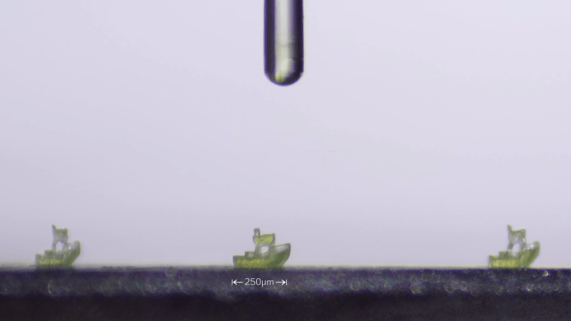
Early testing proved that the principle worked, but the resin wasn’t absorbent enough for very high resolutions; UV light passed through previously cured resin too easily, limiting the minimum layer height. A UV-absorbent dye dissolved in the resin solves this by limiting the light’s penetration depth. [Diffraction Limited] found that curcumin, the natural dye responsible for turmeric’s bright yellow colour, worked well for this; as an added bonus, alcohol easily extracts it from turmeric powder. This solved the resolution issues well enough for [Diffraction Limited] to print a series of Benchies 150 µm long, a Stanford bunny dwarfed by a human hair, and a few other microscopic pieces. Conveniently, the curcumin dye leaves the printed objects slightly fluorescent under UV light, making them easier to pick up under a microscope.
Large prints have a risk of warping, by which we mean corners can lift off the print bed as the object sort of curls inward on itself. It’s not always due to poor filament quality or an unclean build plate. Sound like something you’ve dealt with? Check out this handy roundup to understand why it happens, and learn ways to prevent it.
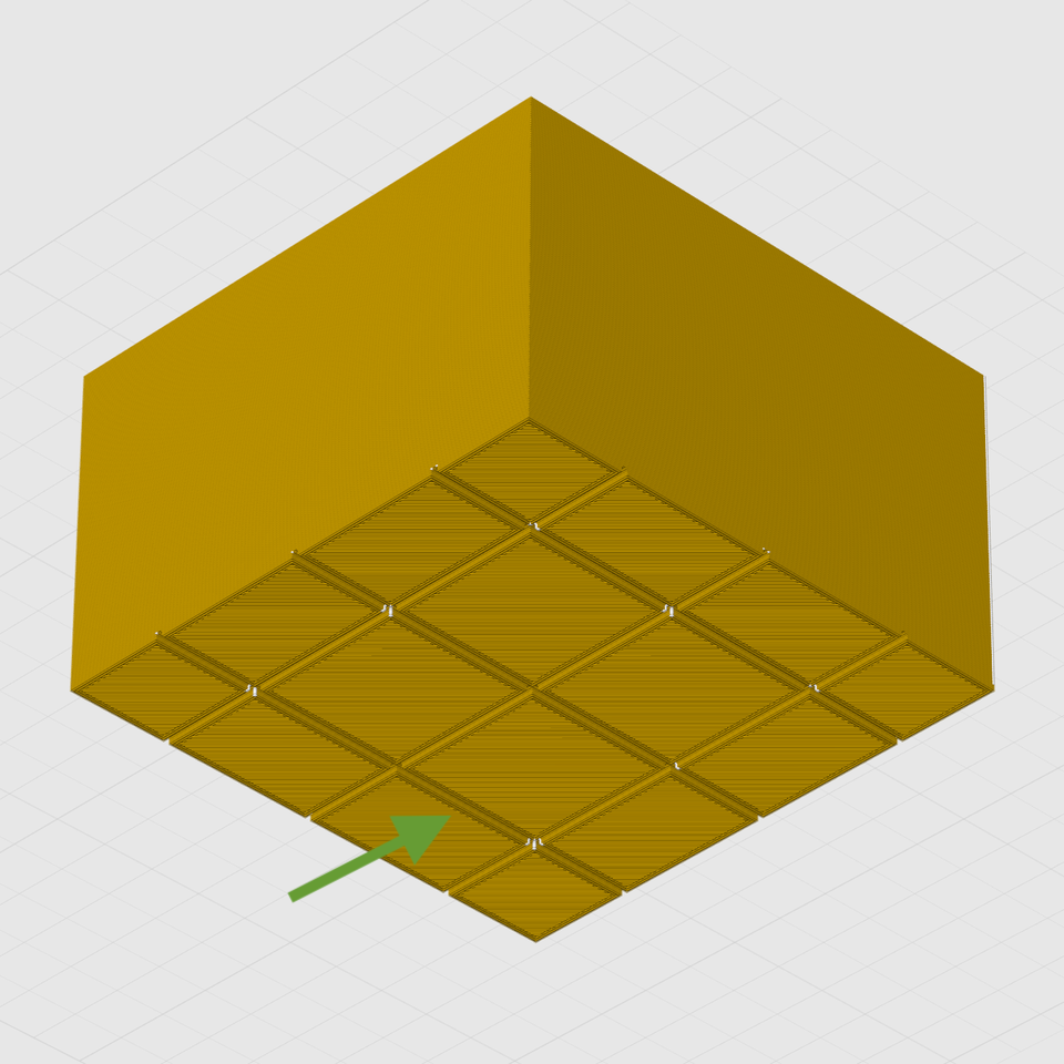
A big flat area with sharp corners is susceptible to warping. Breaking the footprint into a grid pattern helps distribute stresses instead of concentrating them at the corners.
The reason some objects have trouble while others don’t is physics. Deposited plastic shrinks ever so slightly as it cools, and some shapes — like wide, flat surfaces with sharp corners — are worse for this than others. This sort of problem is what the guide addresses with a number of techniques.
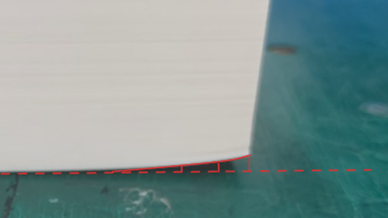
Some are simple, like turning on brims which increases an object’s footprint. This increased surface area offers more adhesion, but also increases heat transfer from the print bed into the model, slowing the cooling process. Thinner walls and an altered infill pattern is another option. Other techniques are more complex.
The most effective methods involve modifying the model itself to reduce or eliminate stress points. One such method is to break the model’s footprint into multiple zones with a shallow grid. Instead of one big flat bottom, the object has multiple smaller ones. Because big flat areas are more susceptible to warping than small ones, turning the bottom into a grid pattern helps spread those stresses out and prevent lifting.
If you design your own models, you’ll find several design tips worth keeping in mind. It’s always smart to practice good DFM (Design For Manufacturability) which means taking 3D printer strengths and weaknesses into account when designing an object. In this case, it can help prevent print failures. Good DFM can also make parts much, much stronger just by designing in the right features.
Over the time Hackaday has been in existence, the art of 3D printing has evolved from a relatively crude hit-and-miss affair to something approaching what we all imagined back then. You can’t yet walk up to a Star Trek replicator and ask for a part, but a modern state of the art consumer or prosumer grade printer will deliver consistent high-resolution parts, and in a surprisingly short time. [The Next Layer] asks whether consumer FDM printers have now reached the point at which they’re about as good as they’re going to get, and whether other technologies hold the future.
It’s a fair point to make that the resolution of a consumer FDM printer may be close to its mechanical limit. Techniques such as input shaping and the adoption of better CoreXY mechanisms mean that prints which once might have relied on SLA can be done in FDM. Healthy competition in the marketplace has delivered high quality colour printing, with tool-changing printers being no longer solely the preserve of the professional. He uses the example of a mobile phone to make the point that new machines have less of a wow factor to deliver, as increments have become less grand.
It’s a persuasive argument, and looking at the printers around us we can see it in action. The difference in ability between a 2020-ish and a 2026 FDM printer are far smaller than those between the same time periods in the last decade. Compare a MakerBot Cupcake and an Ultimaker II, or the Ultimaker and a Prusa Mini, and each is light years ahead of the last. But the best the Mini can do is surprisingly not as far behind as you’d expect to that of their latest, or of the equivalent from Bambu Labs.
Does this means that nothing new is coming in 3D printing? Of course not. UV printing is coming through and will deliver incredible results, as will SLS printing. It’s interesting he devotes little time to SLA printing, perhaps because it’s not as easy a process as FDM. He makes the point that we’ve never had it so good, as the high-end FDM features will appear in modestly priced machines, and we have those other technologies to look forward to.
It’s an interesting discussion, and you can see it below the break.
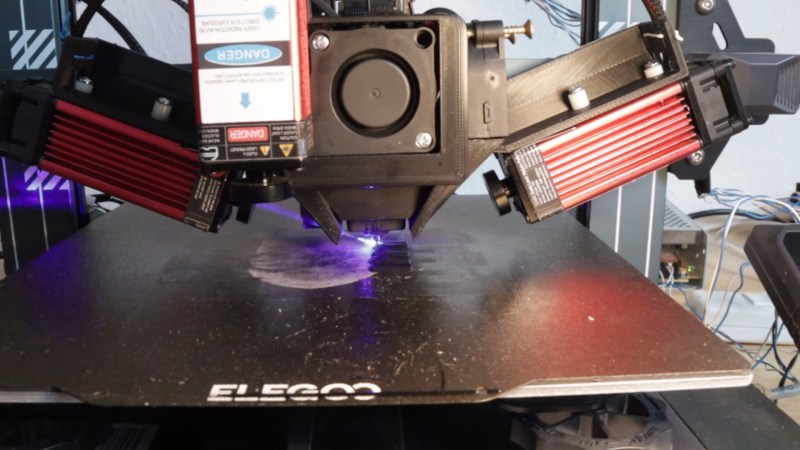
Now, not everyone minds the characteristic layer lines you get with Filament Deposition Modeling (FDM) 3D prints, but sometimes you need a smooth surface. If so we might go for filling primer, Bondo, or maybe break out the ABS and vapor smooth. Well, [I changed a thing] has an alternate suggestion: lasers. Laser melting can smooth the walls on a print, or the top surfaces as he shows in two different videos, both embedded below. The results look roughly similar to vapor smoothing, without the chemical exposure small risk of explosion.
Of course, you need a laser to do this, and [I changed a thing] has two diode lasers mounted to the X-axis of his printer. Of the two, the top surfaces were a lot easier to get right than the wall smoothing, which makes sense. Top surfaces are right there for the laser to get at, after all, while with his laser setup [I changed a thing] needs to get at the walls obliquely. [I changed a thing] tries melting layer-by-layer as well as a few methods to get at the walls of a finished print; which works best seems to depend on the size of and geometry of the object, so it looks like this technique is as much art as science right now.
This effort is closely related to the previous work [I changed a thing] did on improving layer adhesion with laser melting. It’s also not the first time we’ve seen laser-driven print smoothing, but that project used non-planar movements to do a post-print laser pass.
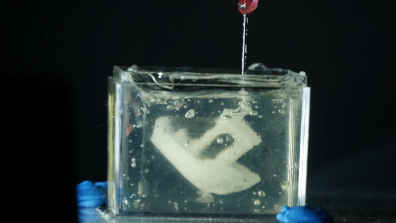
There’s plenty of substances that can theoretically be extruded from a nozzle, but only a regrettably small subset of them can actually be used for 3D printing. One limiting factor is the liquid range: too high a melting point and it’s hard to reliably extrude, too low and it tends to ooze and flow once extruded. Embedded 3D printing offers a way around this: it submerges the entire print in a shear-thinning support gel which keeps liquids in place until they solidify. [Riley] of Riley’s Lab recently built such a 3D printer and used it to print in silicone and epoxy.
In place of the extruder, [Riley] mounted a mostly 3D printed syringe pump, which allowed him to squirt out almost any liquid. For a test, he printed a tardigrade model out of cream cheese. This was a good test material for several reasons: it’s cheap, easy to extrude, and holds it shape well after extrusion. Silicone and epoxy, however, won’t hold their shape, which is where the support bath comes it. This was a mixture of mineral and vegetable oil, with some fumed silica added to make it thick yet shear-thinning. This lets it contain the extruded liquid, yet flow as the extrusion needle slices through it.
For the first test, [Riley] printed a Benchy out of Sylgard 184. The outcome looked good in the bath, bar some stringing, but it seemed to have limited adhesion between layers, and disintegrated upon removal from the bath. A second test with a two-part epoxy worked much better; it also had some stringing, but it held together while the bath was washed away in isopropyl alcohol, and even seemed decently shock-resistant afterwards.
It’s great to see a hacker working on this technology; we’ve previously covered a commercial take on it, as well as some of the research that led to it.
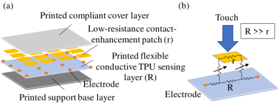
Schematic diagram of the touch-sensitive skin. (Credit: Haofeng Chen et al., ArXiv, 2026)
Hypoesthesia, more commonly referred to as numbness, is one of the more distressing ailments that can affect us humans, primarily because it reminds us of just how much we rely on our sensation of touch in daily life. From experiencing the world around us, handling objects, noticing when you just bumped into that side table again and the comforting hug of a fellow human being, touch is perhaps the most important of our senses.
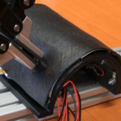
In that regard the recently published research by [Haofeng Chen] et al. on giving robots a skin that can experience touch seems rather important as it would give especially humanoid robots a more natural way to interact with their environment, using feedback from touch.
Poking the artificial skin. (Credit: Chen et al., arXiv, 2026)
One of the essential parts of biological skin is that it is teeming with sensors, at a density level that provides excellent resolution as required, down to sensing e.g. small surface imperfections with one’s finger tips. Replicating this with an artificial skin for robotics has always been a problem, due to the wiring and/or reliability nightmare this poses with typical approaches. Instead of focusing on many individual sensors, [Chen] et al. focused on effectively creating the equivalent of a resistive touch screen in skin format.
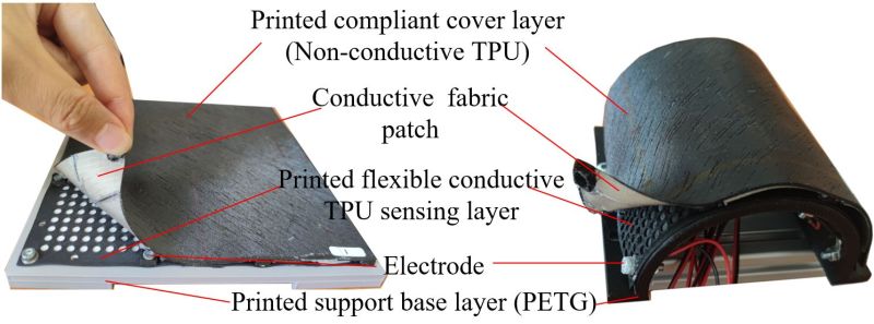
The basic principle underlying the demonstrated artificial skin is electrical impedance tomography (EIT), which uses surface electrodes to form a tomographic image based on measures electrical resistivity. Core here is the flexible TPU layer with electrodes and the conductive fabric patches attached to the top TPU cover layer. The electrodes continuously measure the resistivity, with disturbances from those patches due to touch events on the cover layer altering these values. From this EIT can be used to reconstruct the location and strength of the touch event.
The results from the created prototypes were promising, with only 16 electrodes sufficing to create a fairly accurate pressure map. Hardware-wise this makes it thus quite uncomplicated, with the characterization of the TPU porosity and such along with the EIT algorithm (provided in the paper) probably being the biggest hurdles for hobbyist recreations.
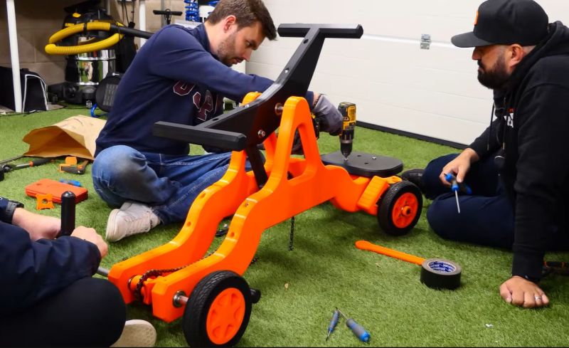
It’s arguably adult-sized. (Credit: Sam Barker, YouTube)
A staple of old movies featuring railways, many handcars – also called pump trolleys or pump cars – feature the characteristic seesawing beam. Requiring at least two people, the motion of this beam is subsequently converted into the rotating motion of the wheels, propelling it at a leisurely pace across the tracks. As a fun and yet functional mechanical contraption it also makes for an entertaining 3D printable project, which is what [Sam Barker] and [Tom] did.
You can find the entire project over at Printables if you are feeling the itch as well, though as of writing details on the required bolts and shafts are still pending.
Since the entire assembly had to be lugged over to the Open Sauce event in the US, they had to design it to be small enough to fit into check-in luggage and easy enough to reassemble in a hotel room. Naturally this put some constraints on the full size of the contraption, with it omitting compatibility with standard gauge railways and also being decidedly fun-sized.
That said, it seems to have left an impression on the folk over at Open Sauce, and it’s hard to argue with the sheer fun factor of such a co-op mode of transportation. Even if bicycle-style handcars are more popular these days, especially for tourist purposes, the old seesaw-style has that certain charm to it.
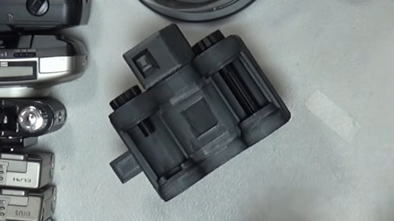
Making a film camera is a project within the reach of almost anyone, from the experimenter with cardboard and sticky tape, to the machinist with an aluminium billet. But 3D printing has opened up the world of cameras to whole new set of experimenters, and we’ve seen some very impressive builds here as a result. For all that, there’s always been a particularly tricky aspect to a home made camera: the shutter. In particular, making one with variable speed has proved almost impossible. Now [Camera Things] has given it a very good shot, with a sliding 3D printed design.
To cock it, both the strips are pulled across, before the blind strip is pushed back, and the shutter operates by sliding back under the influence of a rubber band. The clever part in this case is that the blind strip can be partially pushed back to affect the size of the shutter opening. The effect is then of a variable width strip of light passing over the film, which is equivalent to varying the speed of a conventional shutter.
Due to space constraints he’s only able to make it a half frame shutter, so he’s abandoning this design in favour of a more complicated set of vertical leaves. Sadly he’s not made the files available, but we thing proficient CAD users should be able to make their own version. The video is below the break.
Over the years poly(lactic acid) (PLA) – also known as polylactide – has become a popular thermoplastic for a variety of reasons. One of these reasons is that it’s easily produced from a renewable resource, i.e. lactic acid, with the resulting polymer even being compostable if you assume that your compost pile hits a steady 65°C or more, well above the polymer’s glass transition temperature (Tg).
That said, PLA by itself is a pretty crummy material, being exceedingly brittle and inferior to common alternatives like PET(G) in many metrics. Over the decades much research has gone into figuring out this material, its amorphous and crystalline states, as well as how to use plasticizers, copolymers, mechanical manipulation and PLLA/PDLA blends to produce more useful variants of PLA.
Today’s spools of thermoplastic filament that gets marketed as ‘PLA’ are the result of such engineering, though with plenty of remaining issues, as anyone who has struggled through a spool of brittle PLA filament can attest to. Although you can find plenty of tips online about how you should ‘just’ toss said spool into an filament dryer, oven or similar to bake it – with accusing fingers pointed at moisture intrusion, hydrolysis and kin – it helps to understand the fundamentals of how PLA works, and how it degrades.
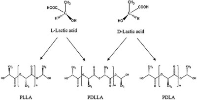
Although we use the generic acronym of ‘PLA’, there are actually two chiral forms of poly(lactic acid). Generally the one that we most commonly find in our spools of consumer-grade PLA filament is poly(L-lactide) (PLLA), while its more rare chiral form is poly(D-lactide) (PDLA). These match their chiral lactic acid forms, being L-lactic acid and D-lactic acid.
If both PLLA and PDLA are combined into a single polymer chain you thus get another type of material with its own set of properties. Overall this PDLLA polymer is quite stable, preferring to stay amorphous while still resisting hydrolysis better than its other polymer forms.
While industrial production of D-lactic acid is possible, most production is in the form of cheaper L-lactic acid, with correspondingly FDM printer filament thus having a high chance of being PLLA. This, along with factors like the ratio of crystallinity versus amorphous areas determines the initial state of the material.
These two states, of crystalline versus amorphous are defined by the state of the polymers, with the crystallized state being the most stable form that is most resistant to degradation through hydrolysis, yet this state is also the most rigid and thus most brittle. This is of course just the beginning of all the fascinating materials science.
Polymer Types
While just the basic PLLA and PDLA polymers already provide a lot of fascinating materials science, there is a whole world of things you can do with these polymers. We already touched on blending PLLA and PDLA, whereby both types of polymers support each other. This same blending can be done with other types of polymers as well, to further modify the properties of PLA, with many of the essentials covered by Vincent DeStefano et al. in this 2020 paper.
In addition to blending polymers, we can also create copolymers, whereby PLA monomers are mixed with other monomers to create a new polymer type with certain desirable properties, like enhanced flexibility. This already gets us right in the territory of the countless additives for PLA to modify its plasticity, nucleation and other characteristics.
Of note are the different crystallinities of PLA, as also covered by DeStefano et al., starting with ɑ and ɑ’-crystallinity as the most common types, and a PLLA/PDLA blend being fully amorphic if it contains more than 10% of PDLA. Since most PLA blends tend to have less PDLA than this we generally classify PLA filament as semi-crystalline.
Plasticizing
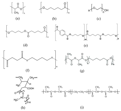
Structural formulas of PLA (a), PCL (b), poly(ethylene glycol) (PEG) (c), PBA (d), PBAT (e), PBS (f), block copolymer of poly(L-lactide-co-ε-caprolactone) (PLA-PCL) (g), graft-copolymer of poly(lactic acid)-g-natural rubber (PLA-g-NR) (h) and triblock copolymer of poly(D-lactic acid-co-ethylene glycol-co-D-lactic acid) (PDLA-PEG-PDLA) (i) (via Mastalygina et al., 2024, Polymers)
Unsurprisingly, most of the additives and modifications to PLA focus on plasticizing it, which can be done through a number of methods in addition to modifying the amount of PDLA in the blend. A good overview of these methods can be found in this 2024 paper in Polymers by Elena E. Mastalygina et al..
Beyond PDLA/PLLA blends we can also blend in other polymers, including a range of flexible polyesters, though it’s essential to determine intermolecular compatibility. Common here are polycaprolactone (PCL), polybutylene adipate terephthalate (PBAT) and polybutylene succinate (PBSA), which like PLA are biodegradable polyesters.
Where things get interesting is with copolymers, which can also involve the aforementioned PCL, PBAT, etc., as well as polyethylene glycol (PEG), with a wide range of combinations possible. Some of these combinations are summarized in the graphic to the right from said paper by Mastalygina et al. using data from cited papers.
Although these methods, along with the more experimental structural modification approach, make the base PLA polymer more flexible, it’s also possible to introduce oligomeric and low-molecular-weight plasticizers which essentially wriggle into the PLA polymer matrix, thus increasing its mobility.
Another focus of such additives can be to act as nucleation agents for nano-crystallization, creating small spherulites that do not impact plasticity nearly as much as naturally forming large spherulites.
Plasticizer
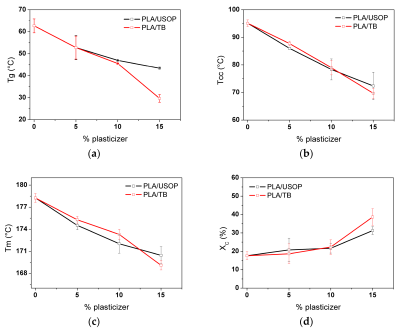
TB and USOP as plasticizer are quite similar: (a) Glass transition temperature (Tg), (b) Cold crystallization temperature (Tcc), (c) Melting temperature (Tm), (d) Crystallinity degree (Xc). (Credit: D’Amico et al., Polymers, 2025)
The aforementioned paper covers a range of these plasticizers, such as PEG. Here a problem is that although PEG as a plasticizer additive does promote PLA ductility, PEG tends to migrate out of the polymer. Fortunately there is a dizzying amount of possible plasticizers here, ranging from lactic acid oligomers to epoxidized sunflower oil, as well as linseed, cottonseed, soybean, castor, and other oils.
In a 2025 paper in Polymers by D’Amico et al. the use of used sunflower oil (USOP) as PLA plasticizer is compared with the conventional plasticizer tributyrin (TB). Both show a very similar effect on the plasticity of the final product, though long-term stability of the plasticizer was not tested.
Of course, determining which plasticizer was used in any off-the-shelf spool of PLA filament is effectively impossible. A quick look at a number of commercial PLA filament options, ranging from Prusa to Bambu Lab, shows that their material safety data sheet (MSDS) lists the material only as ‘PLA with additives’.
In a way this makes even ‘regular’ PLA about as much of a mystery filament as so-called ‘PLA+’, with its arbitrary additives such as calcium carbonate.
Degradation
As for how that spool of filament degrades, we can thus draw a number of conclusions. The first is that hydrolysis is the primary degradation mechanism, gradually shortening the backbones of the polymer chains. Yet the other type is one that happens regardless of whether the PLA is fully dried and stored in a container of some sort. A good example of this can be found in e.g. a 2021 Polymersresearch paper by Tien-Wei Shyr et al. in which many variations of additive-free PLA samples were stored for multiple years.
One set of samples was put into zipper bags and stored in a vacuum-free desiccator, while the other set was stored in vacuum-sealed bags. Both sets were stored like this at room temperature for three years, after which their crystallization and hydrolysis levels were checked.
For the vacuum-sealed samples there was no significant degradation compared to the received samples, while the three-year old samples in the zipper bags had degraded significantly, suffering hydrolysis, nucleation and corresponding crystallization and thus brittleness.
Brittleness
A very unhappy spool of PLA filament. (Credit: Maya Posch)
When I recently did some FDM printing for a comparison article series with SLA resin printing, I had dug up a spool of white Sunlu PLA filament that I had left kicking around for probably around three years. This spool had seen itself stuck exposed to room conditions for at least a year when I noticed that after letting it sit fed into the extruder for a number of hours would result in it snapping.
Although I could still print with this filament if I didn’t let it sit too long, it was clear that not only was the PLA rather brittle at this point, it also had assumed a very strong preference for staying in the shape that it was in while on the spool.
What this suggests is thus two things: significant hydrolysis had weakened the filament, and increased crystallization had resulted in both rigidity and brittleness.
Unknown is whether something like a PEG plasticizer was used with this filament, with it having left the building somewhere in the past few years. If the plasticizer is no longer present that would obviously pose somewhat of a conundrum with any attempts to revive the filament.
Ultimately what one can do here is to heat the filament above its Tg for a number of hours, so at least 65 °C for the average PLA blend. This should restore the semi-crystalline state somewhat, although if enough damage has been wreaked by hydrolysis all bets are off. For this particular spool of PLA I did toss it into a Chitu Filapartner filament dryer as it allows you to set the temperature and time, but without a good way to measure the internal material temperature it may not have gotten hot enough.
Considering that this old spool of PLA was fully dried about a year prior in a Sunlu filament dryer using its PLA preset, followed by it being stuffed into a vacuum bag and into an ‘airtight’ container, it’s likely that most of the damage was indeed done by 1-2 years of exposure to room air.
I have saved a few samples of this old filament for later study, but in light of the research covered in this article it highlights just how hard the materials science is, even when it comes to a material as mundane as PLA. Ultimately the best you can do is keep it in that nice vacuum-sealed bag when not printing and pray to the 3D printer gods that you didn’t overlook something important and that maybe one day the filament manufacturers will bless us with details on what these ‘additives’ are.
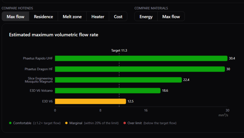
When it comes to 3D printing in the FDM world, you can go a long way just relying on standard settings that ship with your 3D printer and/or slicer. If you want to push the limits, though, it pays to better understand the hardware and materials you’re working with to know what you can get away with. To that end, [Robert Samples] put together the MeltCalc database to help.
The purpose of MeltCalc is simple—it collates data on hot ends and materials regarding factors like maximum flow rate, print speeds, and heater requirements. If you’re wondering whether a given hot end can flow a given filament at a given rate, for example, this tool is a great place to start. It features 64 different hot ends and 36 polymers typically used in the 3D printing world, and can spit out maximum flow rates and print speed estimations even accounting for fancy tech like Core Heating Technology (CHT) nozzles. It’s all based on thermodynamic modelling which [Robert] put together based on his experience as a chemist who works with polymers. His aim was to provide a tool with realistic flow rates for hot ends, so that end users don’t have to just rely on often-optimistic marketing numbers.
For those eager to dive deeper into the code and modelling, the project source is available on Github. We’ve featured all kinds of other useful hacks in this space lately, too, like our recent look at how to achieve wave overhangs. If you’ve got your own nifty 3D printing tools in the works, don’t hesitate to notify the tipsline.
The fun thing about thermopolymers like PLA is that you can blend in additives, some of which are necessary to make it at all usable, while so many other additives are either just cosmetic or arguably just plain weird. In a recent video, [Zack Freedman] goes over some of the weirdest ones that he’s come across so far.
These range from the pretty-normal-but-unusual, like CMYK sets of filament for full-color printing, to the rather unusual, like very silky PETG and foamy TPU and TPE, all the way to the WTAF ones, such as Timeplast filaments that can be used as soap as well as fish food.
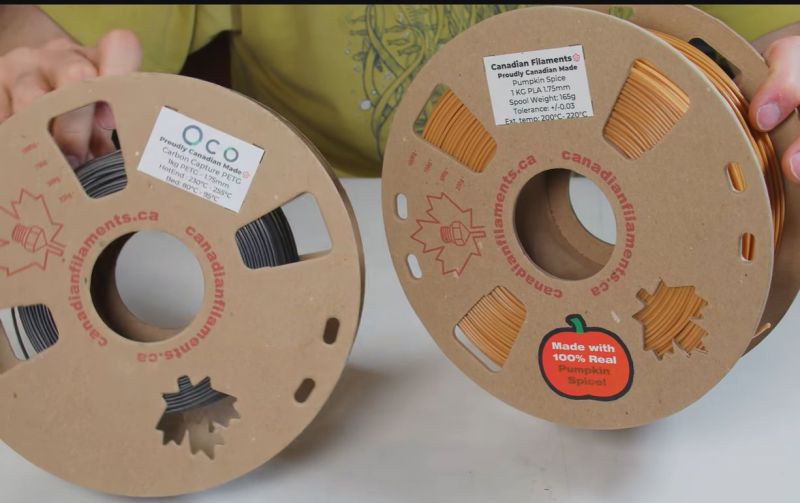
He also tried a range of filaments that vie for being the blackest filament possible, while others pretend to be paper or are made out of literal landfill trash. Some hit your olfactory senses with a hammer by smelling like all the lemons just got squirted right up into your nose, purportedly to keep flies at bay. There is also pumpkin spice-flavored PLA, for when you really need to make the holidays extra fragrant.
Overall, the range of filaments here is quite dizzying, with some being actually practical, while others are mostly about their green credentials, or about being pretty or having a specific olfactory experience. Whether any of them are for you depends. Do you have a longing for 3D prints that smell like pumpkin spice or are fish food? We’ve noticed before that [Zack] likes strange filament.
We’ve heard of wave overhangs before. It is a new technique for printing horizontal overhangs with no supports. Building on some other techniques like arc overhangs. The idea is to teach the slicer not to try to draw overhangs in the middle of free space. Instead, when the slicer realizes there is a horizontal overhang, it tries to “grow” the overhang from the main part. You can see an overview in the video below.
For example, imagine printing a letter ‘T’ vertically. The stem of the T is no problem, but when you try to print the arms it will normally need support. But if you could just print the arms starting at the stem with slight overlapping, the arms could grow as they hang onto either the stem or the last overhang line.
That makes sense, but it only works for very simple cases. Arc overhangs can fill more complex cases, but suffer from little dimples at the center of each arc. The realization for wave overhangs is to replace the arcs with waves as you would see in a pond. The waves diffract around holes and corners.
Perfect? Not quite. They are still experimenting with settings, but there seems to be some increase in warping. If you want to experiment, you can download a fork of Orca and contribute your results to the community.
We looked at this technique earlier, but we haven’t seen much about it in practice yet. Let us know in the comments if you’ve tried it and how it worked for you. There are more details in the paper on the subject, or you can jump right to the software.

 Login
Login
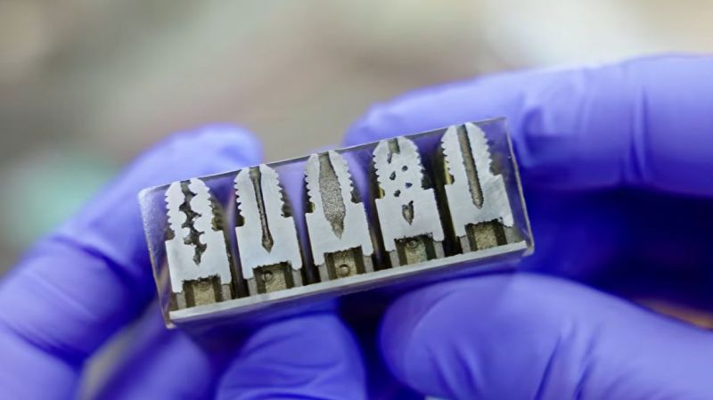
 As FDM printers keep getting faster, we are forced to deal with a range of bottlenecks, all of which conspire to hold us back from another Benchie world record. A major physical limitation is that of flowrate, as the hotend has to be able to melt the filament that enters the nozzle before it departs said nozzle. One attempt to make a high-flow nozzle involves splitting the material path into three winding sections, which theoretically should help said flowrate. Recently [Thomas Sanladerer] took a poke at this and other types of nozzle with SLS-printed nozzles.
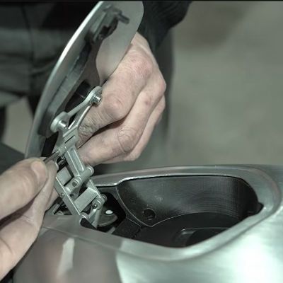 A fun part of modifying something like a motorbike is that you sometimes have to come up with creative solutions to basic questions, like how you can still access the fuel tank’s cap after extending it forward. In the case of [KRTframework] this meant that the fuel cap was now underneath the bodywork, requiring a suitable way to access it. Of course, this meant