❌

Reading view

There are new articles available, click to refresh the page.

NASA Improves Shock, Vibration Analysis
A person sits at a workstation viewing a computer monitor that displays a blue 3D wireframe engineering model of a spacecraft component.
Stirling Allen, part of the Dynamic Environments Group with NASA’s Launch Services Program Office, showcases a commercial digital software at NASA’s Kennedy Space Center in Florida. The software performs finite element modeling to support shock and vibration analysis and ensure spacecraft and rockets can withstand harsh vibration, shock, stress, or other physical forces before launch, strengthening mission safety in the process.
NASA/Clayton Rougelot

Rockets vibrate, shake, and flex intensely as they climb into space, and spacecraft packed with delicate scientific instruments must survive those forces. Before any rocket leaves the ground, NASA engineers work to predict how those stresses will affect every part of a spacecraft.

To do that, engineers in the Dynamic Environments Group with NASA’s Launch Services Program Office at the agency’s Kennedy Space Center in Florida have streamlined how they ensure spacecraft and rockets can withstand harsh vibration, shock, stress, or other physical forces, strengthening mission safety in the process.

Using a commercial digital software tool in a new way, the engineers developed a standardized modeling workflow for finite element modeling to strengthen shock and vibration analysis and ensure hardware is prepared for the extreme environments of launch and ascent.

“This computer-based method helps predict how rockets and spacecraft behave under extreme conditions before hardware is built and helps identify weak spots and potential failure risks early so the team can address the findings,” said Brian Beaver, chief of the Flight Analysis Division with the Launch Services Program Office at NASA Kennedy.

The team recently used the software for the first time while certifying a commercial launch provider’s rocket selected for a NASA mission. The commercial partner provided vibration testing but not shock testing. The Dynamic Environments Group determined shock testing was needed and used a template the group created to run what-if comparisons, visualize structural behavior, and answer complex questions that would have required extensive manual modeling in the past. The team verified the company’s testing results for flight environments, and the analysis provided new insights addressing shock during transport.

“We are using a tool that’s existed for decades, but it’s not normally used by the dynamic environments disciplines,” said Alex Hardt, aerospace engineer with the Launch Services Program Office at NASA Kennedy. “But we’re changing that. We’re using it in a relatively new area of dynamics.”

Although rockets and spacecraft are designed to absorb shocks and vibrations, those forces can cause wear and tear or potentially flight failures, especially during launch and ascent.

“We define how severe the random vibration levels and shock levels are, and then we verify that all the parts going on future rockets have been tested to those levels, maximizing their longevity,” Hardt said.

Software time saver

For decades, engineers have estimated shock and vibration environments using rules of thumb or by scaling previous data to estimate how each rocket component or spacecraft equipment would be impacted once assembled and flown. The approach worked, but relied heavily on engineering judgment and simple approximations drawn from past missions.

Because most dynamic environments engineers use finite element modeling tools infrequently, they often need to re-learn complex workflows. The software replaces older tools and provides a standard template that guides engineers more quickly and thoroughly through vibration profiles and shock conditions.

Finite element analysis is a powerful simulation technique that breaks a complex structure into smaller components so computers can accurately predict how a spacecraft or rocket could respond to specific forces or launch environments. This is important because issues can be addressed on the ground; once the rocket leaves the launch pad, most problems cannot be repaired or corrected, making early identification essential.

“We’ve used it to get really valuable insight very quickly into verifying a provider’s system,” Hardt said. “It’s already provided some really deep insight into something that normally takes a lot of effort.”

Hardt says having the ability to visualize non-intuitive dynamics problems using finite element models also highlights the software’s valuable impact on learning, efficiency, and alignment with NASA’s people focused culture. The workflow can help the engineers share knowledge, refine assessments with additional flight data, and increase proficiency with modeling tools. This capability already has saved months by allowing the team to run analysis independently without having to request and wait for analysis reports or data, and by helping them identify risks that weren’t previously considered.

NASA’s Launch Services Program Office is responsible for launching rockets delivering spacecraft that observe the Earth, visit other planets and explore the universe, from weather satellites to space telescopes to Mars rovers. The team is constantly adopting new tools like this to give the agency the highest practical chance of success for each mission.

Rigorous Analysis Confirms NASA’s Artemis II Heat Shield Performance 

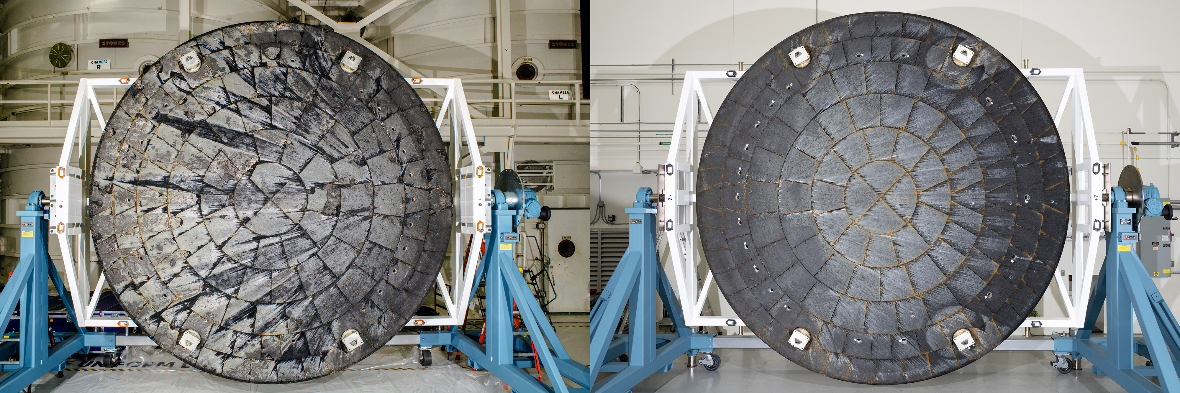
A post‑mission comparison of the Orion spacecraft heat shields from Artemis I (left) and Artemis II (right) are shown after removal from their crew modules. Both heat shields are seen rotated for inspection inside the Operations and Checkout Building at NASA’s Kennedy Space Center in Florida.
NASA

NASA’s Artemis II mission sent four astronauts around the Moon and brought them safely back to Earth, laying a foundation for crewed flights to the Moon’s surface.

Additional engineering data analysis of the Orion spacecraft’s heat shield confirmed initial data showing the heat shield performed as expected.  

In particular, NASA measured whether the thermal protection system effectively safeguarded the crew and Orion systems as the spacecraft reentered Earth’s atmosphere. This test flight was the first time astronauts flew aboard Orion. 

Orion reached a maximum velocity of 39 times the speed of sound and experienced external temperatures exceeding 4,000 degrees Fahrenheit at its peak, all while the four astronauts inside Orion stayed relatively cool with a cabin temperature in the mid-70 degree Fahrenheit range during their return to Earth from the Moon.  

After NASA’s thorough analysis of Artemis I heat shield findings, informed by extensive arc jet material testing at NASA’s Ames Research Center in California’s Silicon Valley, the agency modified Orion’s reentry trajectory for Artemis II by shortening the maximum downrange distance the spacecraft could fly between when it entered Earth’s atmosphere and splashed down in the Pacific Ocean. Analysis prior to the mission showed that limiting downrange distance would limit how long the spacecraft’s heat shield spent in the temperature range at which the Artemis I heat shield phenomenon occurred.  

Shortly after Artemis II splashdown on April 10, 2026, U.S. Navy divers captured underwater imagery of the Orion spacecraft’s heat shield.
US Navy

The spacecraft reentered with precision, entering within only 192 feet of its targeted entry interface, and successfully splashed down only 0.59 miles from the predicted landing site off the coast of San Diego. Initial inspections of the thermal protection system, including diver imagery of the spacecraft’s heat shield taken just after splashdown and further inspections on the recovery ship, found it performed as expected, with a significant reduction in the amount of cracks and char loss as compared to Artemis I.  

Upon the spacecraft’s return to NASA’s Kennedy Space Center in Florida after the Moon mission, thermal protection system experts began additional examination of the heat shield, made of 186 unique blocks of an ablative material called Avcoat. The heat shield was then transported to NASA’s Marshall Space Flight Center in Huntsville, Alabama, where work on sample extraction and internal x-ray scans began in August to provide further engineering insight into the system and behavior of the material.

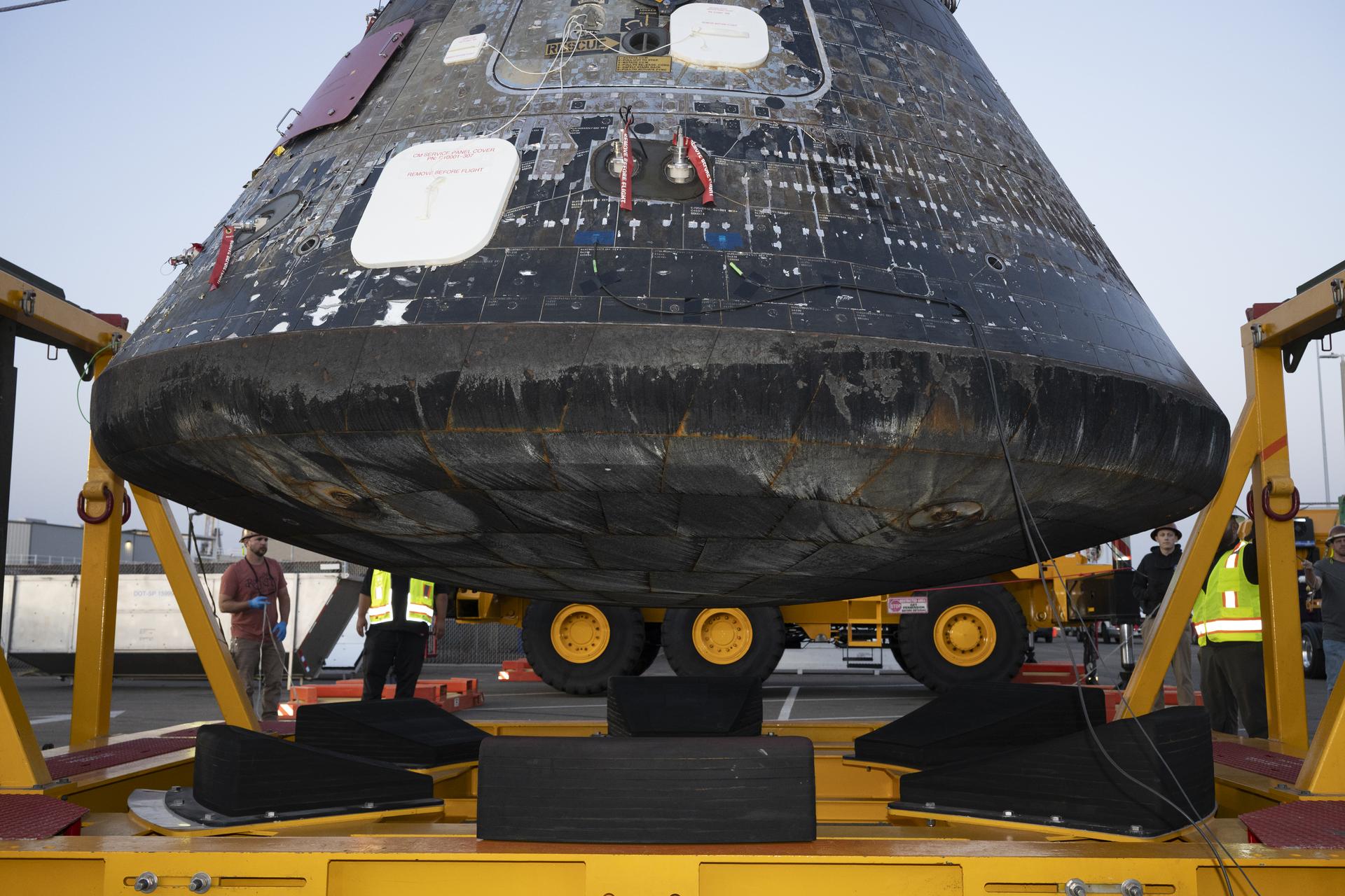
The Artemis II Orion crew module after being offloaded from the well deck of USS John P. Murtha at Naval Base San Diego and lifted from the Orion Recovery Cradle Assembly on April 18, 2026. The gray area, as seen on the edge where the spacecraft’s heat shield and the backshell meet, is from recovery operations.
NASA/Kevin Davis

A thorough post-flight assessment review found that Orion’s aerodynamic and aerothermal performance, including the heat shield and backshell thermal protection system, was in line with engineering predictions based on pre-flight analyses and ground testing. The shorter allowable down range during entry reduced the cracking and char loss experienced on the Artemis II heat shield relative to the Artemis I heat shield by a factor of ten, proving the effectiveness of the trajectory modification. Engineers found only nine spots of char loss of varying sizes on the Artemis II heat shield dish, compared to 103 during Artemis I. 

The analysis also showed that Orion’s robust heat shield design showed consistency from Artemis I to Artemis II, evident by the performance of system features such as the seams between the heat shield Avcoat blocks and the Avcoat surrounding the heat shield compression pad separation bolts. 

Post-flight inspection of Orion’s backshell, the protective cover on the sloped sides of the crew module made up of 1,300 ceramic tiles, showed expected performance across the crew module surface. Visual inspections indicated backshell features designed to seal and protect penetrations such as windows, vents, thrusters, and the side hatch also met expectations, with no signs of overheating observed. 

The team also performed post-flight laser scans of the heat shield surface and is comparing this data to pre-flight measurements to determine material recession, which will then be compared to analysis predictions. Engineers are continuing with heat shield sample extraction at NASA Marshall and subsequent material test and assessment and thermal analysis, to support long-term heat shield development, manufacturing efforts, and data capture. 

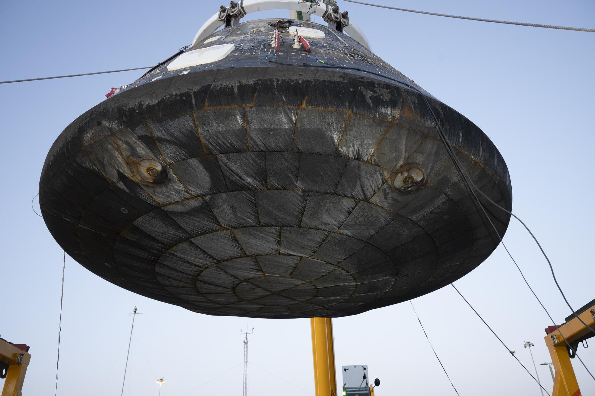
The Artemis II Orion crew module is lifted from its recovery fixture for inspection and engineering imagery after being offloaded from the USS John P. Murtha at Naval Base San Diego on April 18, 2026. The recessed areas, or smaller concentric circles, seen on the heat shield are associated with the separation bolts that connect the crew module with the service module. The larger circular patterns are formed due to compression pad material used within this location of the spacecraft, creating flow disturbances caused by extreme aerodynamic and thermal airflow during reentry. This causes increased heating locally and therefore Avcoat ablator thickness is increased in these areas by design.
NASA/Kevin Davis

Orion’s performance and the team’s analysis on Artemis II reflect system robustness, capability to support crew, and critical insights gathered that will enhance the Artemis III mission and beyond. Following the extensive Artemis I heat shield investigation, upgrades were made to the heat shield design for Artemis III to achieve uniformity and consistent permeability of the Avcoat blocks. Technicians attached the heat shield for the Artemis III Orion crew module at NASA Kennedy in early July, and the Orion crew and service modules were joined at the end of July. The spacecraft has since been successfully powered up for the first time, enabling engineers to check all connection lines between the two modules are working as planned.

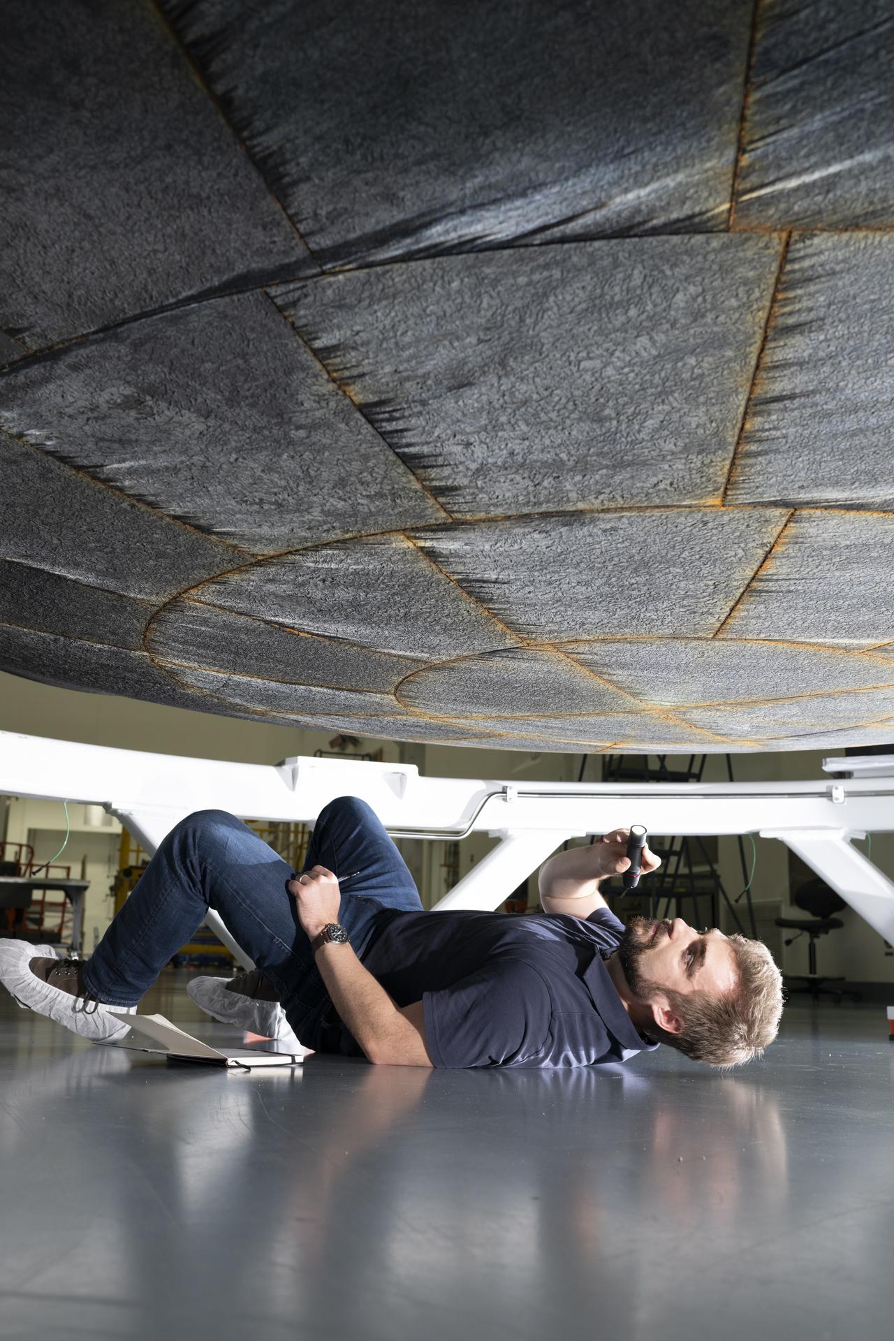
A person lies on the floor of a workshop, holding a flashlight to inspect the underside of a large, circular heat-shield-like structure suspended above them. The individual is positioned on their side beneath the hardware, with tools and equipment visible in the background.
An engineer from NASA’s Ames Research Center inspects the Artemis II Orion heat shield at NASA Kennedy’s Multi-Purpose Payload Facility on April 30, 2026, prior to its removal from the crew module. The orange tint seen between Avcoat tiles is an expected effect of the silicone used to fill the gaps between the blocks. The silicone gap filler contains iron oxide, which gives it a red appearance after enduring reentry. 
NASA/Kevin Davis

NASA continues to advance toward Artemis III as teams ready the Orion spacecraft for next year’s mission in low Earth orbit. NASA will launch the SLS (Space Launch System) rocket and Orion spacecraft with NASA astronauts Randy Bresnik, Frank Rubio, Andre Douglas, and ESA (European Space Agency) Luca Parmitano, to rendezvous with human lander test articles from Blue Origin and SpaceX to demonstrate critical systems and operations needed for future lunar landings, beginning with Artemis IV in 2028.

❌