Reading view

There are new articles available, click to refresh the page.

Analyzing the FScale Instruction in Intel’s 8087 FPU

During his continuing analysis of the architecture and microcode of Intel’s highly influential 8087 floating point unit (FPU) co-processor, [Ken Shirriff] has now arrived at the point where he can put together how the 8087’s microcode implements various x87 instructions. One of these, the FSCALE instruction turned out to be far more complicated than assumed, with one might assume to be a straightforward powers-of-two scaling turning out to entail over 140 micro-instructions and three levels of sub-routine calls just to handle all cases.

The annotated die shot in the heading image shows the functional blocks that are used by this one x87 instruction, to give some kind of idea of what amount of hardware even ‘just’ scaling a floating point number involves.

Much like with the x86’s CISC-style ISA, these 8087 instructions break down into individual steps that involve everything from loading values into registers, performing operations, checking for and handling error conditions as well as stack management. As can be seen in [Ken]’s breakdown of the FSCALE implementation in the 8087 it’s all very logical, taking a high-level instruction and doing all that’s needed for a robust implementation, without bothering the developer with the details.

Of note is that the 8087’s implementations led to the IEEE 754 floating point standard, providing what definitely at the time was one of the most mathematically accurate FPUs that somehow still was financially responsible enough to make it into a relatively affordable PC.


Making an Air-Powered Circular Saw with LEGO

The all-LEGO version barely cuts paper. (Credit: Jamie's Brick Jams, YouTube)
The all-LEGO version barely cuts paper. (Credit: Jamie’s Brick Jams, YouTube)

Although building a table saw out of LEGO is probably not the first thing that comes to mind when you look at those colorful bits of plastic, [Jamie] has been on a bit of a search for more applications of his LEGO-based air-powered motors. Naturally this led to the idea of doing something useful with it, like making a table saw you can actually use for real wood.

Starting off with a basic prototype using only regular LEGO pieces to get the mechanism figured out, [Jamie] then builds this up into said air-powered table saw featuring an actual metal blade. Suffice it to say that this isn’t something that you want your children to do with their LEGO while unsupervised.

The star of the show is of course the air-powered turbine that spins the blade. This is something that [Jamie] has been working on for a while, going through a number of prototypes to figure out a 3D printed geometry for the turbine blade that helps to convert as much of the high-pressure air into rotation.

Along the way it was also discovered that 3D printing saw blades is pretty hard, probably due to the lack of a sharp edge. This is definitely an area where it’s hard to beat a real table saw blade, with the added caveat that anything that’s good at cutting up boards of wood and sausages will just as happy slice through careless primate fingers.

In terms of safety features, the air supply is cut automatically with a sort of dead-man switch that requires you to keep one hand on it while using the final table saw design. There also an auto-feeding system added that tries to guide the board into the saw, but this turned out to be finicky. Suffice it to say that an air compressor and a handful of non-LEGO-approved components created a pretty convincing table saw.

Looking at a TRS-80 12 MB External Hard Drive from 1983

Although hard disks weren’t a common feature yet in many home computers in the 1980s, they were becoming increasingly more affordable. For relative meanings of the word ‘affordable’, naturally. This is illustrated by the 12 MB HDD for the Radio Shack TRS-80 that [Clint] over at LGR recently took a peek at.

Costing a cool $3,495 in 1983 – or $11,932 in 2026 USD – this 12 MB storage wonder used a Tandon TM-603 full-height 5.25″ HDD inside. Lacking a working TRS-80 to try it out with, the video is limited to just a basic powering up and opening up of the unit, but [Clint] will be donating it to a computer museum who can hopefully put it to use again.

The connection to the TRS-80 computer is handled by a ribbon cable, while the HDD has its own built-in power supply, rated at 60 Watt.

On the main board for the external HDD controller there is a Signetics 8X300 microprocessor that forms the brains of what makes it into an external drive for the TRS-80. Despite its age, it still looks brand new inside, so despite the Rifa capacitors in the PSU, [Clint] decided to power it on. This resulted in an auditory experience that’s probably best compared to a very rusty jet engine spinning up after languishing for a decade prior to spooling up for take-off.

Hopefully we’ll find out whether this particular unit and its HDD are still working in 2026.

Trying to Fix a Suspiciously Cheap Enterprise-Grade Network Switch

When you see a listing for an Ethernet switch whose specification list is in effect ‘yes’, with a four-digit price tag when new, and with the seller asking for less than 10% of said $3,000 asking price in an ‘untested’ condition, the only rational thing to do is of course to mash that ‘buy’ button. This is what [This Does Not Compute] did, and created a video about to show what a great investment decision this was.

Naturally this Juniper EX4100-F-12P switch came without power supply brick for its 48VDC input. Figuring out its pin-out and probing said input showed that the voltage rails had been shorted, giving a first clue as to why this switch had been on sale for so very cheap. Bravely hoping that it would be a straightforward fix, the unit was disassembled.

With a 280 Watt power brick, it’s little wonder that the top of the unit is a one massive aluminium heatsink, including a large heatpipe. Also visible on the lid near the power input was a very-bad-news black skid mark.

From that first discovery the news just got worse and worse, with clear signs of water ingression, rust and corrosion, along with the aftermath of a powered circuit meeting such bad corrosion. After some clean-up it’s clear that some components had violently exploded, ripping apart layers of the PCB and likely parts of traces in those inner sections too.

With no schematics available and no other good repair options via Juniper or anywhere else, it seems that unfortunately this gamble turned out to be merely a pile of e-waste and a few bucks worth of scrap metal. Caveat emptor, once more.

Making a Neo Nuvistor Project in 2026

For a little while vacuum tubes and semiconductors were fighting a heated battle for dominance, with bipolar junction transistors and 1959’s RCA Nuvistor both allowing you to build a compact circuit with relatively low power usage and no high voltages. Although we now know that semiconductor technology won out overwhelmingly, that doesn’t mean that you cannot build a brand new Nuvistor board in 2026, as [Eric Schlaepfer] AKA [TubeTimeUS] recently did.
Nuvistors saw their most use in small-signal radio frequency applications, like VHF and UHF, with excellent low-noise characteristics that saw them used until the early 1970s in television sets, radios and oscilloscopes, as well as in space probes like the 1960s US Ranger Moon missions, so by that metric they had a good run.

Nothing so exciting is built in this video, sadly, but alongside a breakdown on how nuvistors work, we do see a discrete 555-style timer built using a gaggle of tetrode nuvistors, giving a pretty good idea of what using them in a project is like. Being a vacuum tube at its core, nuvistors still have the heater element, which is what gives vacuum tubes their reputation for being slow to start working and large current draw.

Despite their drawbacks, nuvistors still have a range of benefits compared to modern-day transistors, including being practically immune to electrostatic discharge (ESD) and electromagnetic interference (EMI) all the way up an EMP that will destroy most semiconductor electronics.

That said, the somewhat limited 8-nuvistor implementation of the 555 had to get a few extra pins for the heater supply, which burns up about 7.5 Watt just to allow the circuit to function. Terming it the ‘hollow-state 555 timer’, it works effectively just like any semiconductor 555, just with that extra power cost and of course no significant prospect of making it smaller, barring a semiconductor evolution as with the pixels-sized CRTs in the SED and FED type displays.

We covered the nuvistor before, including a great reference on this device, and its history that was much longer than people often assume today, as well as the vacuum tubes we use every day in for example our microwaves.

Changing Nozzle Internal Geometry to Increase FDM Flowrate

As FDM printers keep getting faster, we are forced to deal with a range of bottlenecks, all of which conspire to hold us back from another Benchie world record. A major physical limitation is that of flowrate, as the hotend has to be able to melt the filament that enters the nozzle before it departs said nozzle. One attempt to make a high-flow nozzle involves splitting the material path into three winding sections, which theoretically should help said flowrate. Recently [Thomas Sanladerer] took a poke at this and other types of nozzle with SLS-printed nozzles.

These printed parts still needed some finishing on the lathe, including drilling the 0.4 mm nozzle hole. The finished nozzles feature a variety of internal geometries, including the aforementioned triple-path, as well as many with various intrusions that seek to maximize the contact area.

Using a Prusa Core One these nozzles were subsequently tested to see what print quality they produced at high flow rates. A special test rig to test the nozzle pressure was also used to further characterize them, as this indicates at which flowrate the nozzle begins to struggle. Among these the Fuge design did the best, though with the big asterisk that these nozzles were printed in MS1, which is in effect tool steel and thus not great for being nozzles.

Creating a Custom Hinge for a Motorbike’s Fuel Access Panel

A fun part of modifying something like a motorbike is that you sometimes have to come up with creative solutions to basic questions, like how you can still access the fuel tank’s cap after extending it forward. In the case of [KRTframework] this meant that the fuel cap was now underneath the bodywork, requiring a suitable way to access it. Of course, this meant making a hidden access panel with a custom hinge, to not break the bike’s clean lines.

To make the process as easy as possible, a 3D scanner was used to get detailed measurements on what the new bodywork would look like. Using these the new bodywork was created, including what would be the hidden access panel, yet finding a suitable hinge mechanism wasn’t easy. This is where this custom design was created, with detailed assembly covered in the video.

To bridge the gap between the opening and the fuel tank a part was 3D-printed that also contains the simple push-to-open latch mechanism. Of course, in the comment section people sounded off on this, feeling that it would be far too easy to accidentally open the panel.

The hinge seems to be well-received at least, with it having to fit within the available space, while also providing good access to the fuel cap when opened, meaning quite a lot of travel.

Decoding the NEC V20 Microcode ROM

The NEC V20 is an Intel 8088-compatible processor that features the same use of microcode, though with its own characteristics. This makes it important to use this same microcode if your goal is to create a cycle-accurate emulator of this processor, as [GloriousCow]’s goal is. Cue decoding the microcode ROM in a die shot of this CPU, in order to create a usable ROM image.

As with any fabricated ROM you can technically do it by hand, the ROM section in the die shot contained 29,928 bits which even at a pretty zippy pace would take up a considerable amount of time to parse. Here you can divide-and-conquer by handing parts of the ROM off to good friends, or you can use automation and some machine vision and theoretically get an answer as soon as you have finished writing and testing the tool.

Close-up of some of the microcode bits.

Although [Travis Goodspeed]’s MaskRomTool exists exactly to automate bit detection, it was found that there wasn’t enough contrast in the die shot for it to work reliably. What it did provide were the locations of the bits and from it 42×42 pixel PNG files of each bit.

Next a convolutional neural network (CNN) was trained to determine the difference between a 0 and 1 bit. This still took the manual classifying of 1,000 images, but seemed to work fairly well. Although some bits were marked as ambiguous, it was easy enough to use Mark 1 eyeballs to run a classification on these handful of images than to tweak the CNN model.

With this microcode in hand it was then possible to match it against the V20’s internal architecture to fully determine what each part does. Although not quite finished yet, there’s a GitHub repository containing the progress so far.

The V20’s microcode has been the focal point of much legal fighting back when NEC and Intel were still duking it out in how far one could make a CPU compatible with that of a competitor.

Fixing a 1990s LEGO Electric Train Speed Regulator

Before LEGO train sets moved to battery-powered locomotives with plastic rails, all of them worked pretty much like any other train set of the era. This meant metal rails that the locomotive’s wheels would use to pick up power from and a central controller that would inject said power and also regulate the train’s speed and direction. The LEGO 2868b Electric Train Speed Regulator is one such example, and [Nonsense Wars] recently had one under the knife to repair it.

The single PCB inside is quite straightforward, with the 9-12 VAC supply input from an external power adapter, and a variable voltage regulator that sees its target voltage switched by a bank of resistors.

It are these resistors that the big yellow control switches between when you operate it, changing the output voltage and also output polarity you cross the midway point. Effectively this means that there is just one non-passive component on the PCB, in the form of the TO-220 package strapped to the big heatsink.

In this particular unit it was found to be a Fairchild KA317, which is for all intents and purposes here the same as an LM317T. One quick swap later and this controller was back in business like it was 1995.

Compared to the engineering crammed into a modern “smart brick”, things really have come quite a ways in the world of LEGO.

Disassembling a Mini Air Blower to Make RC Airplanes

As a certified RC airplane fan, the [RCMakerLab] on YouTube found themselves looking at one of those nifty mini air blowers that provide an alternative to a compressor and canned air for dusting and other high-volume, high-pressure air-related tasks.

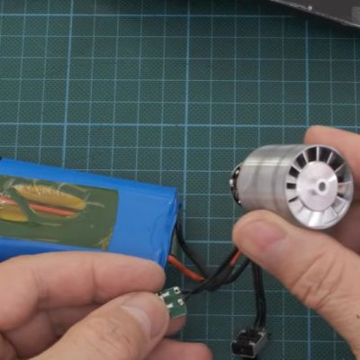
Inside these quite affordable units is a ducted fan (EDF) that can produce fairly high levels of airflow to get to every last dust bunny hiding on a PCB or inside a keyboard, raising the question of whether you could use these to fly a model airplane with.

As can be seen in the torn down unit, there isn’t a lot to these air blowers, with the ESC bolted onto the EDF and only the speed regulator and on/off switch being external controls. This would make it very easy to integrate into an airplane, but leaves the question of whether it can generate enough thrust to make it worth the effort.

Using a custom rig, it was shown to generate up to 110 grams of thrust with a current of 16.5 A, which would at least go a long way to carrying its own battery pack. In order to create an airplane with it, probably two of these motors are needed. There’s also the potential of reducing weight by changing the ESC and such, making reusing these little EDFs from any discarded or broken mini air blowers at least worth a shot.

At the very least, it seems like it has a better shot of working than a plane powered by an electric leaf blower.

How Bats Prevent Doppler Acoustic Interference

https://commons.wikimedia.org/wiki/File:Bat(20070605).jpg
Lesser horseshoe bat. (Credit: Lylambda, Wikimedia)

As great as echolocation is, things can get rather messy once it’s not just you chirping away, but also hundreds of your buddies in roughly the same area. This is the scenario that the typical colonies of bats have to deal with. In a recent study by [Haruhito Matsumoto] et al. in Journal of Comparative Physiology they investigated how colonies of greater Japanese horseshoe bats deal with this issue.

Echolocation in animals can use a variety of methods, including frequency modulation (FM, varying the pitch) or constant frequency (CF), with both having their uses during hunting as well as obstacle avoidance. One big advantage of CF is that it can be used for Doppler shift, giving very precise information about location and velocity of objects in the environment, but if used in a busy colony the acoustic interference would effectively render them blind.

What researchers have found is that the CF component frequencies differ per bat colonies, with the mixing of wild-caught and resident horseshoe bats in this experiment showing them adjusting the dominant second harmonic (CF2) to match, with bats using a lower frequency CF2 adjusting it upwards. In this way frequency convergence is used as a strategy to avoid acoustic interference using a so-called ‘silent spectral window’.

As this spectral window for effective Doppler tracking is found above the CF2 frequency, it therefore makes sense that the bats at a lower CF2 harmonic would adjust their CF upwards to match that of their neighbors. Although more research is required to fully confirm these findings, it sheds some more light on the use of echolocation by these amazing flying mammals.

Kelvin–Helmholtz Instabilities Found to Drive Plasma Mixing on the Sun

As easy as the Sun is to observe, it’s simultaneously very hard to study due to how extreme the conditions are, even on the surface of a rather unassuming star. One of these study topics is the interaction between the Sun’s plasma and magnetic field, as this drives much of the dynamism of the Sun’s surface layer (i.e., the photosphere). Recent observations by the 4-meter solar telescope in Hawaii have now led to interesting new findings, as detailed in a paper in Nature by [David Kuridze] et al.

Despite popular portrayal, this photosphere is not a boiling liquid, but rather pockets of plasma at various temperatures. The plasma moves within the magnetic field and convective movements that create the ‘boiling’ pattern, which gives the illusion of a boiling liquid surface.

Within this photosphere, [Kuridze] et al. were able to observe Kelvin-Helmholtz instabilities, which are fluid instabilities caused by velocity shearing in either a continuous fluid or due to a velocity difference between two fluids. This is also observed in clouds in Earth’s atmosphere, where they cause the billowing effect, somewhat similar to watching a boiling liquid.

In a MURaM simulation (see heading image), these findings were confirmed, showing how these instabilities drive the transport of plasma in the Sun’s photosphere.

Comparing PETG and PCTG Filaments

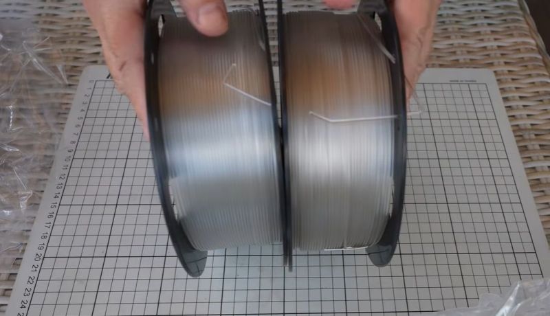
The average 3D printer owner knows a few types of filaments – PLA, ABS, somewhere in the middle, PETG.  PCTG is another option that can be confusingly similar to PETG. Recently, [Igor Gaspar] of [My Tech Fun] took a poke at both types. He obtained both PETG and PCTG transparent filaments from the same manufacturer to compare them directly.

As we recently detailed in an article on PET polyesters, PETG is glycol-modified PET, meaning that some of the glycol monomers are replaced by CHDM monomers to create a more flexible and robust material. PCTG is very similar to PETG, except that more than half of the glycol monomers are replaced rather than less than half. This creates a PET-type material that has distinct physical properties from PETG, which might be desirable for some applications.

PCTG is more ductile due to the addition of more CHDM, but also requires higher temperatures to print, closer to ASA presets. During testing, it’s obvious that PCTG is indeed much more flexible, making it potentially a good choice for springs and compliant mechanisms. PCTG is also highly impact-resistant, unlike PETG, and resists higher temperatures much better.

Overall, other than the higher printing temperatures, PCTG seems like a solid option for more extreme environments, potentially as an alternative to ASA and similar filaments.

How Charged Water Drops Induce Corrosion

Generally, we do not look at the gentle patter of raindrops on a surface with much concern, but according to a study by [Zhongyuan Ni] et al. in Nature, we should probably regard these droplets with a little scrutiny for their corrosion potential. What they found is that these drops can gather a significant electric potential as they gently slide down a surface, with over 1 kV measured. By first having droplets charge up on an insulating surface before hitting a target metal surface, they were able to induce significant corrosion.

Despite the target metal surface being coated with a protective layer, these charged droplets managed to gradually break down the coating, exposing the bare metal. In this example, a Teflon coating was used, with water droplets containing a small amount of dissolved sodium chloride to simulate natural raindrops.

It was postulated that this causes dielectric breakdown of the insulating protective coating, as the charged water drop acts as one electrode and the — often grounded — metal surface as another electrode. Subsequent investigations on the samples showed that this appears to be indeed the case.

A potential defense here would be to discharge any water before it can reach sensitive surfaces, but it’s not a straightforward problem to solve. As noted in the study’s conclusion, charged droplets can also be generated in clouds and waves, in addition to the insulating materials demonstrated in the study. It’s also a phenomenon that can cause issues anywhere charged droplets occur, such as in a wide range of industrial processes.

If you’re interested in the electrical generating properties of falling water, check out Lord Kelvin’s Generator! Hackaday’s own [Steven Dufresne] explored this phenomenon a few years back.

Saturn’s South Pole is Apparently Decagon-Shaped

Saturn's north pole captured by Cassini in 2013. (Credit: NASA/JPL-Caltech/SSI/CICLOPS/Kevin M. Gill)
Saturn’s north pole captured by Cassini in 2013. (Credit: NASA/JPL-Caltech/SSI/CICLOPS/Kevin M. Gill)

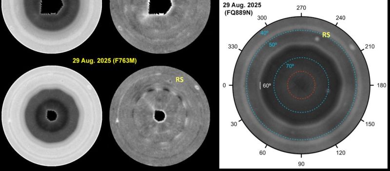
Although some would argue that the hexagon is the bestagon, astronomers have discovered that Saturn appears to favor the ten-sided decagon on its south pole. This comes as its south pole has recently been confirmed to show a pattern that’s oddly ten-sided, per a recent research article by [Agustín Sánchez-Lavega] et al. in Science Advances.

Because Saturn is a gas giant, this naturally isn’t some gigantic planet-sized rock formation, but rather an interesting wave phenomenon in this massive gas bubble. The hexagon shape on its north pole had been known about for a while already, so it is perhaps not too surprising to find something similar on its south pole.

These shapes are generally the result of standing waves within a polar vortex, through the interaction of waves in Saturn’s atmosphere. For the north pole hexagon, the formation is driven by an intense eastward jet, but no similar wave had been reported for the planet’s south pole.

While in this paper a decagon shape is identified based on multiple observations, they postulate that it’s due to a meandering wave in the area rather than a jet as at the other pole. This clearly doesn’t make this wave pattern as obvious as the one at the north pole, but it provides another fascinating insight into fluid dynamics scaled up to a planetary gas giant.

Can AI Now Design PCBs That Just Work?

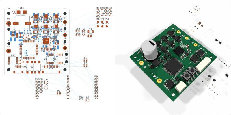
With the recent release of its GPT-6 Astra model, OpenAI explicitly pushed the claim that it is capable of designing complete circuit boards in KiCad, starting from a provided schematic and outputting a fully routed PCB that theoretically could be sent off to be manufactured. This of course raises the question whether this is just a nifty party trick that works under strictly controlled conditions like most auto-routing tools, or whether there’s more to it. In a recent [EEBench] blog post, OpenAI’s claims are put to the test.

Back in 2024, we looked at how LLMs handle circuit board design, starting with the schematic. The conclusion was that you might as well just do it all by hand. Tracking progress here, [EEBench] is an electrical engineering agent benchmark that tests how effective these so-called AI agents are at performing useful hardware engineering work. As their methodology already makes clear, creating a populated and routed PCB from a schematic is just one step of many.

Consequently, GPT-6 Astra scores 69.3% (+/- 10%) on their benchmark, roughly in the same ballpark as Claude Opus 5, albeit cheaper and faster. It should be noted that [EEBench] is run by the developers behind Atopile, which is a code-based system for creating PCBs in KiCad with a strong focus on use by such AI agents.

Despite this, the blog post makes it clear that there is still a long way to go before hardware engineers can receive their pink slips and take up another profession. After all, while vibe-coding a quick prototype PCB can be a nice shortcut, for a one-off project PCB, most boards are expected to handle all the edge cases, be fully validated by multiple independent engineers, and have passed stringent testing before committing to a production run.

(Top image: from OpenAI GPT-6 Astra KiCad video)

Pixel Watch 5 Demonstrates Good Repairability

Although we often find ourselves drowning in a seemingly unending sea of portable devices that are effectively e-waste once an internal component gives out, it’s good to remind ourselves that there are a few examples out there by large brands that manage to tick all the fancy feature boxes, while still being very much repairable. Case in point the Pixel Watch 5, a smart watch which much like its predecessor gets a 9/10 on [iFixit]’s repairability score.

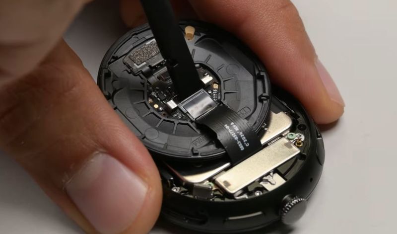
No heat gun required, just undo the latch on the side of the watch. (Credit: iFixit, YouTube)
No heat gun required, just undo the latch on the side of the watch.

Despite featuring an IP68 rating, opening it is as easy as taking out a few screws to release its latch. This allows the back to swing open, with not a drop of glue in sight, just an O-ring gasket that keeps moisture out and can be reused many times. Digging into the guts, there are color-coded screws that guide one’s hand as the very modular design is taken apart in a matter of minutes.

Being able to simply unlatch the back, and also easily obtain spare parts are two aspects that are a very welcome sight indeed. Although it’s much easier to just glue everything together, something like this latch-and-gasket approach is something that we hope that more manufacturers will copy for these small devices.

It’s potentially also an idea for one’s next DIY smart watch project, as tempting as reaching for that tube of glue may seem.

Fixing an Expensive Seagate LaCie Hard Drive Array

After the [Slow Mo Guys] acquired a 168 TB Seagate LaCie Thunderbolt 3-based RAID storage system back in 2019 to store their video footage, they were obviously slightly miffed when suddenly it would just refuse to power up. Naturally the device was now out of warranty, the product itself no longer produced and Seagate support was less than supportive, ergo they sent the device to [Mend it Mark] for an attempted repair.

At first inspection the device appeared to be basically unresponsive, with none of the four fans running and no signs of life other than a few lit LEDs on the main PCB after supplying power to it. After full disassembly and with no repair guide or schematics to go by [Mark] had to start from basics, first diagnosing whether all the power rails were turning on, which they weren’t.

Eventually this led to the NXP LPC11U6x-series MCU which acts as the main power management and monitoring chip in the system. [Mark] deduced that this MCU wasn’t turning on all the power rails because it was waiting for a signal from the fan controllers on the SATA backplane. With the MCU sending the right signals here, and the fans all working when directly supplied with power, ultimately it turned out that a single SI2319 or similar P-channel MOSFET in SOT-23 package near one of the fan connectors had gone faulty.

Replacing this one MOSFET seems to have fixed the RAID array, with it now happily powering up, although the real test will be once the [Slow Mo Guys] start shoving the HDDs back into it. Assuming that this was the sole fault in the system, then it was a very cheap fix in terms of materials. It’s a real shame that repair guides or schematics aren’t made available for devices like this, even if just after they stop being produced.

Making a Pole Balance Itself With Propellers

A fun trick with a pole is to try to balance it so that it can stand on one end. This can be done in a few ways, such as by exerting a force on either end to counterbalance any force that threatens to make it fall over. The approach that [Peter Ryseck] chose was to cobble together what is effectively a flying drone for on top of a standing pole, without cheating such as by simply lifting it off the ground.

Getting to the point where the drone could react quickly enough to changes in the pole’s orientation was the hardest part, as the quieter, larger propellers also have a lot more inertia. This ruled out using 10″ blades, while triple 5″ blades seemed to work well enough. For the avionics a standard quadcopter control board and software is used, with the programming such that it’ll react appropriately without causing additional instabilities.

Naturally making this work took some trial and error, with issues like oscillations plaguing the system. One unexpected problem was that the pole – taken from a pool fishing net – was flexible enough to add its own instabilities to the system. In the video all these issues and their solutions are explained in detail, along with the ultimate result. One very neat solution here for example is to have the pole lean into the wind, which is a more stable configuration than insisting on having the pole be at a perfect ninety degrees with the ground.

Repairing Traces on a Delidded Pentium III CPU Gone Wrong

Delidding a CPU involves removing the integrated heat spreader (IHS) that’s put over the bare die and the substrate that it is mounted on. The reason for this is usually to improve cooling performance, as the IHS is effectively a small heatsink between the die and the large heatsink, adding more problematic thermal interfaces. If delidding is done improperly it can cause severe damage to the substrate, as in the case of a very nice 1.3 GHz Tualatin Pentium III CPU that [Bits und Bolts] got in an eBay lot with nasty delidding damage.

With the delidding enthusiast presumably having used brute force and ignorance combined with a prying implement, around a dozen of tiny traces on the substrate got severed, requiring tedious trace repair to fix. After confirming that with the severed traces the CPU is indeed busted, enough of the soldermask is removed to make a repair.

Any traces that were still good got covered with soldermask, while for the remainders the thinnest available copper wire was used to create new traces. Although very much doable with a good microscope and a steady hand, this is definitely one of those things that’s much easier to prevent than to fix.

With IHSes having become standard on CPUs, delidding continues to this day, with increasing risks of severed traces and ripped-off capacitors should it go wrong. Although those newer CPU substrates are probably not repairable, repairing these older CPUs instead of tossing them as e-waste seems plausible at least.

❌