Reading view

There are new articles available, click to refresh the page.

Hackaday Europe 2026: Outdoors with Robots

Erin Kennedy has been building robots for over a decade now, with a focus on smaller bots that interact with, or maybe even clean up, the outdoor environment. Still other bots are made to interact with people, and when the people are outside in the park, that’s where your robot needs to go.

Whatever the reason, Erin’s talk at Hackaday Europe 2026 is an invitation to take your projects out into the outdoors. But the great wide world outside of your lab is not necessarily the most friendly place for a little bot, and the other half of this talk is about practical design tips and lessons learned to help it survive.

Environments

She structures the talk around different environments, which gives her an opportunity to focus on her bot cleaning up plastic trash on the beach, but also to point out the absolute horrors that sand can work on robot motors. She goes through a number of strategies for dealing with this, including going slow, keeping the motors as high up as you can, and designing the body of the robot to be full of holes and shed sand.

Taking to the water, she demos Otter Force One, which aims to capture invasive sea urchins. But underwater means under pressure, and she gives us some good tips on how to get the cables out while keeping the water in – double-o-ring cable glands potted with marine epoxy. I especially love the Nalgene-bottle-on-a-string with a radio that can be deployed to help retrieval. Her lessons-learned section is as deep as it is understated, including underwater hazards from low visibility to accumulated silt messing up your presumed center of gravity. Over the long term, rubber leaks and barnacles accumulate. Double seals, durable hooks, tether ropes, and bright colors are your friends. Underwater bots have it hard.

Erin’s air-inspired bots are the wildest. Some are just whimsical, like the flappy square bird, or beautiful like the butterfly bots. But her Atmosphinder bot uses the wind for actual propulsion. It’s a rolling wheel with sails that aims to explore long distances on Mars. Whether it’s going to get there or not, it’s got a bunch of great design elements for anything you have that’s going to have to roll. “Magic toboggans” make great plastic sails. But beware, while you can turn off a motor, you can’t turn off the wind. Be prepared to stake your bot down before or after its mission.

Experiences

Whatever the environmental challenges of taking your bot outside, it’s the non-laboratory environment that’s the most challenging, and rewarding. Erin tells the story of when a bird settled down in the shade cast by Bowie, or when the wind blew all of the Aruco markers away. But people and animals are just as delightful and unpredictable as the weather, and that’s an extra level of adventure. If you’re going far, bring hydration for the humans and spare batteries for the bots. Rolling with the changes seems to be the key to having a good time outside with your bots.

And of course, bringing your robot outside is a great opportunity to share what you’ve been working on with the offline world. We absolutely love the mission: normalizing robot hacks among the general public by hanging out with your bot in the park is right up our alley. She has had tremendous success with random encounters – folks just coming up and asking about what it’s doing. Making your bot seem friendly and/or beautiful seems to go a long way here. Don’t neglect the aesthetics.

Take Your Bot Outside

We left Erin’s talk absolutely inspired to build something that can make it through the rough environment that lies just outside our basement. It reminded us of our old days experimenting around with BEAM robotics, another bio-inspired practice aimed at the outdoors. With 3D printable parts and cheap geared motors, you don’t even have to break the bank to build your own Mars neighborhood rover. Watch this talk and get inspired!

COSMAC Elf Turns 50

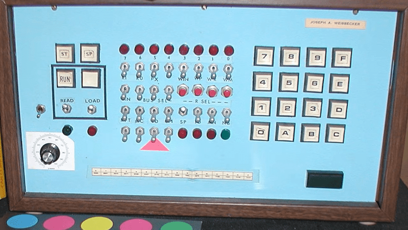
If you were interested in computers in the early 1970s, you struggled to get time on real computers since owning your own was all but impossible. In the middle of the decade, though, you could get a few computers: the Mark VIII, the Altair, the Apple I, and several others. Those were still pretty expensive, though. But in late 1976, an article in Popular Electronics said you could build a “powerful, expandable” computer for $80. The article in question was by [Joseph Weisbecker], who, unknown to most of us at the time, was actually the RCA employee behind the CPU — an RCA 1802. [Tech Time Traveler] takes a close look at the spunky little computer’s history in the video you can see below.

The 1802 was actually the second generation of the CPU, but the first that was all-in-one chip. [Weisbecker] started building the CPU as a personal project. He’d been a hacker even in high school, building relay-based tic-tac-toe games, among other things.

The first incarnation in his lab was “Fred,” with 100 TTL chips, and his idea was to have the computer be at least partially used as a video game — an interesting point, with Pong being very popular at the time.

The video covers a lot of history, but from a hacker’s point of view, the CPU was both amazing and limited. In a day when the 8080 and Z80 were kings, the 1802 had built-in DMA. This allowed a cheap companion video display that simply read bytes from memory and pushed them out to a TV.

Another neat feature was that the device had 16-bit registers and, even more interesting, 16 of them. On the one hand, any register could be, for example, the program counter or a memory index register. But on the other hand, there was no direct stack for doing calls and returns. The idea was that you’d use different registers for different subroutines, which was fine and efficient for very simple programs but not for the general case. One thing all 1802 programmers knew about was SCRT, the “standard call return technique” routines in the 1802 manual. But, as you might expect, this made calls and returns expensive.

There’s more that you’ll see in the video. People still build 1802-based computers and, of course, there are plenty of simulators, including ours. One thing you’ll notice is that the instruction set is very regular. Even if you didn’t know, you might guess that one guy designed the architecture.

Playing Snake with a Pneumatic Display

A man’s hands are shown holding a video game controller. A cable runs to a box with an orange front surface, which has a series of divots arranged in a points on a grid. These divots form a vertical line, with one other divot to the right of and below the line.

[soiboi soft]’s vacuum-driven dot matrix display is part suction gripper, part touchscreen, and altogether impressive. Its display capabilities are entirely shadow-based, with each pixel being made of a cavity behind a flexible silicone sheet; when the display’s microfluidic logic circuitry activates a pixel, a vacuum pump pulls the sheet inwards, creating a visible hollow.

As in previous iterations, the display’s control circuitry is built around a pneumatic “transistor”, which allows an air channel to be opened or closed by applying vacuum to a control channel. As a first test, [soiboi soft] built a 16-pixel dot matrix display. Eight control channels – four row and four column channels – are multiplexed to individually control each pixel. The transistors act like one-way valves, so the pixels hold their state, even when pressed in by hand; simply add some circuitry to read a pixel’s state, and it would be a fully-functioning touchscreen. The supporting pneumatics also got an upgrade; the solenoid valves now cleanly mount to the back of the board, and the vacuum pump connects via a Luer lock adapter.

The 3D printing used to make certain parts and silicone molds caused issues when scaling up to a 64-pixel display, however. The parts were warping, destroying the seal necessary to keep pixels “on”. To straighten them out, [soiboi soft] pressed the printed part against a flat glass build plate in a vacuum bag and annealed it at 60 Celsius for several hours. This worked quite well, particularly when slightly raised rings were printed around the area to be sealed. Once all these bugs were worked out, the display was clear and decently responsive. [soiboi soft] was able to display letters, numerals, and animations, and even able to play Pong and Snake. It won’t be setting any refresh rate records, but it was nevertheless fully usable.

For another approach to playing Snake with microfluidics, check out this project. If printing molds and casting silicone seems too fiddly, there are always other ways to make microfluidic circuits.

Blow Those Pyros With A Telephone!

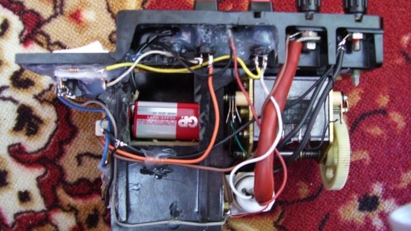
A pyrotechnic charge is set off by passing a high voltage through a filament within it, melting the filament and igniting the charge. We could think of a variety of circuits that could do this, but perhaps we wouldn’t have come up with [Michał Słomkowski]’s solution. He’s used the ringer crank generator from an old military field telephone. It’s an old project he’s shared with us due to its recent republishing on his website.

The basic principle is simple enough, winding the generator charges a capacitor bank through a bridge rectifier. Then a thyristor is used as the trigger device, dumping the contents of the capacitor into the filament. But the full circuit has a couple of refinements. There’s a charge indicator circuit using a couple of Zener diodes and an LED, and a filament tester which passes a non-triggering current through the filament from a 9 volt battery. We like the use of an over-the-top high-current thyristor, no doubt what he had in his junk box.

Perhaps it’s a symbol of how far technology has moved, that today it’s surprisingly rare to find a bridge rectifier or a thyristor, and building this device today would involve a microcontroller and probably an AliExpress inverter module as a matter of course.

Meanwhile, should field telephones interest you, we’ve been there before.

How the Grid’s Harmonic Filters Keep the Power Clean

A fun way to think about a national electrical grid is as a massively upscaled electrical circuit, one in which you have multiple power supplies injecting AC power, with various bits and bobs involving resistors, inductors and capacitors in between working to synchronize and clean-up this power before it gets to the end users. Recently [Jordan Taylor], also known as [The Electric Brit] took a look at the grid’s harmonic filters that do a lot of this sinewave scrubbing after the HVDC to AC conversion.

Using a UK-based line-commutated converter (LCC) HVDC converter station as a physical example [Jordan] takes us through the elements of this harmonic filter, what it is, what it does and why it’s a necessity. The design considerations with components at this immense scale are also covered, along with the types of filters possible.

The Cliff’s Notes version is that following the conversion step from said HVDC there are harmonics introduced in the AC, not unlike in a much lower-voltage converter. This results in a noisy sinewave that can potentially cause harm to AC-powered devices, not to mention cause heating and other losses along the way. The answer is naturally to add an LC-filter, just on a slightly larger scale than for consumer electronics.

Also noted by [Jordan] is the nice synergy of these harmonic filters when it comes to absorbing and generating reactive power on the AC grid, due to their massive capacitors and inductors. This helps to dampen oscillations on the grid and thus further contributing to its stability.

❌