[Hans Scharler] came into a neat find recently—the playfield from a 1970s Atari Superman game. It’s the sort of thing that’s too nice to throw away, but isn’t really enough to reassemble into a viable full machine without a great deal of effort. Thus, [Hans] went a different route—turning it into a beautiful piece of wall art.
The first step of the build was to collect missing parts; in particular, all the plastic inserts for the playfield that had been lost at some point. Everything was cleaned up and mounted, along with some modified flippers to complete the look. Custom pop bumpers were 3D printed to act as LED-lit light guides rather than as functional pinball components. [Hans] then set about dotting the board with plenty of WS2811 addressable LEDs in a bullet form factor. Everything was placed under the command of a WLED controller, and it’s synced up to [Hans’s] CheerLights MQTT server to boot. More build details are available on the Pinside post for those eager for a deeper dive.
If you run a large meteorology bureau, then you probably have access to a wonderful weather radar for scrying the heavens. The rest of us aren’t so lucky. If you find yourself bereft of such hardware, though, you could build your own, taking your lead from [Koakno]’s fine example.
The build uses a satellite dome salvaged from an old RV that [Koakno] scored for just $5. Specifically, a Winegard Carryout Anser GM-5000. The motorized parabolic dish was designed to track TV satellites, but here it’s been repurposed into a scanning radar antenna for X-band signals. It’s paired with a cheap SDR—you can use several on the market—which injects an 850 MHz signal, which is up-converted to 10.4 GHz by the low-noise block (LNB) in the GM-5000 and sprayed out towards the weather.
Echoes come back from rain, hail, and debris, and get down-converted by the LNB back into an 850 MHz signal that the SDR can capture. The echoes are then plotted on a Plan Position Indicator (PPI) display, showing what’s going on in the atmosphere around the dome. [Koakno] reckons detection ranges span out to 40 km for things like heavy rain, while a supercell hail core could be spotted at up to 60 km in the right conditions.
It’s worth noting something important, though. [Koakno] explains that this system is currently in violation of FCC regulations (and probably others around the world), and shouldn’t be used without the proper licenses to access given spectrum. It’s a useful study of how to build a weather radar, but perhaps not something you can just wire together and fire up without getting in a spot of bother.
If you’re a die-hard tornado chaser or you’ve just always longed to stare meaningfully at a PPI display, this could be the build for you. We’ve featured other DIY radars before, too. We’d also like to see yours, so when it’s done and written up, fire us a note on the tipsline!
Radios were once big complicated appliances, full of warm valves and paper-wrapped capacitors, all humming and glowing to capture signals from the aether and spit them out of a speaker. Every component was chosen to build the radio to suit a particular purpose.
These days, we have altogether fancier technology that lets us build radios that can be reconfigured on the fly; software-defined radios, if you will. [Anders Nielsen] has been exploring how to build a high-performance SDR recently, and came to Hackaday Europe 2026 to tell us all about it.
SDR Killed The Radio Star
[Anders] is a bit of hacker type. He’s a firmware developer for satellites in his day job, and he’s always a fan of tinkering with old integrated circuits and trying to build new and interesting things with them. Recently, though, his personal project has been developing a software-defined radio on a budget of under $50.
Now, [Anders] could have simply bought a cheap SDR off the shelf; he himself calls out the Zync/AD9363 platform as one particular example. However, he notes that many available options hide a lot of the signal chain and come at a certain price. He wanted to build something cheap and transparent for experimentation’s sake.
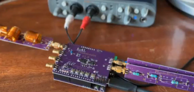
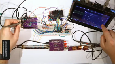
Early testing just relied on using a soundcard as an ADC to verify things were working.
The ultimate goal was to build an affordable SDR with a bandwidth up to 20 MHz. To reach this in his build, [Anders] picked a TLV3253 to serve in the quadrature sampling role, for its quick switching speed and low on resistance. It’s paired with a Silicon Labs 5351 which serves as the local oscillator. It’s possible to phase offset two clocks from the same phased-locked loop, allowing the generation of multiple clocks of the same frequency but offset by 90 degrees. An ADA4891 op-amp is used as a buffer between the capacitors of the quadrature sampling detector and the analog-to-digital converter itself. Testing began with a very simple ADC—a soundcard, capable of up to 44.1 KHz of bandwidth. Later, [Anders] stepped up to using an STM32 with a dual ADC for 200 KHz bandwidth. Eventually, though, the build was upgraded to the HT9201 dual 20 MHz 10-bit ADC. Getting the signal into the computer is handled with an FX2LP clone, which can stream data over USB 2.0 at high speed. With a nominal 480 megabits on offer, the choice is to run with 20 MHz of bandwidth at 8-bit samples, or 10 MHz of bandwidth with 10-bit samples.
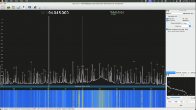
[Anders] laced together the build, piece by piece. It’s less integrated than some off the shelf solutions out there, but it’s cheaper, too.The live demo showed the SDR pulling in the whole FM broadcast spectrum at once—a neat way to put the rig through its paces.
There were some challenges that cropped up along the way. Getting a flat analog frequency response proved difficult, with [Anders] noting this requires good attention to PCB layout, as well as things like amplification and filtering. There were also difficulties with clock jitter and synchronization, and bandwidth limitations in the front end. However, none of this stopped [Anders] from giving a live demo of the SDR in action during the talk. He showed off his rig pulling in the whole FM broadcast band, all at once. The crunchy sound of a commercial station coming in live was an excellent way to show that the SDR indeed was functioning as intended. [Anders] also used this as an opportunity to show some tricks to identifying and dealing with mirror signals when they pop up. There’s plenty that [Anders] wants to do with this project going forward, too. He notes that a wideband front-end mixer is on the cards, as well as a low-noise amplifier and an improved filtering strategy, all of which should improve flexibility and performance.
It’s not the greatest SDR out there, but it is one that taught [Anders] a great deal, and could do the same for others eager to tinker in this field. Sometimes the best way to learn about something is to go and build one for yourself, and this project proves that as so many have done before. It’s exactly what we love to see at a Hackaday conference!
[Do As I Do] had a simple task to complete. A couple of small parts needed to be duplicated in some quantity, with good dimensional accuracy and surface finish. There are a number of ways you might go about this, particularly if you have the original tooling or a machine shop on hand. In this case, however, the plan was to duplicate the parts with silicone molds.
The first step, naturally, was to produce the silicone molds. Doing this involved some craft supplies, with glossy paper and hot glue used to create a vessel for casting silicone around the original parts. The silicone itself was mixed carefully and poured into the vessels, and soon enough [Do As I Do] had a pair of negative molds that could be used to produce duplicates of the original. The original parts were removed, and the silicone molds were filled with resin over and over again to make as many duplicates as were needed.
This was a simple enough project with straightforward geometry that suited the process. More challenging parts would require more care in mold prep and more advanced techniques. Depending on material choice for the duplicate parts and other factors like intended final application, extra steps like degassing may be necessary, too. Still, for a quick guide on duplicating a simple plastic part, it’s hard to beat.
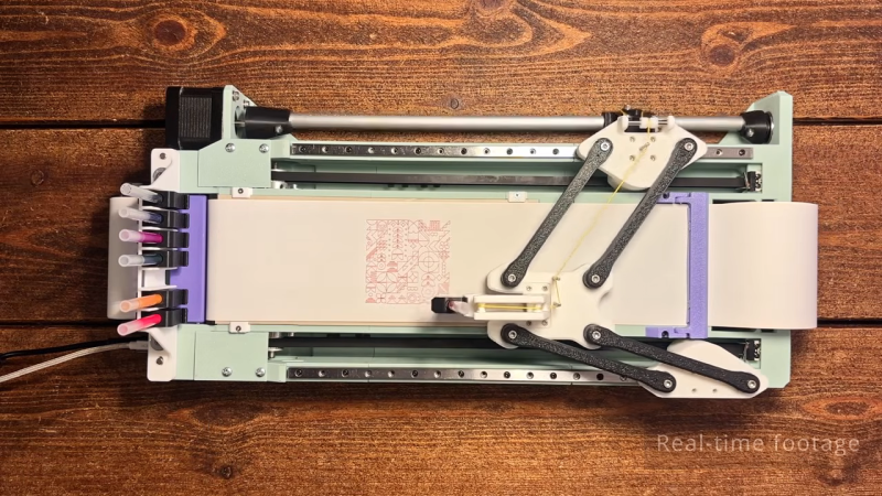
The build relies on a unique motion system, wherein two NEMA 17 stepper motors drive either side of the linkage to control the position of the end effector—in this case, a pen carriage. By controlling the position of each side of the mechanism, it’s possible to move the pen through XY space. Running the show is an Arduino Nano, fitted with a GRBL shield and appropriate stepper motor drivers.
The magnetic tool changer is particularly nifty, too. It allows the plotter to grab a different ink at will to add more color to the drawing. It’s well-designed, with the plotter able to change inks without losing accuracy or otherwise fumbling the switchover. The plotter uses Muji ball point pens, which are available in a range of colors and draw with slick, clean lines. It’s also quite a fast plotter, thanks in part to [András]’s efforts to keep the pen carriage light by using a smart mechanism to offload the pen lifting actuator to the main body.
[András] has plans available, but you’re going to have to pay for them. Still, it’s always nice to see a new machine in the wild. Video after the break.
The sport of fencing requires keeping score, just like so many other similar pastimes. When their club’s existing scoring rig broke, [jc0025] stepped up to build a scoring box of their own, using the typical tools of the maker trade.
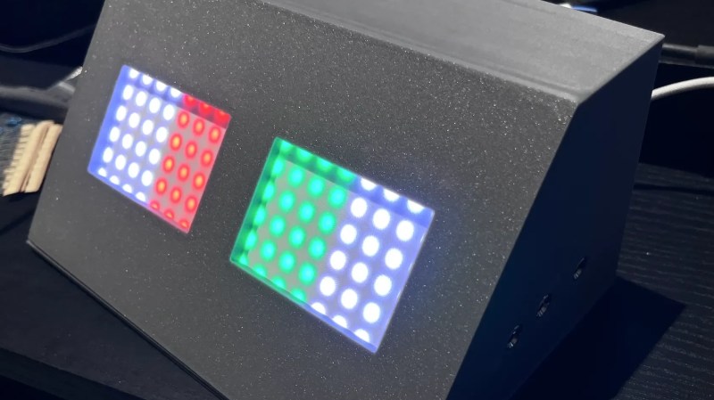
The brains of the operation is an Arduino Nano, running the venerable ATmega328P. It’s set up to drive a pair of 8×8 WS2812B addressable LED panels. It’s also hooked up to a pair of fencing socket blocks, which hook up to the lamé (jacket), weapon, and guard of each player for electronically scoring hits. The Arduino is thus programmed to respond to various conditions, lighting the LEDs in turn. For example, the tip of one player’s weapon hitting the other player’s lamé will fire a colored light, allowing the hit to be scored. Meanwhile, a tip hitting the floor will fire a white light, indicating off-target. There’s also a buzzer for sonic indication, as well. Everything is wrapped up in a tidy 3D-printed housing, while power is courtesy of a USB-C charger hooked up to the unit.
The Playdate is a small handheld console with a dedicated fanbase. Among them is [Cristina Ramos], who recently decided to try and push the limits of the hardware by implementing a 3D renderer for the platform.
[Cristina] began by implementing a raycaster. This is a very simple way to do 3D on limited hardware, and this technique was used by some early games like Wolfenstein 3D. However, for [Cristina], it was more a test to get an idea of the performance limitations of the Playdate. After getting her feet wet with that, she stepped up to implementing a renderer that relied on binary space partitioning, which could load map files in the same format used by the classic Quake engine. There was naturally plenty of work to do to handle things like texture mapping and lighting, too, particularly given the vagaries of working with the Playdate’s 1-bit monochrome screen. Using a simplistic, cel-shaded like approach for textures gave things a good look while preserving visual readability on the low-resolution screen.
The 3D engine and associated game remain a work in progress for [Cristina] — we look forward to seeing where the project goes next. We’ve seen similar projects on resource-limited platforms before, too.
I was told you couldn't do 3D on the Playdate, so I did it.Then I was told there was no way I could create exterior levels like those in Mirror's Edge, so I proved them wrong again.
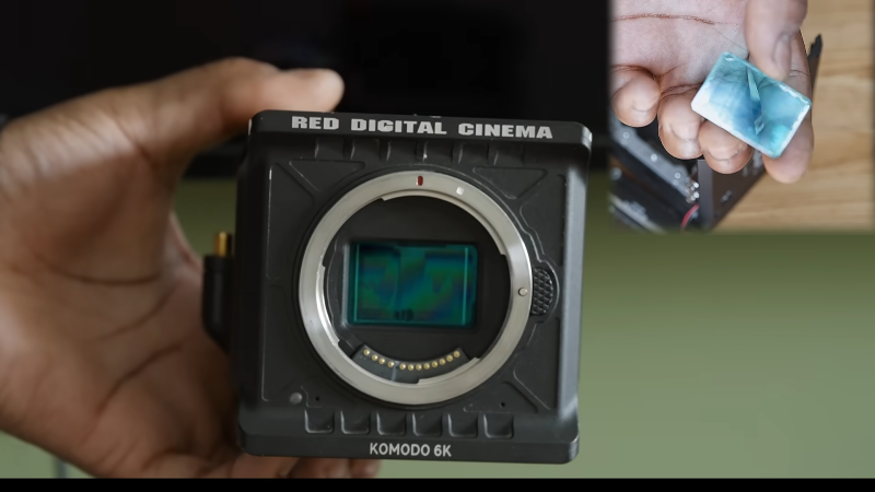
[ALT CINE] took a punt recently when purchasing a damaged RED Komodo camera online. In functional form, the 6K-capable camera sells for several thousand pounds (or dollars, or euros), whether used or brand new. However, [ALT CINE] was able to score the damaged unit for just £700. The question was—could it be repaired and turned back into a functional camera?
Things looked promising from the drop. The camera had just 3 hours of usage recorded in the firmware, and the casing seemed to suggest it had little use. However, the problem was soon revealed to be serious as the image sensor itself appeared to be damaged. Some research provided hope though—that the damage could be limited to a glass layer in front of the sensor itself that had delaminated.
Thankfully, disassembling the camera was easy enough thanks to its modular design, and [ALT CINE] soon had the sensor block on the bench for further examination. The cause of the issue was apparent—overzealous cleaning leading to fluid getting stuck to the rear of the filter in front of the sensor. Simply popping off the filter, cleaning and drying it properly, and reassembling, was enough to get the camera back to fully operational status.
RED’s repair service quoted $695 for a glass filter swap and $1,395 for a full sensor change. In contrast, [ALT CINE] was able to demonstrate that this repair was something easily within the realm of an intermediate camera tinkerer and it cost almost nothing to achieve. The video also covers an alternative potential repair route, wherein a DSMC2 filter can be subbed into a Komodo camera if the damage to the filter glass is otherwise unrecoverable.
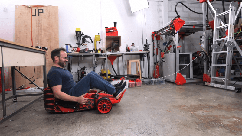
[Ivan Miranda] is famous for his large-scale 3D printed vehicles. They’re pretty fun, but they’re also pretty big and heavy—which can make transporting them around rather impractical. Hence, when he had reason to travel with a 3D printed go kart, he went back to the drawing board to create something light enough to pack in regular plane luggage.
The build started with some major compromises compared to [Ivan]’s previous go kart build. Notably, there are only three wheels instead of four, and a simplified control layout that eschews a regular steering wheel. These decisions were made to save weight and allow the design to be more compact. The kart uses a set of handles either side of the rider to handle steering. Drive is via a brushless motor, with power supplied from a series of 18 V drill batteries. Parts were produced on [Ivan]’s massive printer which comes in handy on large-scale projects like these.
All in all, the final build weighed around 20 kg. That’s light enough to be broken down across checked luggage and carry-on for a typical flight. We’d consider the project a success on that basis, even if quite a bit of assembly was required upon arriving at the destination. [Ivan]’s other builds in this realm are pretty fun too, from the printed scooter to the ride-on tank.
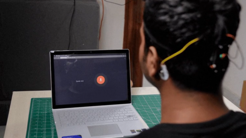
The standard computer mouse is a perfectly useful peripheral if your hands work. If you’ve got some trouble in that area, you might appreciate an alternative input solution. To that end, [Varun Adinath Patil] created a neat hands-free solution for moving a cursor around a screen.
The build is based on the Neuro PlayGround Lite, a board built for physiological signal acquisition in the Feather form factor. It’s hooked up to an IMU sensor—both a MPU6050 or BMI270 work—which tracks head movements to allow the cursor to be panned around the screen. Other biological signals are then used to activate other standard mouse functions. Clenching the jaw fires off a left click, while a triple blink fires a right click. Clicking and dragging is achieved by a double-blink. The jaw muscles are sensed via EMG signals picked up with gel electrodes on the skin, while the blinks are detected via EOG signals via the same contact points.
[Myth Made] has a goal to get into writing. However, she likes to do things the aesthetic way, rather than the easy way. Thus, she has eschewed simple word processing on a conventional computer, instead choosing to build a remarkably attractive writing deck styled after a classic typewriter.
The keycap marking technique is worth watching the video for on its own.
The build began with a mechanical keyboard with a compact layout. The square keycaps were swapped out for custom 3D printed versions that were rounded to suit the desired look. [Myth Made] used a neat technique where the caps were colored in with a paint marker and then ran through a laser engraver to bond the paint to the surface to make all the key markings.
With the input side sorted, the rest of the build could progress. The typewriter shell was printed in multiple parts, and then welded together with acetone. This was then covered with an ABS-acetone solution that helped remove some of the surface artifacts, before priming and paint. As for the electronics side, a Raspberry Pi Zero runs the show, hooked up to a Waveshare e-ink display which can be cranked up and down like a piece of paper coming out of a typewriter. There’s also a lovely 7-segment display which displays the current word count.
Even before 3D graphics and advanced shaders became common in the gaming world, there were concerns that virtual violence looked too realistic. Fighting games in the 1990s were routinely toned-down by having gratuitous displays of blood removed, which was often seen as disappointing by dedicated fans. [Raphaël Boichot] has been working to right this wrong in one obscure case, by rectifying the lack of blood in Sengoku 2.
Sengoku 2 was a title released in 1993 for the Neo Geo AES/MVS and the Neo Geo CD. It hit the market with relatively tame graphics that didn’t reflect the realistic amount of blood that should be released when an enemy was chopped in half with a sword. Noting that there was no simple DIP switch configuration or bit to flip to enable a more adult version of the game, [Raphaël] decided to create a custom blood hack the hard way. What ensued was a heavy-duty reverse engineering effort, swapping out palettes, and carefully editing tilesets in order to turn the censored graphics into something more lurid. A lot of artistic decisions had to be made to manipulate things just so in order to create a pleasing effect that didn’t mess up other aspects of the graphics at the same time.
If you’re a big Sengoku 2 fan, or you just want to learn more about reverse engineering and hacking on an obscure platform, dive into the project and enjoy the learnings. Otherwise, dive into the entirely different sorts of blood-related hacks we’ve featured over the years.
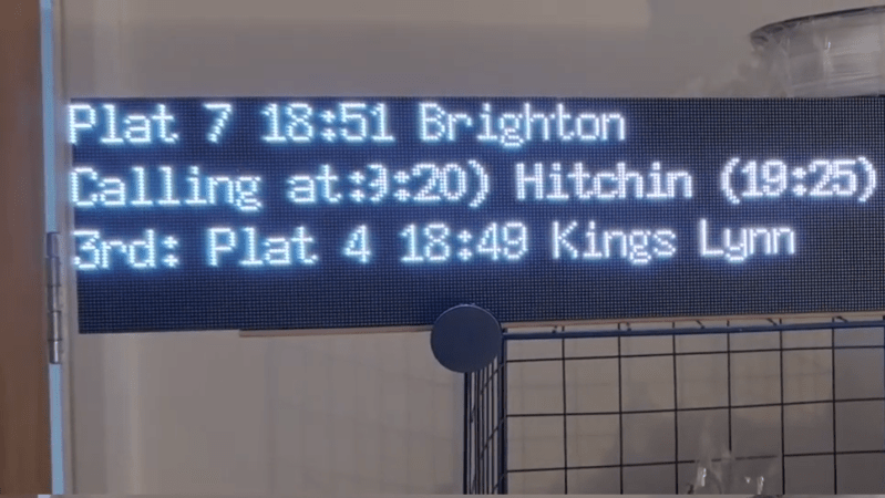
Trains are a great way to get around. You just have to make sure you’re across the schedule if you intend to get where you’re going in a timely manner. Train departure boards exist for that very purpose. As a train fan, [Jon] always wanted such a thing, so decided to build one for himself.
The build started, as so many do, with a Raspberry Pi 4, with [Jon] deciding on the 1GB model. Hooked up to either an Adafruit RGB Matrix Bonnet, or an Electrodragon 3-port RGB Matrix board, it’s then possible to get the Pi running three to four HUB75E LED matrixes. Each matrix consists of 128 x 64 pixels, so stacking up a bunch of them can make a nicely-sized departure board that’s easily readable. [Jon] was sure to hook up a nice, juicy 5-amp 5-volt power supply to ensure there wouldn’t be any surprise brownouts under normal usage conditions. From there, it’s simply a matter of having the Pi query the Rail Data Marketplace in order to get the relevant schedule data to display on the board.
If you want to get information on your local rail services at a glance, or just want to impress your fellow foamers at your next railfan gathering, a build like this is a great way to go. We’ve seen similar builds before, too. Video after the break.
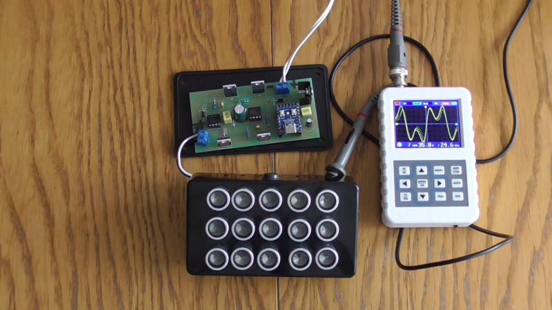
Today’s phone microphones are perfectly adept at picking up sound in all sorts of conditions, and they’re backed by all kinds of processing techniques to filter out noise and capture clean audio. [mcore1976] has been working on a device to jam phone microphones that might be listening in, however, countering fancy processing techniques in turn.
The build uses a microcontroller brain to control an array of ultrasonic transducers. [mcore1976] has created many revisions of the project, each time improving its ability to jam microphones in modern hardware. The latest revision uses an RP2040 microcontroller and a MOSFET drive stage to control 20-80 ultrasonic transducers. They’re driven with a PWM signal generated from the RP2040 itself. The signal output is specifically modulated to try and confuse the automatic gain control systems used in many modern phones in order to make it difficult for them to record clear audio when the jammer is running. As [mcore1976] demonstrates with an iPhone 17, his voice is completely lost amidst unintelligible garbled noise while the jammer is switched on.
A great many drones out there, whether homebuilt or store-bought, follow the same basic format. Four motors, some kind of controller, and a lithium-polymer battery supplying the juice to keep everything in the air. It’s a format that produces a remarkably capable air vehicle, suitable for everything from high-speed camera work to urban search and rescue.
With that said, the format does have its limitations. [Suryansh Sharma] has been working on alternative designs for fancy and interesting drones that are half quadcopter and half blimp, and he came to Hackaday Europe 2026 to tell us all about it.
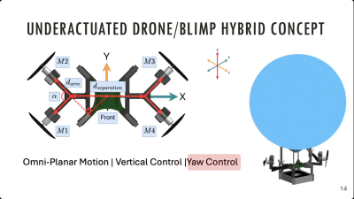
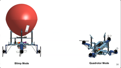
Combining a multirotor design with a balloon for additional lift proved useful for certain applications. Despite the motors all being mounted in the horizontal plane, vertical translation is possible by firing the right combination of motors, due to convenient aerodynamic effects. Credit: slides
[Suryansh]’s talk took in a number of drone projects which he has been involved with. The first was the creatively-named BEAVIS, or Balloon Enabled Aerial Vehicle for IoT and Sensing. This was a project that aimed to tackle one of the greatest limitations of the common multirotor drone. Namely, as [Suryansh] so elegantly puts it, they “suck when it comes to staying in the air.” This is for a very simple reason—much like the helicopter, a multirotor drone must expend energy continuously to generate lift by spinning its propellers. Conventional multirotors don’t have wings that generate lift from forward motion, and any sort of gliding or similar behavior is basically impossible. Continual energy expenditure is the only thing keeping a multirotor aloft.
The point of BEAVIS was to fix this by combining drone tech with a simple lighter-than-air balloon. It’s an interesting combination, because a multirotor drone has excellent maneuverability and agility, but terrible endurance. A lighter-than-air balloon is quite the opposite, which has excellent endurance while suffering in all other respects. The BEAVIS concept outfits a small balloon with four motors in a split-cross configuration, which allows for planar translation as well as the ability to control yaw of the craft. With all four motors mounted horizontally in the same plane, it may seem like vertical control is not possible. However, by turning on two opposing props, it’s possible to create a low-pressure region beneath the craft which tends to push it downwards. Meanwhile, if you turn all four props on in the right directions, you create a high pressure region underneath the balloon which pushes the craft up. With the balloon, it has the benefit of being able to just hang in the air without continually burning through battery power. Endurance times of well over an hour were possible with this build, compared to maybe less than ten minutes for a comparable pure multirotor.
BEAVIS was developed into JANUS, a drone with an actuator system that pivots the motors so that it can fly in a pure quadcopter mode in the event of balloon failure. Credit: slides
BEAVIS was eventually developed into Janus— described as a “morphing quadrotor blimp with balloon failure resilience.” The goal was to build a craft that was viable for deployment in the real world, and that could undertake mobile ecological sensing work. The main difference to the previous design was that it would no longer solely fly as a balloon with horizontally-mounted props. Instead, Janus would feature a mechanism to allow the rotors to be positioned in the vertical axis to allow for conventional multirotor flight. This was key to allowing the craft to fly both as a lighter-than-air craft, and to survive and keep flying in the event the balloon burst or was otherwise damaged. The build was eventually deployed in Kenya to aid in ecological data collection for conservation efforts.
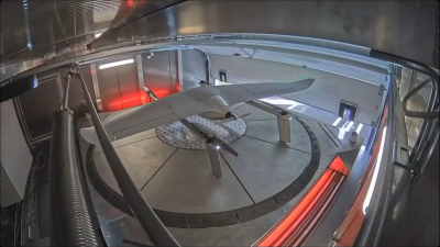
The Avy emergency response drone uses a metal launchpad and pogo pins to provide electrical power to keep the batteries topped off at all times. Credit: slides
[Suryansh] has been involved in other drone-related projects, too. Open Gimbal was a particularly interesting effort, involving the construction of a bench-testing rig for developing small multirotor drone craft. The 3-DoF platform offered unrestricted rotational freedom, allowing for a craft to be put through its paces in a controlled way without requiring a large open space for free flight. [Suryansh] also discusses his work with a company called Avy, which specializes in VTOL drones with a focus on emergency response roles. The company has deployed drones that use multirotor technology to launch vertically, while relying on fixed wing aerodynamic elements to extend range and improve efficiency for longer flight times. The drones feature a neat charging setup, wherein pogo pins on the fins pick up power from the metal launchpad to ensure that batteries are fully charged and the drone is ready to go at all times.
Ultimately, multirotor drones have taken on their basic form for good reason. With that said, as [Suryansh]’s talk explains, modifications to the form can have great utility when made to suit a particularly specific mission or application. If you’re developing a drone for a certain purpose, and you’re running into hard limitations, you might try thinking outside the box to make something more fitting for your goals.
Running DOOM on weird obscure hardware is a fun hacker pastime that’s been around for a long time now. It’s always enjoyable to see someone port it to an egg timer, or a hat, or whatever else. But what about running the iconic shooteron a CPU of your very own? [Armaan] and [Liam] have done just that.
The CPU in question was designed at the logic gate level, deployed on to an FPGA, and hooked up with the necessary peripherals to run as a going concern. Early testing of the CPU involved running straightforward code to generate Mandelbrot sets and to play a simple game of Pong. But [Armaan] and [Liam] had bigger goals: to port the game that everybody ports to everything. Doing that took some work.
To get DOOM running, the CPU had to get faster, and it needed many tweaks to how memory was handled. There was also work to be done to create a keyboard interface, an HDMI video output, and a hardware timer. From there, the game itself had to then be ported to the custom CPU’s architecture. Eventually, the duo had the game running… at a glacial 0.7 FPS. A success, but not the magical end result that was desired. A bump to clock speed and further optimizations and compiler tweaks eventually got the game up to an impressive 15-20 FPS. The goal for future work is to push it to an entirely-playable figure of 30 FPS or better.
It’s worth checking out the (apparently unembeddable) videos on Instagram to see the CPU in action. We’ve also featured plenty of fun DOOM ports before, too. If you’re brewing up custom CPUs or DOOMports of your own, keep them coming to the tipsline. The latter in particular is often a wonderful milk run for the writer that happens across it. Happy hacking out there!
There was once a race to put out cameras with ever higher numbers of megapixels to snare customers eager to take the highest quality digital photos. These days, we know that things like optics, processing, and finer qualities of an image sensor are all very important beyond pure resolution. But, for a time, companies behaved as if megapixels mattered over all else.
But what if you could go farther—shooting not millions, but billions of pixels in a single image? That’s precisely what [Yannick Richter] came to Hackaday Europe to talk about, covering his Project Gigapixel build.
More Pixels
When it comes to building a consumer camera with higher resolution, manufacturers achieve this by creating an image sensor with a greater number of sensing elements. This, of course, can get expensive and difficult the farther you want to scale, particularly if you’re trying to fit more sensing elements into a given standard sensor size.
A scanner sensor has great linear resolution. Pan one behind a high-quality lens, and you can capture images in super high resolution… just hope that nothing moves while you’re capturing a shot!
However, there are other ways to capture images in greater resolution that don’t require a larger image sensor. Namely, you can actually use quite a simple image sensor of limited resolution, and simply move it to various positions, capturing light all the while. Then, all you need to do is stitch the output together and you have a remarkably high resolution image. It might sound complicated, but as [Yannick] explains, it’s a perfectly cromulent way to build a gigapixel image.
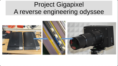
[Yannick’s] project began with an old Epson flatbed scanner. This made the perfect donor for such a project, as it came with a linear image sensor with quite good resolution for scanning photographs and documents. The only problem is that it needs to move in a straight path in order to capture a full image. The goal was to build it into a scanner-style camera that was truly portable, which required some reverse engineering and creative design to make it into a practical tool for real-world photography. [Yannick] didn’t want to just stuff the existing scanner in a bodged-together camera body, either. He wanted to interface the sensor directly and build a custom linear-scanning camera from the ground up, with the high-resolution linear sensor mounted behind a nice medium-format Pentax lens.
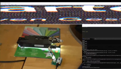
[Yannick] lashed up a Raspberry Pi to read from the sensor.The key was that the scanner in question—an Epson V370—used a Sony CCD scanning element, rather than a cheaper CIS element. A proper CCD sensor is more expensive, but produces better output, and is more suitable for the sort of imaging [Yannick] was trying to do with this build. Namely, by running the scanning element behind a medium format lens to capture incredibly high-resolution images at up to 40800 x 80000 pixels, or 3.2 gigapixels if you multiply it out.
The talk covers all the work that [Yannick] did to make this a fully functional camera. That included doing a deep dive into Epson documentation to figure out how to interface the sensor at all. Thankfully, service manuals provided enough detail on how the 12-line RGB sensor works to get the project over the line. Interfacing the sensor was achieved via reusing the ADC and timing generation hardware from the scanner itself, hooked up to a Raspberry Pi 5 and a RP2350.
Plenty of work was required to figure out how to properly offset all the R, G, and B pixels to line up properly into a coherent color image. [Yannick] also dives into the mechanical design, regarding how the sensor was assembled on a 100-millimeter linear drive to scan it behind the lens assembly to capture images. There were also issues generating a live preview that you’d get on any other digital camera, which is not exactly practical to generate from a scanning image sensor. Instead, a standard Raspberry Pi camera was included in the build for live preview to help with lining up a shot.
The camera is capable of taking incredibly high resolution images with rich detail. Of course, image sizes are hefty in turn.
Perhaps the best part of the talk is when [Yannick] shows off the final results. The simple fact is that 3.2 gigapixel images capture a ton of detail when they’re taken well and focused correctly. A simple shot of some benchtop instruments doesn’t look like anything special, until [Yannick] shows that cropping in will let you read the codes off a 0603 SMD resistor. Obviously, the camera is limited when it comes to speed and it can’t really capture moving objects well. However, when it comes to grabbing very high resolution shots of still scenes, it’s a great performer. If taking gorgeously detailed landscapes or stunning architectural shots is your thing, you might find such a build an appealing proposition for your own needs.
Even for those of us that are quite technically minded, we spend precious little time thinking about the cables that carry our signals and do all the important work we need them to do on a daily basis. A great deal of theory and engineering goes into making things like telephone lines and HDMI cables work, but we mostly just plug them in and get on with whatever we’re doing.
If this is your experience, you might find the Hackaday Europe talk from [Michael Wiebusch] to be particularly interesting. He dives into transmission line theory from an accessible standpoint, explaining how two disparate signals can go in opposite directions on the very same wire. Then he demonstrates the theory by building a cable modem… well, sort of!
Signal
Michael begins his talk by discussing the Telegrapher’s Equation, but only as a fakeout. Given the limited time on offer, he decided a quicker, easier explanation of the physics involved would be more appropriate. Key to this was explaining the difference between cables and transmission lines. To create a true transmission line, by his definition, he explains that there is a necessity to have two conductors that are relatively close together. Such a transmission line is effectively a distributed network of inductances and capacitances all the way down, though often we talk about “lossless” transmission lines for modelling purposes. He also covers the point of coaxial cables, wherein one conductor is wrapped around another to shield a signal from external noise, and to prevent signal from leaking out.
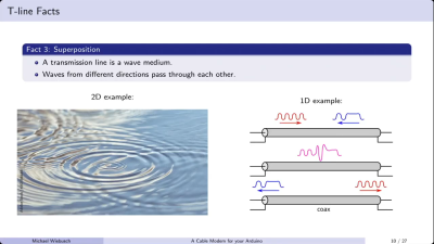
Transmission lines allow signals to pass in opposing directions, much like ripples on a pond will pass through each other, retaining their form. Credit: talk slides
There are several basic facts to remember about transmission lines. They are fundamentally just channels down which EM signals can travel. It’s also good to remember that they delay signals. To a human, the signal may appear to travel instantaneously, but it does take time. This also has other impacts; for example, coax cables are filled with plastic, a material in which the speed of light is roughly 66% of the speed of light in a vacuum.
This slows the rate at which the field of an EM signal can travel to this fundamental limit. [Michael] also notes that transmission lines, as a wave medium, essentially allow waves travelling in different directions to pass each other, much like ripples spreading on the surface of a pond. This is why it’s possible to have bidirectional communication on a single transmission line. It’s also important to terminate a transmission line properly, such that the wave you’re transmitting down it ends where you want it to—at the receiver. Fail to terminate your transmission line, and you’ll have that wave bouncing back and forth which is undesirable for clear transmission.
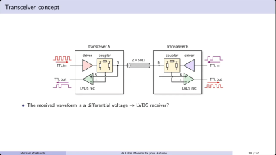
The coupler allows sending and receiving signals via a single transmission line. Credit: talk slides
[Michael] demonstrates basic transmission line theory by building a sort of cable modem out of an Arduino and some supporting hardware. He notes it’s not really a modem—there is no modulation or demodulation going on. Instead, he’s simply squirting TTL signals into either end of a cable and receiving them on the other end. The “black box” that couples the signals into and out of the transmission line is a simple directional coupler. Built out of resistors and an op-amp, it allows sending a signal down a transmission line, as well as receiving a signal coming the other way. The design works all the way down to DC logic level signals, which let [Michael] use it to send TTL signals up and down 50-ohm and 75-ohm coaxial cables. He notes this has very obvious practical applications where it’s desirable to reduce cable counts when sending signals in multiple directions, relating this directly to his professional work on science experiments.
If you’ve ever wanted to get two devices talking over a single cable in a relatively easy fashion, then [Michael’s] talk may be valuable to you. At the very least, it’s a great way to learn some of the basics of transmission lines and better understand what’s going on when you shoot a signal down a random bit of wire. It’s all good stuff.

 Login
Login